Carrier 60 User manual

Models 60 & 62
Shake Freezers
Service Manual
051059-S 8/98


Models 60 & 62 Table of Contents
Table of Contents
Section 1: Introduction 1...............................................
Safety 2.............................................................
Refrigerant 2.........................................................
Model 60 Specifications 3..............................................
Model 62 Specifications 4..............................................
Running Specifications 5...............................................
Installation Instructions 6...............................................
Section 2: Controls 7...................................................
The Taylor Torque Control 8............................................
Auto-Lift System 9....................................................
Air/Syrup Delivery System 11............................................
Section 3: Troubleshooting 15...........................................
General Troubleshooting Guide 16.......................................
Electrical Troubleshooting 19............................................
Section 4: Parts 21......................................................
Warranty Explanation 22................................................
Model 60 Operator Parts 23.............................................
Model 62 Operator Parts 24.............................................
Model 60 Exploded View 25.............................................
Model 60 Control Assembly (X48805--27A) 230--60--1 28...................

Table of Contents Models 60 & 62
Table of Contents -- Page 2
Model 60 -- Compressor A.-Air (X47283--27G) 30..........................
Model 60 Valve A.-Solenoid (X48910--27) 31..............................
Model 60 Manifold A.--Regulator (X47285) 32.............................
Model 60 Motor A.-Lift (X48897--27) 33...................................
Models 60/62 Torque Switch A. (X29869-SER) 34..........................
Models 60/62 Draw Switch Assembly (X48896) 35.........................
Model 62 Box A.-Cap & Relay (X49934-27) 230-60-1 36....................
Models 60/62 Beater Assembly 37.......................................
Models 60/62 Syrup Tank 38............................................
Model 62 Control Assembly (X49995--27A) 230--60--1 39...................
Model 62 -- Valve Assembly--Solenoid (X49930--27) 41.....................
Model 62 Regulator A.-Remote (X23969) 42..............................
Parts List 43...........................................................
Wiring Diagrams 55....................................................
E
A
ugust, 1998 Taylor
All rights reserved.
051059--S
The word Taylor and the Crown design
are registered trademarks in the United States
of America and certain other countries.
Taylor
a division of Carrier Commercial Refrigeration, Inc.
750 N. Blackhawk Blvd.
Rockton, IL 61072

1
Models 60 & 62 Introduction
Section 1: Introduction
SSpecifications
SRunning Specifications
SInstallation Instructions

2
Introduction Models 60 & 62
070309
Safety
_________________________________
We at Taylor are committed to manufacturing safe
operating and serviceable equipment. The many
built-in safety features that are part of all Taylor
equipment are aimed at protecting operators and
trained service technicians alike.
This manual is intended exclusively for Taylor
authorized service personnel.
DO NOT operate the freezer unless it is
properly grounded.
Stationary appliances which are not equipped
with a power cord and a plug or other device to
disconnect the appliance from the power source must
have an all--pole disconnecting device with a contact
gap of at least 3 mm installed in the external
installation. Failure to follow this instruction may result
in electrocution.
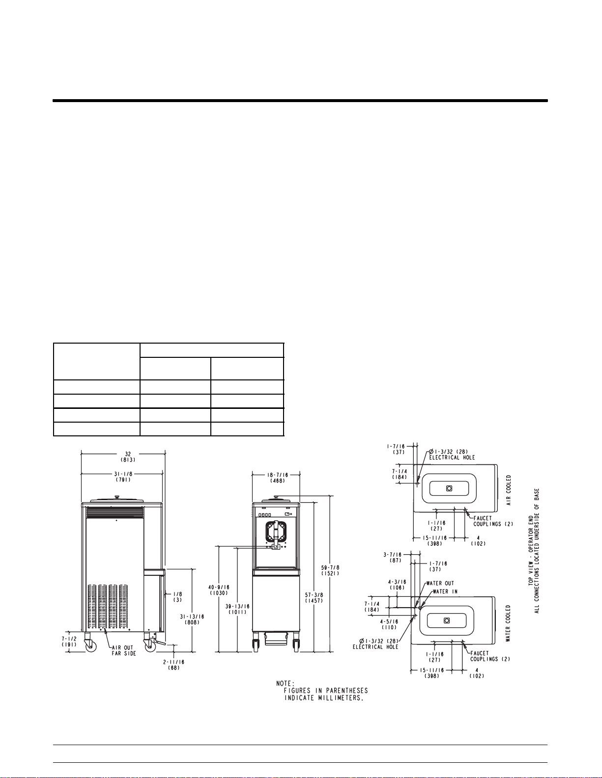
These machines must be placed on a level
surface. Failure to comply may result in personal injury
or equipment damage.
DO NOT install the unit in an area where a
water jet could be used to clean or rinse the freezer.
Failure to follow this instruction may result in serious
electrical shock.
These machines are designed to operate indoors,
under normal ambient temperatures of 70_-- 7 5 _F
(21_-- 2 4 _C). The machines have successfully
performed in high ambient temperatures of 104_F
(40_C) at reduced capacities.
NOISE LEVEL: Airborne noise emission does not
exceed 78 dB(A) when measured at a distance of 1.0
meter from the surface of the machine and at a height
of 1.6 meters from the floor.
Refrigerant
_________________________________
Taylor uses R404A refrigerant. This refrigerant is
generally considered non-toxic and non-flammable;
however, any gas under pressure is potentially
hazardous.
NEVER fill any refrigerant cylinder
completely with liquid. Filling the cylinder to
approximately 80% will allow for normal expansion.
Refrigerant liquid sprayed onto the skin may
cause serious damage to tissue. Keep eyes and skin
protected. If refrigerant burns should occur, flush
immediately with cold water. If burns are severe,
apply ice packs and contact a physician
immediately.
Taylor reminds technicians to be cautious of
government laws regarding refrigerant recovery,
recycling, and reclaiming systems. If you have any
questions regarding these laws, please contact the
factory Service Department.
WARNING: R404A refrigerant used in conjunction
with polyolester oils is extremely moisture
absorbent. When opening a refrigeration system, the
maximum time the system is open must not exceed
15 minutes. Cap all open tubing to prevent humid air
or water from being absorbed by the oil.
If the crossed out wheeled bin symbol is
affixed to this product, it signifies that this product is
compliant with the EU Directive as well as other similar
legislation in effect after August 13, 2005. Therefore,
it must be collected separately after its use is
completed, and cannot be disposed as unsorted
municipal waste.
The user is responsible for returning the product to the
appropriate collection facility, as specified by your local
code.

3
Models 60 & 62 Introduction
050512
Model 60 Specifications
Freezing cylinder
One, 7 quart (6.6 liter) capacity.
Mix Hopper
One, 20 quart (18.9 liter) capacity. Refrigerated and
insulated.
Beater Motor
One, 1.0 hp.
Refrigeration Unit
One, approximately 11,000 btu/hr compressor.
Refrigerant R404A.
One independent (SHR) compressor, approximately
400 btu/hr. Refrigerant R134a.
Electrical
One dedicated connection.
Electrical Maximum
Fuse Size
Minimum
Circuit Ampacity
208-230/60/1 Air 25 21
208-230/60/1 Water 25 20
208-230/60/3 Air 20 17
208-230/60/3 Water 20 17
This unit is manufactured in other electrical
characteristics. Refer to the Distributor Data Book for
availability. (For exact electrical information, always
refer to the data label of the unit.)
Air Cooled
Clearance: 3” (76 mm) around all sides.
Water Cooled
Water inlet under side of base 3/8” FPT.
Dimensions
Width: 18-7/16” (468 mm)
Depth: 32” (813 mm)
Height: 59-7/8” (1,521 mm)
Floor Clearance: 7-1/2” (191 mm) mounted on
standard casters.
Approximate Weights
Net: 520 lbs. (235.9 kgs.)
Crated: 580 lbs. (263.1 kgs.), 35.4 cu. ft. (1.0 cu. m.)
Specifications are subject to change without notice.
This unit is designed and constructed to meet stringent
safety and sanitation requirements for NSF and UL.

4
Introduction Models 60 & 62
061201
Model 62 Specifications
Freezing cylinder
One, 7 quart (6.6 liter) capacity.
Mix Hopper
One, 20 quart (18.9 liter) capacity.
Refrigerated and insulated.
Beater Motor
One, 1.0 hp.
Refrigeration Unit
One, approximately 11,000 btu/hr compressor.
Refrigerant R404A.
One independent (SHR) compressor, approximately
400 btu/hr. Refrigerant R134a.
Electrical
One dedicated connection.
Electrical Maximum
Fuse Size
Minimum
Circuit Ampacity
208-230/60/1 Air 20 17
208-230/60/1 Water 20 16
208-230/60/3 Air 20 15
208-230/60/3 Water 20 14
This unit is manufactured in other electrical
characteristics. Refer to the Distributor Data Book for
availability. (For exact electrical information, always
refer to the data label of the unit.)
Air Cooled
Clearance: 6” (152 mm) on both sides. It is
recommended to place the rear of the unit against the
wall to prevent recirculation of warm air.
Water Cooled
Water inlet under side of base 3/8” FPT.
Dimensions
Width: 22-7/16” (575 mm)
Depth: 31-3/16” (792 mm)
Height: 32” (813 mm)
Counter Clearance: 4” (102 mm) mounted on standard
legs.
Approximate Weights
Net: 346 lbs. (157.0 kgs.)
Crated: 378 lbs. (171.5 kgs.), 20 cu. ft. (.56 cu. m.)
Specifications are subject to change without notice.
This unit is designed and constructed to meet stringent
safety and sanitation requirements for NSF and UL.
6-1/2
(165)
1-3/4 DIA
(44) HOLE
FOR SYRUP
LINES
5-1/16
(129)
2
(51)
31-1/4
(794)
1-3/16 DIA.
(30) HOLE FOR
ELECTRICAL
CONNECTION
3/4
(19)
1-1/2
(38)
19-1/4
(489)
3-7/16
(87)
5-15/16
(151)
22-7/16
(570)
OVERALL
WIDTH
TOP VIEW - BASE PAN
OPERATOR END
NOTES:
1. FIGURES IN PARENTHESES INDICATE MILLIMETERS.
2. *NOTES FOR WATER COOLED UNITS ONLY.
22 (559)
C.L. OF LEGS
LEFT SIDE VIEW
1-1/4
(32)
4-1/4
(108)
12-1/8
(308)
6
(152)
6-1/2
(165)
22-7/8
(581)
34-7/8
(886)
OVERALL
HEIGHT
13-3/8
(340)
C.L. OF
DRIP PAN
(FRONT)
20-3/4
(527)
C.L. OF
BARREL
3/8
(10)
3-1/4
(83)
OPTIONAL FAUCET
COUPLINGS (2)
*WATER OUT
*WATER IN
*WATER IN
(FOR RINSE)
20
(508)
MIX HOPPER
30
(762)
34-7/8
(886)
OVERALL LENGTH
AIR IN
(THIS SIDE)
AIR OUT
(FAR SIDE)
5-5/8
(143)
14
(356)
5-1/2
(140)

5
Models 60 & 62 Introduction
Running Specifications
Expansion Valve (AXV) Setting
31-33 (213.7 - 227.54 kPa) for most products.
Low Side Pressure
Low side pressure = expansion valve setting.
To adjust the low side pressure, place the gauge on the
low side suction port at the compressor. With the
compressor running, turn the adjustment knob of the
automatic expansion valve clockwise to raise low side
pressure and counterclockwise to lower pressure.
High Side Pressure
Air Cooled: The following chart indicates normal
operating head pressures at various ambient
temperatures:
Ambient Temperature
Normal
Operating Head
Pressures
F. C. PSI
70_21.1_270-300
(1,862 - 2,069 kPa)
80_26.7_300-330
(2,069 - 2,275 kPa)
90_32.2_330-360
(2,275 - 2,482 kPa)
100_37.8_360-400
(2,482 - 2,758 kPa)
Water Cooled: Recommended head pressure is 255
PSI (1,758 kPa).
E.P.R. Valve Setting
The product temperature in the mix hopper is
maintained by the main refrigeration system and can
be adjusted by the E.P.R. valve. The E.P.R. valve is
factory set at 20 - 22 PSI (137.9 - 151.7 kPa) in order
to maintain hopper product temperature at
approximately 40_F. ( 4 _C.). To adjust the hopper
temperature, place the gauge on the access port at the
inlet of the E.P.R. valve. With the compressor running,
loosen the locking nut and turn the adjustment screw
(located on the top of the valve) clockwise to raise the
pressure for higher hopper temperatures and
counterclockwise to decrease the pressure for lower
temperatures. When the adjustment is complete,
tighten the locking nut.

6
Introduction Models 60 & 62
Installation Instructions
Air Cooled Units
Air cooled units require a minimum of 6” (152 mm) of
clearance around all sides of the freezer. Failure to
allow for adequate clearance can reduce the
refrigeration capacity of the freezer and possibly
cause damage to the compressor.
Water Cooled Units
A cold water supply must be provided with a hand
shut-off valve. Refer to the “Specifications” section in
this manual to identify inlet and outlet water
connections for the condensers. 3/8” FPT water
connections have been provided. 1/2” water lines
should be connected to the unit. If there is more than
one unit, larger lines should be used. (Flexible lines are
recommended if local codes permit.) The water lines
must be flushed of foreign substances before
connection. Depending on local water conditions, it
may be advisable to install a water strainer to prevent
foreign substances from clogging the water system.
After connecting the inlet water line, install a flexible
drain line to an open trap drain. An open trap drain is
used so that drain water flow can be observed. Do not
install a shut-off valve on the drain line. Incorrect
hook-up will result in continuous water flow through the
lines.
Recommended water pressure supplied to the unit is
35 PSI (241.3 kPa).
Electrical Connections
Each freezer requires one power supply. Check the
data label on the freezer for fuse, circuit ampacity and
electrical specifications. Refer to the wiring diagram,
provided inside the control box, for proper power
connections.
In the United States, this equipment is intended to be
installed in accordance with the National Electrical
Code (NEC), ANSI/NFPA 70--1987. The purpose of
the NEC code is the practical safeguarding of persons
and property from hazards arising from the use of
electricity. This code contains provisions considered
necessary for safety. Compliance therewith and
proper maintenance will result in an installation
essentially free from hazard!
In all other areas of the world, equipment should be
installed in accordance with the existing local codes.
Please contact your local authorities.
Stationary appliances which are not equipped with a
power cord and a plug or other device to disconnect
the appliance from the power source must have an
all--pole disconnecting device with a contact gap of at
least 3 mm installed in the external installation.
FOLLOW YOUR LOCAL ELECTRICAL CODES!
CAUTION: THIS EQUIPMENT MUST
BE PROPERLY GROUNDED! FAILURE TO
DO SO CAN RESULT IN SEVERE PERSONAL
INJURY FROM ELECTRICAL SHOCK!
Beater Rotation
Beater rotation must be clockwise as viewed looking
into the freezing cylinder.
To correct rotation on a single-phase unit, exchange
leads inside the beater motor. (Follow the diagram
printedonthemotor.)
CAUTION: Make sure the power switch is
in the OFF position before correcting the beater
rotation. Failure to do so may result in
electrocution or component damage.
Electrical connections are made directly to the
terminal block provided in the control box.

7
Models 60 & 62 Controls
Section 2: Controls
STaylor Torque Control
SAuto Lift System
SAir/Syrup Delivery System

8
Controls Models 60 & 62
The Taylor Torque Control
Function and Operation
The thickness of the shake product is controlled by a
sensing device called the torque switch. The
refrigeration system is de-activated by a micro switch.
The refrigeration system is activated by a timer.
Thickness of the product in the freezing cylinder is
measured by the torque rotor. The torque rotor is
installed through the center of the beater assembly.
When the beater assembly turns, the moving product
freezes and thickens. As the product thickens, it exerts
pressure on the torque rotor. This pressure causes the
torque arm at the end of the rotor to move to the right.
As the torque arm moves, it forces the operating lever
against a spring which trips a micro switch. This switch
de-activates the coil of a time delay relay. In turn, the
time delay relay stops the compressor, and
refrigeration ceases. When the OFF cycle has
elapsed, the compressor and the beater motor are
activated.
The beater motor must be running to monitor the
thickness of the product and to determine whether
refrigeration is needed. When drawing product, the
beater motor is running and the product thickness is
being monitored. If no product is drawn for long periods
of time, the beater motor will run every 4 minutes for
approximately 9 seconds to verify product viscosity. If
refrigeration is required, the compressor will start. If
not, the beater will stop after the 9 seconds.
Each time the draw handle is raised, the micro switch
is tripped and the beater motor will start.
Adjusting the Torque Switch
To serve a thicker shake product turn the adjustment
knob clockwise. This will increase the spring tension,
making it more difficult for the torque arm to move the
operating lever which trips the micro switch.
For a thinner shake product, turn the adjustment knob
counterclockwise.
Figure 1.

9
Models 60 & 62 Controls
Auto-Lift System
Function
The auto-lift mechanism consists of a motor, a cam,
and two micro switches. The cam lifts the draw arm,
and the switches control rotation of the cam. One
switch stops the draw arm when it is in the raised
position. The other switch stops the draw arm when it
is lowered. These two switches are controlled by the
foot pedal switch.
Figure 2.
When the foot switch is pressed, the coil of the lift relay
is energized and the switch points start the lift motor.
The motor runs until the return switch roller drops into
the cam notch. Once this occurs, the motor
discontinues with the draw arm in the raised position.
When the foot switch is released, the lift relay returns
to its rest position. The motor runs until the front or lift
switch roller drops into the cam notch.
Note: The auto-lift will operate in the AUTO or WASH
positions.
Lift Motor
A disc type brake is mounted to the lift motor armature.
This brake keeps the motor from “free-wheeling” after
the power supply is disconnected, and allows the cam
to stop at the correct position. When either of the cam
switches stop the power supply to the lift motor, a
spring moves the armature backward to engage the
disc brake. When power is supplied to the motor, the
torque moves the armature forward which overcomes
the spring tension and separates the discs. The motor
also is protected thermally with an automatic reset.
Figure 3.
Auto-Lift Relay
The auto-lift relay (encased in a clear, plastic housing)
is located in the upper control panel and is mounted
into a plug type socket base. The wires are connected
to the socket base.
The auto-lift relay is an ordinary double pole, double
throw relay. It controls the auto-lift system. The relay
coil is energized by the foot switch. When the foot
pedal is pressed, the relay energizes and supplies
power to the auto-lift motor assembly. When the foot
pedal is released, the relay de-energizes.
If the relay does not operate, the auto-lift system will
not work. If the relay sticks in the energized position,
the draw arm will be held in the raised position. If this
occurs, place the control switch in the OFF position.
This will discontinue beater operation and syrup
delivery.

10
Controls Models 60 & 62
Draw Switch Assembly
The switch assembly consists of three switches:
Sthe left hand switch which operates the
syrup solenoid valves
Sthe center switch which operates the spinner
motor
Sthe right hand switch which operates the
beater motor
All three switches are controlled by draw arm
movement. The left switch activates when the draw
arm is raised 1/2 to 5/8 of an inch (1.3 to 1.6 cm.). The
center and right switches are activated when the draw
armisraised1/4to3/8ofaninch(.64to.95cm.).
Figure 4.
All 3 draw switches are adjustable.
If the left switch is out of adjustment, the following
symptoms will occur:
SToo much syrup will be present at the top
and at the bottom of the shake. The syrup
solenoid is opening too soon and closing too
late.
SToo little syrup will be present at the top and
at the bottom of the shake. The syrup
solenoid is opening too late and closing too
soon.
If the center switch is out of adjustment, the following
symptoms will occur:
SThe spinner motor will run continuously after
the draw valve is lowered.
SProduct will be dispensed from the spinner
housing before the spinner starts.
Note: The spinner motor will continue to operate 5
seconds after the draw arm is lowered. This is due to
the 5 second time delay relay.
If the right switch is out of adjustment, the following
symptoms will occur:
SThe beater motor runs continuously.
SThe beater motor does not run until the draw
valveisraisedmorethan3/8ofaninch(.95
cm.).

11
Models 60 & 62 Controls
070131
Air/Syrup Delivery System
Syrup Component Functions
The spinner provides the automatic blending of any
one of three flavors into the neutral shake as it is
dispensed. Each flavor has a separate system which
requires regular cleaning and the correct type of syrup.
An air compressor supplies air pressure to the
pressure regulator.
The system for each flavor is composed of the
following components:
Spressure regulator
Spressure line assembly
Ssealed type stainless steel syrup tank
Ssyrup line (to solenoid valve)
Ssolenoid valve
Ssyrup line (from solenoid valve)
Sflavor selector switch
The pressure regulator controls the air pressure to
obtain the desired syrup flow. The air pressure is
produced by a single, central air compressor.
The pressure line assembly delivers the regulated air
pressure to the syrup tank.
The syrup tank provides syrup storage and may be
removed for cleaning by disconnecting the air and
syrup line quick disconnects.
The syrup line assembly delivers the metered syrup
to the solenoid valve.
The solenoid valve is an electrical valve and opens
only when the rocker switch is turned to either the
WASH or the AUTO position, the desired flavor button
is pressed, and the draw handle is raised. It will
continue to stay open until one of the following
switches have been moved.
SPress the vanilla flavor button (4th button
from the left).
STurn the rocker switch to the OFF position.
SLower the draw handle.
The second syrup line delivers syrup to the spinner
housing from the solenoid valve. Syrup is delivered
from this line only when the solenoid valve is
energized.
The flavor selector switch consists of 4 flavor
buttons. The left button is the No. 1 tank and lines. The
second button from the left is the No. 2 tank and lines.
The third button from the left is the No. 3 tank and lines.
The right selector button is in the OFF position and
may be used to dispense the unflavored product as a
vanilla shake.
Calibrating Syrup Flow
It is vital that the correct amount of syrup be
incorporated into the mix to obtain a quality shake.
Overly thin shakes are often caused by too much
syrup. Overly thick shakes are often caused by too
little syrup.
To determine the rate of syrup flow, use a calibrating
cup which indicates the ounces of liquid. Generally the
proper rate of syrup flow is 1 ounce (29.6 ml.) of syrup
in 6 seconds. Once this rate is set, the correct amount
of syrup will be blended with the shake base regardless
of the size of shake being served.
Press the vanilla button (far right button) on the
selector switch assembly. This button is used to stop
the syrup flow (OFF) and to draw a vanilla shake.
Rest the draw arm on top of the draw valve bracket.
Place the rocker switch in the WASH position.
Hold an empty cup under the spinner housing. Press
the first flavor button on the left and purge this syrup
line until pure syrup begins to flow steadily.
Note: It is very important to remove any sanitizing
solution or air from the syrup lines.
When the syrup is flowing steadily from the spinner
housing, press the far right button to stop the syrup
flow.
Position the large section of the calibrating cup under
the spinner housing.
With a timing device, press the first flavor button,
catching the syrup in the calibrating cup. When the
timing device reaches 6 seconds, press the far right
button to stop the syrup flow. If the amount of syrup
received is one ounce, the syrup is properly calibrated.

12
Controls Models 60 & 62
Adjusting the Syrup Pressure
If the amount of syrup received is less than 1 ounce
(29.6 ml.), the syrup pressure must be increased. If the
amount received is more than 1 ounce (29.6 ml.), the
pressure must be decreased.
Model 60
Inside the syrup compartment is an air pressure
manifold with individual regulators to control the
amount of pressure to each tank and syrup line. The
left regulator is used for syrup line number one and so
on.
Model 62
To make these pressure adjustments, use the
pressure regulators supplied with your freezer. The left
regulator is used for syrup line number one and so on.
Figure 5.
If less than 1 ounce (29.6 ml.) is received, the pressure
must be increased. Loosen the lock nut. Using a
flatblade screwdriver, turn the adjusting screw
CLOCKWISE.
Recheck the syrup calibration. Tighten the lock nut
after the correct calibration is achieved.
If more than 1 ounce (29.6 ml.) of syrup is received, the
pressure must be decreased. Loosen the lock nut and
turn the adjusting screw COUNTERCLOCKWISE to
zero. Remove the air line to the syrup tank to allow the
pressure in the tank to escape. Reconnect the air line.
Adjust the regulator to the new pressure setting and
recheck the syrup calibration. Tighten the lock nut.
Figure 6.
Figure 7.
Repeat the calibration procedures for each additional
syrup line.
Air System Components
Air Compressor: 230 volts, 60 cycle.
Check Valve: The check valve is a brass fitting which
is screwed into the discharge port of the air
compressor. When the compressor stops, the check
valve allows the pressure to be maintained in the air
storage assembly and the pressure at the discharge of
the compressor is allowed to dissipate.
Pressure Switch: The pressure switch is located next
to the air compressor. It automatically starts and stops
the compressor by measuring air pressure in the
primary line. This switch has been preset at the factory
to cycle on at 45 PSI and cycle off at 60 PSI.

13
Models 60 & 62 Controls
WE DO NOT RECOMMEND ADJUSTING THIS
SWITCH WITHOUT THE USE OF A PRESSURE
GAUGE.
Air Storage Assembly: The air storage assembly
stores and delivers from 45 - 60 PSI (310 - 414 kPa)
of air to the primary air regulator. It has the ability to
hold enough air to deliver 10 to 16 flavored shakes
before the air compressor must cycle on.
Primary Regulator: The primary regulator is used to
deliver 40 PSI (276 kPa) to the individual regulators.
For the model 62, the regulator has been locked into
position with a wire fastener. The model 60 has a
locking nut to secure the setting.
Individual Regulator: The individual regulators must
be adjusted to deliver enough pressure to achieve an
adequate syrup flow. Once the desired flow of syrup
has been achieved, the appropriate locking device
should be used to secure the regulator.
Individual Regulator Gauge: This gauge reflects the
Individual Regulator setting. The gauge should not
read more than 40 PSI (276 kPa). It will, however,
indicate a lower or no reading at all, when the following
situations occur:
1. Tank or tanks have been disconnected for
cleaning or refilling and then connected back to
the system. If the machine is on, this will be
momentary until the air compressor has
replaced the amount of air used to pressurize
the tanks.
2. The machine has been turned off for a period of
time, such as overnight.
3. There is a restriction in the primary air storage
line between the primary regulator and the
compressor.
4. There is an air leak in the primary air storage
line between the primary regulator and the
compressor.
5. There is an air or syrup leak somewhere in the
entire system.
Example: Sloose hose fittings
Spoor connection at the disconnects
Spoor seal at the syrup tank cover
Sholes in the braided tubing
6. There is a restriction at the suction port of the
air compressor.
7. The filters on the air compressor are dirty.
8. The air compressor is not operating properly.
9. The pressure switch is not operating properly.

14
Controls Models 60 & 62
Notes:

15
Models 60 & 62 Troubleshooting
Section 3: Troubleshooting
SGeneral Troubleshooting
SElectrical Troubleshooting

16
Troubleshooting Models 60 & 62
070131
General Troubleshooting Guide
PROBLEM PROBABLE CAUSE REMEDY
1. No product is being
dispensed.
a. There is inadequate mix in the mix
hopper.
a. Fill the mix hopper.
b. The control switch is in the OFF
position.
b. Place the control switch in the AUTO
position.
c. There is a freeze-up in the mix inlet
tube.
c. Adjust the mix hopper temperature.
d. The beater motor is out on reset. d. Reset the freezer.
e. Incorrect beater rotation. e. Correct beater rotation. See Installation
Instructions.
f. The beater motor will not activate with
the draw arm in the raised position.
f. Check wiring against the diagram.
g. Frozen clumps of product are
restricting the flow of mix to the freezing
cylinder.
g. Improper handling of rerun. Rerun must
be thawed completely and foam must
be skimmed off. Always mix 50% fresh
mix with 50% rerun.
h. The draw arm is not engaged in the
draw valve.
h. Center the draw valve on the draw arm.
2. Product is too stiff. a. Improper lubrication of the torque rotor
o-rings.
a. Lubricate the o-rings properly.
b. Improper consistency control
adjustment.
b. Product, with no syrup blended, should
be dispensed at 26 to 28_F (-3.3 to
-2.2_C). Adjust the control accordingly.
c. The torque rotor is binding. c. Before installing the torque arm, check
to see if the torque rotor can be rotated
freely without binding.
d. Not enough syrup is being blended with
product.
d. Calibrate the syrup system. Syrup
delivery should be 1 oz. (29.6 ml.) in 6
seconds.
e. The torque arm is not installed properly. e. Install the torque arm properly.
f. Faulty compressor relay. f. Replace the relay.
g. Faulty torque switch. g. Repair or replace the switch.
3. The product is too soft. a. Improper consistency control
adjustment.
a. Product, with no syrup blended, should
be dispensed at 26 to 28_F (-3.3 to
-2.2_C).
b. The torque rotor is binding. b. Before installing the torque arm, check
to see if the torque rotor can be rotated
freely without binding.
c. Improper lubrication of the torque rotor
o-rings.
c. Lubricate o-rings properly.
d. Lubrication of the torque rotor guide
bearing.
d. Do not lubricate the guide bearing.
Other manuals for 60
1
This manual suits for next models
1
Table of contents
Other Carrier Freezer manuals

Carrier
Carrier 50gs sizes 018-060 Installation manual

Carrier
Carrier 09VE Manual

Carrier
Carrier NEOS 100S User manual

Carrier
Carrier 50CD User manual

Carrier
Carrier C302 NPR User manual

Carrier
Carrier C708 User manual

Carrier
Carrier EC 2709N User manual

Carrier
Carrier Transicold 69NT40-561-199 Operation manual

Carrier
Carrier 2SF-13 User manual

Carrier
Carrier B5 Installation instructions