Carrier 2SF-13 User manual

SERVICE &
INSTALLATION
MANUAL
Chest
Freezers
51-1371-04
02/03
CARRIER COMMERCIAL REFRIGERATION, INC.
Providing BEVERAGE-AIR • FRIGIDAIRE • KELVINATOR • UNIVERSAL NOLIN Products/Services

If additional information is necessary, call the factory.
Our toll free number is 1-800-684-1199.Technical assis-
tance engineers are willing to assist you in any way pos-
sible. Office hours are from 7:30 a.m. to 5:30 p.m.,
Eastern Standard Time.
Important information is contained in this manual which should
be retained in a convenient location for future reference.
All data and information in this manual is subject to change without notice.
MODEL DESIGNATION INFORMATION
115V, 60HZ
PAR T NO. MODELS
52-1904-21 2SF-13
52-1904-22 4SF-13
52-1904-23 4DF-13
52-1904-24 6DF-13
52-1904-25 8DF-13
52-1904-33 8FR-13
52-1904-26 10DF-13
52-1904-27 14DF-13
52-2034-01 DI4-2
EXPORT 220V, 50HZ
PAR T NO. MODELS
52-1904-34 E2SF-13
52-1904-35 E4SF-13
52-1904-36 E4DF-13
52-1904-37 E6DF-13
52-1904-38 E8DF-13
52-1904-39 E8FR-13

SECTION I
General
Maintenance
&Repair
Ice Cream Cabinets
Except for routine cleaning, these chest freezers
require little maintenance. In the unusual event
that repair should be necessary, this manual pre-
sents information that is helpful in maintaining,
diagnosing, and repairing these cabinets.

Table of Contents
GENERAL MAINTENANCE & REPAIR
Installation/Operation .......................................................... 3
Grounding Instructions ...................................................... 4
Cleaning Instructions .......................................................... 5
Defrosting Instructions ...................................................... 6
2SF / 4DF / 4SF / DI4 Specs. & Drawings .......................... 7
6DF / 8DF / 10DF / 14DF Specs. & Drawings .................... 8
8FR Specs. & Drawings ...................................................... 9
General Operations Information ........................................ 10
Cabinet Construction ........................................................ 10
Cooling Tank Assembly .................................................... 10
Chamber Guards .............................................................. 10
Replacing Chamber Guards .............................................. 11
Lids .................................................................................. 11
Replacing Stainless Steel Top Cap .................................... 11
Refrigerating Systems ...................................................... 11
Condenser ........................................................................ 11
Filter Drier ........................................................................ 12
Capillary Tube .................................................................. 12
Heat Exchanger ................................................................ 12
Replacing Heat Exchanger ................................................ 12
Refrigerant Cycle - Condenser & Evaporator .................. 13
Electrical Service .............................................................. 14
Thermostat ...................................................................... 14
Condensate Heater ............................................................ 15
Motor & Relay .................................................................. 16
Checking For Electrical Trouble ........................................ 17
Refrigeration Service: Compressor Installation ................ 17
Refrigerant Service .......................................................... 17
Cleaning System After Burnout ........................................ 19
Wiring Diagram: Chest Models ........................................ 20
ELECTRICAL & REFRIGERATION
SPECIFICATIONS
2SF-13 & 4SF-13 (R-404A) .............................................. 21
4DF-13 & 6DF-13 (R-404A) .............................................. 22
8DF-13 / 8FR-13 & 10DF-13 (R-404A) ............................ 23
14DF-13 & DI4-1 (R-404A) .............................................. 24
PAR TS LISTS
Cabinet Parts Illustration (R-404A) .................................. 26
Cabinet Parts Listing (R-404A) ........................................ 27
Cabinet Parts Listing (R-404A) Export................................28
Condensing Unit Comp. Listing (R404A) Export ................29
Condensing Unit Compartment Illustration (R404A) ..........30
Condensing Unit Compartment Listing (R404A) ................31
Condensing Unit Compartment Illustration & Listing
Model DI4-1........................................................................32
8FR Parts Listing (R-404) & Accessory Mounting .......... 33
Cleaning Chocolate & Syrup Pumps ................................ 33
Accessory Mounting Limitations ...................................... 34
Caster Assembly Installation ............................................ 35
2TABLE OF CONTENTS

Installation & Operation Instructions
These instructions include information which is intended
to assure the operator of correct installation, operation,
and service. Before attempting installation, adjustment
or maintenance, be certain of the following:
1.That you have read and fully understand the instruc-
tions.
2.That you have all the tools required and are trained to
use them.
3.That you have met all installation and usage restric-
tions and are familiar with the functions and operation
of the unit.
4.That you follow all instructions exactly as given.
All fittings, measurements, procedures and recommen-
dations are significant. Substitutions and approximation
must be avoided. Improper handling, maintenance,
installation and adjustment or service attempted by any-
one other than a qualified technician, may void the
future warranty claims and cause damage to the unit
and/or result in injury to the operator and/or bystanders.
Record for Service
Model No. __________________________________
Serial No.____________________________________
Installation Date ______________________________
Invoice Date__________________________________
Start-up Date ________________________________
Telephone for Service __________________________
INSTALLATION INSTRUCTIONS
Thermostat will maintain approximately zero degrees on
the original factory setting. Turn the adjusting screw
clockwise for colder and counterclockwise for warmer.
IMPORTANT: Turning control counterclockwise to the
stop shuts cabinet "OFF".
For storage of package ice cream, turn thermostat to
coldest position. Limit top layer of package to a height
consistent with cabinet usage and turn over of product.
LOCATION
Select a location for the cabinet which will be most con-
venient for the customer and which will allow adequate
air circulation.Restricted air flow will result in higher con-
densing pressures and operating costs.
Provide at least a 1-inch space around the exterior of
the cabinet. The outside shell is the condenser and
depends on the natural convection of room air for dissi-
pation of its heat. Stainless or formica facing sheets
applied to the cabinet exterior should be in tight contact
with the cabinet's outer walls to improve the heat flow.
When a cabinet is built into a counter or back-bar and
space is allowed between the counter and the cabinet
walls, provide holes or louvers along the top edge for hot
air to escape.Holes should be screened to keep insects
and rodents out.
IMPORTANT: Before building any piece of equipment
in, run it to be sure the operation is satisfactory.
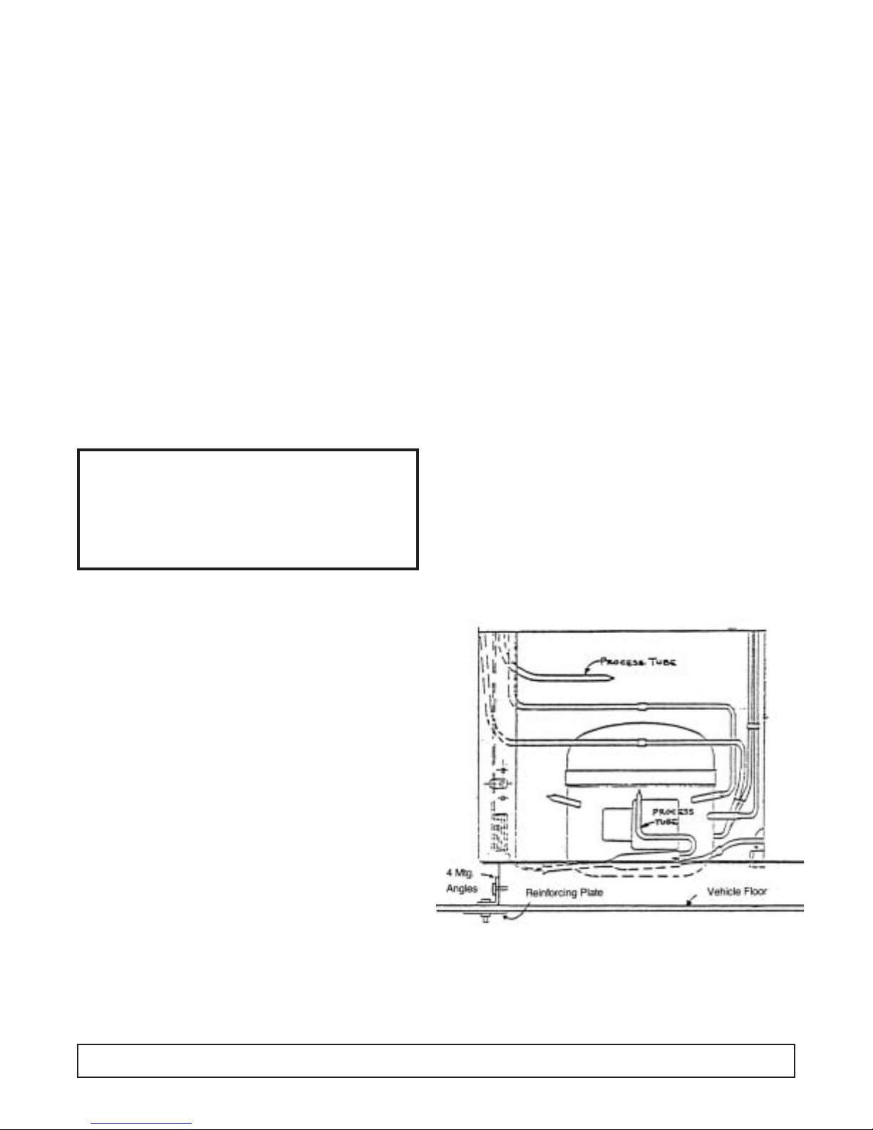
BE SAFE. SEE ILLUSTRATION ABOVE.
When a cabinet is installed in a moving vehicle, use the
original crate mounting angles or equivalent to securely
bolt the cabinet to the vehicle floor so it won't move
going around corners or during sudden starts and stops.
INSTALLATION & OPERATION 3
Important information is contained in
these instructions which should be
retained in a convenient location for
future reference.

Grounding Instructions
This appliance is equipped with a three-prong (ground-
ing) plug for your protection against shock hazards.The
appliance should be plugged directly into a properly
grounded three-prong receptacle.
Where a two-prong wall receptacle is encountered, it
must be replaced with a properly grounded three-prong
receptacle in accordance with the National Electrical
Code and local codes and ordinances. The work must
be done by a licensed electrician.
IMPORTANT
Do not, under any circumstances cut or remove the
round grounding prong from the appliance plug.
WARNING
Consult a licensed electrician if you have any
doubt about the grounding of your wall
receptacle. Only a licensed electrician can
determine the polarization of your wall
receptacle. Only a properly installed three-
prong wall receptacle assures the proper
polarization with the appliance plug.
4GROUNDING INSTRUCTIONS
20 Amp
15 Amp
15 Amp
20 Amp

FIG. 2
Cleaning Instructions
DIRECTIONS FOR PROPER CARE &
CLEANING
1.Wipe up spilled foods promptly.
2. Use lukewarm detergent solution for cleaning the
cabinet interior, exterior, and lids.Follow with a clean,
damp cloth and then wipe dry.
3. Protect the exterior enamel finish and plastic lid frame
with automotive type cleaner and wax.
4. Protect all stainless steel surfaces with a commercial
silicone emulsion type cleaner. This cleaner is excell-
ent for all stainless steel surfaces. It leaves a protect-
ing film that prevents fingermarking and the adher-
ence of food particles.
5. CAUTION:
a. Never use naptha or solvent type cleaner on plas-
tic parts or lid frames.
b. Never use harsh abrasive polishes on plastic parts
or plastic lid frames.
c. Do not blow steam or dash excessively hot water
against plastic materials when cleaning the tank or
defrosting, as damage to plastic parts may occur.
6.When the cabinet is taken out of service for more than
a short period:
a. Remove lids. (DO NOT replace them on the cabi-
net until the cabinet is again refrigerated.)
b. Defrost cabinet and remove any spilled ice cream
from the chamber guards.
c.Wash and dry chamber guards and cabinet interi-
or. (See Item 2 above.)
INSTRUCTIONS FOR SEALING
CABINET TO FLOOR
The National Sanitation Foundation recommends these
cabinets be sealed to the floor to prevent water, dirt and
vermin, etc. from getting under the cabinet.The instruc-
tions below meet their requirements.
1. Position and level the cabinet.
2. Draw outline of the base on the floor.
3. Raise and block the front side of the cabinet as illus-
trated in FIG. 1.
4. Apply a bead of mastic (See approved list below) to
the floor one half inch inside the outline drawn. (See
FIG. 2.) Bead must be heavy enough to compress at
all points when the cabinet is set down.
5. Raise and block the rear of the cabinet as illustrated
in FIG. 1.
6. Apply mastic on the floor as outlined in step 4 on the
other three sides.
7. Examine to see that cabinet is sealed to floor around
entire perimeter.
NOTE. Asphalt floors are very susceptible to chemical
attack. A layer of tape on the floor prior to applying the
mastic will protect the floor.
APPROVED MASTICS
3M #EC800 ............................................................Caulk
3M #EC2185 ..........................................................Caulk
3M #EC1055 ..........................................................Bead
3M #EC1202 ..........................................................Bead
Armstrong Cork ........................................Rubber Caulk
Products Research Co. #5000..................Rubber Caulk
G.E. Silicone Sealer
CLEANING INSTRUCTIONS 5
FIG. 1

Defrosting Instructions
A drain fitting is located in the bottom of the storage
tank.To drain the defrost water:
1. Remove and store products in another freezer.
2. Loosen and remove any items such as ice cream,
nuts, berries, paper labels, etc., which could plug the
bottom drain.
3. Remove the cap from the drain hose fitting.
4. Connect a hose to the fitting and run it to a floor drain,
a shallow (2" high maximum) pan, or to a “Filordrain”
at the sink.
5. Disconnect the cabinet by pulling the plug or turning
the thermostat off to melt down the frost.You can has-
ten the defrost by using the “Filordrain” or a hose to
spray warm water on the cabinet walls. (Detailed
instructions for using the “Filordrain” for spraying the
frost and removing the accumulated water are avail-
able from your dealer.)
6. Recap hose fitting after defrosting is complete.
6GROUNDING INSTRUCTIONS
COMPRESSOR COMPARTMENT
DRAIN IN LINER
DRAIN CAP

Specifications - Specifications Subject to Change without Notice.
DI4 2SF 4DF 4SF
Compressor Mount Front Front Front Front
Temperature Range 0° to -20°F (-18° to -29°C) 0° to -25° 0° to -25° 0° to -20°
Number of Lids 2 2 2 4
Lid Construction Stainless Steel, High Density, High Density, Foamed-in-Place High Density, Foamed-in-Place High Density, Foamed-in-Place
Foamed-In-Place Insulation w/ Vinyl Gaskets Insulation w/ Vinyl Gaskets Insulation w/ Vinyl Gaskets
Insulation w/ Vinyl Gaskets
Hinge Type Continuous Composition Continuous Composition Continuous Composition Continuous Composition
Insulation Polyurethane Foam Polyurethane Foam Polyurethane Foam Polyurethane Foam
Wall Thickness 2-1/4" 2-5/16" 2-5/16" 2-5/16"
Capacity 4.9 cu. ft. 5.4 cu. ft. 9.1 cu. ft. 11.3 cu. ft.
Capacity
3 gal. (9-1⁄2" I.D.) cans 6 4 9 10
2-1⁄2gal. (9" I.D.) cans 6 5 10 13
2-1⁄2gal.(9-1⁄4" I.D.) cans 6 5 12 15
1⁄2gal. packages — 63 116 136
Shipping Weight 210 lbs. 212 lbs. 247 lbs. 294 lbs.
Compressor Size 1/5 HP 1/5 HP 1/5 HP 1/5 HP
Condenser Type Forced Convection No-clog, Wrap-around No-clog, Wrap-around No-clog, Wrap-around
Radiant Shell Radiant Shell Radiant Shell
Evaporator Type Cold Wall Cold Wall Cold Wall Cold Wall
Refrigerant Type R404A R-404A R-404A R-404A
Refrigerant Control Capillary Capillary Capillary Capillary
Defrost System Manual Manual Manual Manual
Amp Draw 2.0 2.0 2.0 2.0
Electrical Specs. (V/Hz/Ph) 115/60/1 115/60/1 115/60/1 115/60/1
NSF-7 (Ice Cream Storage) Yes Yes Yes Yes
UL & CUL Listed Yes Yes Yes Yes
Interior Finish Baked Enamel on Galvanized Steel Baked Enamel Baked Enamel Baked Enamel
Exterior Finish Unpainted Galvannealed Steel Baked Enamel Baked Enamel Baked Enamel
w/ Stainless Steel Cap w/ Stainless Steel Cap w/ Stainless Steel Cap w/ Stainless Steel Cap
Electrical Information Conduit Connected, Max. Fuse 15 Amp Service Cord 15 Amp Service Cord 15 Amp Service Cord
Size: 15 Amp, Circuit Ampacity: 15A NEMA 5-15P Plug NEMA 5-15P Plug NEMA 5-15P Plug
DI4 / 2SF / 4DF / 4SF SPECIFICATIONS 7
Connector for
Drain Hose 21 5/8"
Reach In Opening
22 1/4"
SQ.
2 1/4"
TYP.
27 3/4"
29 3/8"
Handy
Box
on Side
Drain
Thermostat
25 1/2"
12 1/8"
10 1/8"
13" 13"
11 1/8"
10 7/8"
TYP.
1/2"
SF
Side View
DF
Side View
DI4 Front View
DI4 Side View
Model 2SF Model 4DF Model 4SF

86DF / 8DF / 10DF / 14DF SPECIFICATIONS
Specifications - Specifications Subject to Change without Notice.
6DF 8DF 10DF 14DF
Compressor Mount Front Front Front Front
Temperature Range 0° to -20°F 0° to -20° 0° to -20° 0° to -25°
Number of Lids 4 4 6 8
Lid Construction High Density, Foamed-In-Place High Density, Foamed-in-Place High Density, Foamed-in-Place High Density, Foamed-in-Place
Insulation w/ Vinyl Gaskets Insulation w/ Vinyl Gaskets Insulation w/ Vinyl Gaskets Insulation w/ Vinyl Gaskets
Hinge Type Continuous Composition Continuous Composition Continuous Composition Continuous Composition
Insulation Polyurethane Foam Polyurethane Foam Polyurethane Foam Polyurethane Foam
Wall Thickness 2-5/16" 2-5/16" 2-5/16" 2-5/16"
Capacity 14.1 cu. ft. 18.6 cu. ft. 23.6 cu. ft. 31.5 cu. ft.
Capacity
3 gal. (9-1⁄2" I.D.) cans 16 21 29 40
2-1⁄2gal. (9" I.D.) cans 19 25 33 47
2-1⁄2gal.(9-1⁄4" I.D.) cans 21 30 40 56
1⁄2gal. packages 173 234 298 103
Shipping Weight 304 lbs. 353 lbs. 396 lbs. 598 lbs.
Compressor Size 1/3 HP 1/3 HP 1/3 HP (2) 1/3 HP
Condenser Type No-clog, Wrap-around No-clog, Wrap-around No-clog, Wrap-around No-clog, Wrap-around
Radiant Shell Radiant Shell Radiant Shell Radiant Shell
Evaporator Type Cold Wall Cold Wall Cold Wall Cold Wall
Refrigerant Type R-404A R-404A R-404A R-404A
Refrigerant Control Capillary Capillary Capillary Capillary
Defrost System Manual Manual Manual Manual
Amp Draw 3.0 3.0 5.5 6.0
Electrical Specs. (V/Hz/Ph) 115/60/1 115/60/1 115/60/1 115/60/1
NSF-7 (Ice Cream Storage) Yes Yes Yes Yes
UL & CUL Listed Yes Yes Yes Yes
Interior Finish Baked Enamel on Galvanized Steel Baked Enamel Baked Enamel Baked Enamel
Exterior Finish Unpainted Galvannealed Steel Baked Enamel Baked Enamel Baked Enamel
w/ Stainless Steel Cap w/ Stainless Steel Cap w/ Stainless Steel Cap w/ Stainless Steel Cap
Electrical Information 15 Amp Service Cord 15 Amp Service Cord 15 Amp Service Cord 15 Amp Service Cord
NEMA 5-15P Plug NEMA 5-15P Plug NEMA 5-15P Plug NEMA 5-15P Plug
Model 6DF
Model 8DF
Model 10DF
Model 14DF

8FR SPECIFICATIONS 9
Specifications - Specifications Subject to Change without Notice.
8FR
Compressor Mount Front
Temperature Range 0° to -20°F
Number of Lids 2
Lid Construction High Density, Foamed-In-Place
Insulation w/ Vinyl Gaskets
Hinge Type Continuous Composition
Insulation Polyurethane Foam
Wall Thickness 2-5/16"
Capacity 14.1 cu. ft.
Capacity
3 gal. (9-1⁄2" I.D.) cans 21 - 12 top / 9 bottom
2-1⁄2gal. (9" I.D.) cans 25
2-1⁄2gal.(9-1⁄4" I.D.) cans 30
1⁄2gal. packages 234
Shipping Weight (Approx.) 353 lbs.
Compressor Size 1/3 HP
Condenser Type No-clog, Wrap-around
Radiant Shell
Evaporator Type Cold Wall Shell
Refrigerant Type R404A
Refrigerant Control Capillary
Defrost System Manual
Amp Draw 3.0
Electrical Specs. (V/Hz/Ph) 115/60/1
NSF-7 (Ice Cream Storage) Yes
UL & CUL Listed Yes
Interior Finish Baked Enamel on Galvanized Steel
Exterior Finish Baked Enamel
w/ Stainless Steel Cap
Electrical Information 15Amp Service Cord
NEMA 5-15P Plug
8FR

Operation - General
All the chest freezer models are of the same basic
design consisting of a hot wall condenser cap tube fed
tank wrap evaporator. Ice formation on the walls over a
period of time is normal.This frost should be scraped off
periodically in order to maintain peak performance.
These cabinets are thermostatically controlled for vari-
ous temperature requirements. The thermostat is
located post adjacent to the unit compartment and can
be accessed for adjustment by the user with a screw-
driver or a dime. Thermostat position #1 being the
warmest and position #7 being the coldest.
These cabinets are manual defrost and a drain is pro-
vided for periodic cleaning. A garden hose can be
attached to the drain plug for draining any water that
may accumulate.This drain attachment is located in the
front base rail of the cabinet.
NOTE: The power supply cord must be disconnected
when cleaning or servicing these cabinets.
On initial cabinet pulldown, the hot wall condenser may
become warm to the touch until the normal operating
temperatures are achieved.
Refer top model serial data tag for cabinet amperage,
refrigerant charges and type.
CABINET CONSTRUCTION
The low side tank is lowered into the outer shell and
anchored to the sub top by a plastic extrusion and foam.
The space between the outer wrapper and the inner
tank is then filled with urethane foam insulation (2-1⁄4"
thick) forming a three-ply wall of single unit construction.
The low side tank then is not removable and no repair of
the low side can be made.
The stainless steel top capping is of drawn one piece
construction. It is put in place after the inner tank is
assembled to the wrapper and is secured to the sides of
the cabinet with 1⁄8" pop rivets.
COOLING TANK ASSEMBLY
The low side assemblies are designed so that the sides
and the ends of the tank are refrigerated.
The evaporator coil assembly on the tank is different to
that on previous models. It is now a serpentine coil
arrangement.The new evaporator starts at the top of the
inner tank and spirals downward to the condensing unit.
The thermostat bulb well is located near the front of the
machine compartment in all models.
CHAMBER GUARDS
The one-piece vinyl chamber guard extends from the
top of the lid opening down into the inner tank.
Galvanized steel chamber guard retainers mounted in
the top of the tank frame hold the vinyl chamber guard
against the top stainless steel capping.A special sealing
compound laid on the inside angle of the retainers seals
the vinyl to the stainless steel capping. One-piece
retainer brackets along the lower edge of the tank frame
retain the lower edge of the vinyl chamber guard.
To remove the vinyl chamber guard, merely unhook
from lower edge of the brackets and the top edge of the
chamber guard retainers. (See below)
10 GENERAL OPERATIONS

REPLACING THE CHAMBER GUARD
To install the New Vinyl Guards, Proceed as Follows:
1. Clear off the old mastic from around the top chamber
guard retainer.
2. Mastic is to be used between the stainless steel top
and the top chamber guard retainer. Hold the
tapered edge of the spout at an angle, then press
on tube and force mastic out. Pull along the retain-
er at an even pace.
3. Hook the four corners of the chamber guard in place
and work the top edge along the top retainers hooking
the top edge in place. (B). Then stretch the chamber
guard downward, and hook in place over the bottom
retainer (C). If there is any excess mastic from around
top, Hexane, light naptha, will remove the mastic.
LIDS
The cabinet lids of the Flip-Flop design are made in two
widths: single width and double width. The double width
lids are for the double row cabinets and cover the square
area so the lids may be placed to lift from side to side of
from end to end as desired. Stainless steel lid assem-
blies are made in two widths.
To replace the hinges, proceed as follows:
1. Remove the lid from the cabinet.
2. Remove the screws securing the hinge plate to the lid.
3. Remove the defective hinge.
4. Align the new gasket and hinge plate in insert screws.
REPLACING STAINLESS STEEL TOP CAP
Should it become necessary to remove or replace the
top capping, the rivets can easily be removed by drilling
out with a small electric drill using a No. 30 drill to insure
not increasing the size of the hole in either the cap or the
wrapper. In reassembling, install 1/8" aluminum pop
rivets, Number 576860, in the holes throughout the stain-
less steel cap and the cabinet wrapper.
REFRIGERATING SYSTEMS
All compressors have fusite mounted terminals and a
plug-on starting relay. The overload protector plugs on
the common fusite terminal.
The compressor and motor are built as one unit and
spring mounted inside a steel shell.Welded construction
makes the unit hermetically sealed. The compressor
embodies a reciprocating type pump, directly
connected to the motor.
An oil pump supplies oil to every moving part and liter-
ally floods every bearing surface with oil to minimize
friction and insure quiet operation. The compressor
dome is four-point base mounted.
CONDENSER
The condenser tubing is held to the inside of the cabinet
wrapper or shell along the front, the back, by saddle
clamps which are spot welded to the outer shell.
Efficient heat transfer is obtained from the tube to the
entire shell which is the condenser surface. By the nat-
ural convection of the room air due to the absorption of
the heat from the wrapper, an efficient cooling action is
obtained and sufficient heat is removed from the hot
compressor refrigerant vapor to result in the liquidation
of the refrigerant. During the initial pull down of a hot
GENERAL OPERATIONS 11

12 GENERAL OPERATIONS
cabinet in a warm room the wrapper will be warm to
the touch. This is a normal condition with this type of
condenser.
The wrapper type condenser is free of many of the faults
common to the conventional type system. Because of
the design there are no fans to fail; no fins to clog with
grease, lint or dust causing high condensing tempera-
tures. The condensing temperatures compare very
favorably with other types and the system has the added
advantage that condenser efficiency is constant
throughout the life of the cabinet.
FILTER DRIER
A filter drier’s purpose is to filter and trap minute parti-
cles of foreign materials and absorb any moisture which
may be in the system.
The drier is located in the liquid line ahead of the capill-
ary tube. A fine mesh screen filters out foreign particles
and the desiccant absorbs the moisture.
REPLACING THE FILTER DRIER
1. Disconnect the cabinet from its power source.
2. Install a tap line service valve to both the high and low
side process tubes.
3. Attach a compound gauge manifold to system.
4. Hook up refrigerant reclaimer to system and remove
all refrigerant from cabinet.
5. Remove drier from system.
6. Replace with same part number. Changing drier
size will effect the system charge.
7. Evacuate system to 500 microns.
8. Refer to cabinet data plate for proper charge and type
of refrigerant used.
CAPILLARY TUBE
A capillary tube is used to regulate the flow of liquid
refrigerant into the low side of the system.Its resistance
or pressure drop due to the length of tube and smaller
diameter, meters the flow of the refrigerant.
HEAT EXCHANGER
The liquid and suction lines are soldered together to
form an efficient heat exchanger.The warm liquid refrig-
erant is sub-cooled by the cold suction vapor prior to
entering the low side.The heat exchanger is located in
the area above the compressor
REPLACING THE HEAT EXCHANGER
1. Disconnect the cabinet from the power source.
2. Install service tops to process tube on high and low
sides of system.
3. Attach a manifold gauge set.
4. Reclaim all refrigerant in cabinet.
5. Remove cork impregnated tape from refrigerant
lines at bottom of cabinet.
6. Disconnect heat exchanger suction line from low
side outlet line.
7. Disconnect the capillary line from the low side inlet
line.
8. Place replacement heat exchanger in position and
connect the lines.
9. Replace the filter drier.
10. Evacuate system below 500 microns.
11. Refer to cabinet data plate for charge and type of
refrigerant.After charging, pinch off service taps and
braze tube closed.

REFRIGERANT CYCLE -
Condenser & Evaporator
Liquid refrigerant is evaporated in the low side coil by
heat absorbed from the tank walls. The refrigerant
passes as a vapor from the accumulator through the
suction line to the compressor. It enters the interior of
the shell which is at suction pressure. From the top of
the shell, vapor passes down through a tube into the
compressor cylinder. The pressure (and temperature)
of the vapor is raised in the cylinder by the compression
and the vapor is then forced through the discharge
valve and into the discharge line leading to the
condenser on where the vapor is cooled and some
condensation to a liquid takes place.
GENERAL OPERATIONS 13

ELECTRICAL SERVICE
THERMOSTAT
The thermostat is mounted in the machine compartment
at top or left side of front opening and the thermal ele-
ment is extended into the thermostat well. See Figure
10.The well is a cylindrical tube fastened to the exterior
of the inside tank, It is located near left front corner of
the machine compartment (left rear on single row).
NOTE: Caution must be exercised when replacing a
thermostat from thermal element tube so it does not
touch any of the refrigeration lines in the machinery
compartment. Because it senses the coldest tempera-
ture before attempting to change the range or the cut-
out point, make sure the thermostat thermal
element is properly inserted into the well to the red
mark.The correct distance from the end of the element
to the red mark on the element should be 22". Always
remember a poor contact will naturally affect the oper-
ating range and cabinet temperature. See table below.
The range and the cut-out point of differential can be
adjusted to settings other than those given in the table.
If a higher or lower range than is obtainable by the slot-
ted shaft is desired, change the adjustment screw
located between the two space connector behind the
control.Turn the adjustment screw clockwise to raise the
temperature, and counterclockwise to lower the range.
THERMOSTAT - Adjusting Screw
The differential adjusting screw is covered with a liquid
sealer which must be removed before any adjustment
can be made. Turn the differential screw clockwise to
lower the cut-in temperature and narrow the differential.
Turn the screw counterclockwise to raise the cut-in
temperature and widen the differential. Adjust the screw
only if has been proven that the thermostat differential is
too narrow — less than 9.5°F, or too wide, 14.5°F.
THERMOSTAT- Temp Adjustment
Thermostat dial is labeled #1 thru #7. #1 being warmest
and #7 being coldest. To lower cabinet temperature,
insert a dime or screwdriver in the slot provided and turn
clockwise.
GENERAL OPERATIONS 14
7
6
5
4
3
2
1
THERMOSTAT SPECIFICATIONS
Differential at Mid-Position 9-1/2 to 14-1/2°F
TEMPERATURE SETTINGS AT CONTROL BULB - °F.
WARM POSITION MID-POSITION COLD POSITION
THERMOSTAT #1 CUT-IN OUT CUT-IN OUT #7 CUT-OUT
762938 or +20° 0 -1° -16° -30°
23-5117

Condensate Heater
TO REPLACE HEATER WIRE
1. Unhook the bottom edge of the chamber guard and
remove.
2. Pull out screw nails and lift out chamber guard
retainer.
3. Unplug and pull out original heater, carefully checking
for any damaged areas. Carefully check recess for
heater where damaged heater wire was installed.
4. Plug in one end of the replacement heater (see FIG-
URE 14),and carefully insert heater in recess aroud
top opening.Tuck any excess lenght in space jprovid-
ed after plugging in the opposite end of the heater
wire. Reconnect the heater wiring. Replace in slots
provided and reseal cavity with clear silicone.
5. Check that heater operates before replacing retainer
and chamber guard.
GENERAL MAINTENANCE & REPAIR 15

MOTOR & RELAY
Split phase motors are used in all compressors.Models
6-DF, 8-DF, and 10-DF have 2-pole, 3450 RPM motors.
The use of low starting torque motors is made possible
by unloading the compressor prior to the start, thus
reducing the required starting torque.
The starting relays on the “A” line compressors is the
push on type that mounts on the Start (S) and Run (R)
terminals of the compressor, as shown in Figure 15
below.The starting relay is a magnetic switch with start-
ing contacts. Its magnetic coil is in series with the run
winding of the motor. The relay coil carries the main
winding current. The relay armature holds the starting
winding contacts in open position except during the
starting period. At the moment of starting, when the
thermostat closes the electrical circuit, a surge of elec-
trical current passes through the main motor winding
and through the relay coil.
This energizes the relay coil and pulls up the relay arma-
ture, allowing the starting winding contacts to close.The
current through the start windings introduces a second
out of phase, magnetic field in the starter and starts the
value motor. As the motor speed increases, the main
winding current is reduced. At a predetermined condi-
tion, the main winding current, which is also the current
through the relay coil, drops to a value below that nec-
essary to hold in the relay armature.The armature drops
and opens the starting winding contacts and takes the
starting winding out of the circuit.
Refrigerant 404A compressors utilize a Positive
Temperature Coefficient resistor (P.T.C.) The PTC resis-
tor is connected in parallel with the run capacitor and in
series with the start winding. The PTC has a low resis-
tance when it is cold. When the motor starts the low
resistance causes a large current to flow through the
resistor. Current drawn by the resistor is out of phase
with the current drawn by the motor windings. As the
resistor draws current it begins to heat and resistance
builds to a point where it cannot flow to the start wind-
ings, thus switching current to the run windings.
In series with the motor windings is a separate bi-metal
overload protector held in place on the compressor by a
spring clip.The short wire lead on the overload protector
connects to the common (C) terminal on the compressor.
Should the current in the motor windings increase to a
dangerous point, the heat developed by passage of the
current through the bi-metal disc will cause it to deflect
and open the contacts.This act breaks the circuit to the
motor windings and stops the motor before any damage
can occur.
The overload protector provides added protection for the
compressor motor because in addition to protecting
against excessive current it also protects against exces-
sive temperature rises.
After an overload or a temperature rise has caused the
overload protector to break the circuit, the bimetal disc
cools and returns the contact to the closed position.The
time required for the overload switch to reset varies with
room temperature and compressor dome temperatures.
The overload protector is specifically designed with the
proper electrical characteristics for the compressor
motor and this ice cream cabinet application. Any
replacement must be made with the exact replacement
“NEVER SUBSTITUTE AN OVERLOAD
PROTECTORWITH ANOTHER OF AN
UNAUTHORIZED PART NUMBER.”
The wrong protector can result in a burnt out motor. If
either the overload protector or the relay is found inop-
erative, both the relay and protector should be replaced.
When the thermostat cuts off after normal cycle or when
the service cord is pulled from the wall during a running
cycle, about eight (8) minutes time is required for
unloading (longer if it occurs during pull down), which is
the reduction of the pressure differential between the
high side and the low side of the system. During this
unloading period, the overload will trip if the service cord
is plugged into the electrical outlet.
If the compressor does not start, look for other trouble
(low line voltage—less than 100 volts at the compressor
terminals during the starting interval, inoperative relay,
inoperative compressor).
Since the relay is current operated and is designed for a
specific compressor and motor current value, the cur-
rent size relay represented by the part number is an
absolute must.
“NEVER SUBSTITUTE AN OVERLOAD
PROTECTORWITH ANOTHER OF
AN UNAUTHORIZED PART NUMBER.”
These relays cannot be adjusted or properly repaired in
the field. If the compressor repeatedly starts and runs
for a few seconds, and then cycles on the overload pro-
tector, the starting relay contacts may be stuck closed
and the excessive current is tripping the overload.
16 GENERAL OPERATIONS

CHECKING FOR ELECTRICAL TROUBLE
When checking for electrical trouble, always be sure
there is a“live”electrical circuit to the cabinet and that the
thermostat dial is not in the “OFF” position. When the
sealed unit will not start and the cabinet temperature is
warm, the trouble may be in the relay, in the thermostat,
in the wiring, or it may be in the compressor motor itself.
If the compressor will not run, make a test across the
power lead terminals (one at the relay, the other at the
overload protector). See Figure 15, page 18. The test
should show a live circuit if the thermostat knob is in the
normal operating position and not in the “OFF” position.
If this check does not show positive, the thermostat and
wiring should be checked for an open circuit.
If the compressor motor does not start, check the line
voltage, to see that there is not more than 10% variation
from the normal 115 volts. If the voltage is correct, relay
and overload check out, and the compressor will not start
and run, change the compressor.Even though the cause
of the electrical trouble is determined, check the com-
plete electrical circuit. Look for broken wire, wires with
frayed ends, and loose terminals.
REFRIGERATION SERVICE
OPERATING CHARACTERISTIC
On the initial startup of a warm cabinet, the suction pres-
sure drops rapidly to about 0 to 5 pounds.This will vary
some with the temperature of the cabinet and the ambi-
ent temperatures.After 15 to 20 minutes of operation, the
suction pressure begins to rise again and will rise to
about 20 to 30 pounds.
The head pressure also rises and they both “peak” or
stop rising about 30 to 60 minutes of operation.
Abnormally warm cabinets and high ambient tempera-
tures will affect both the pressure and the time interval
involved by raising the pressures and lengthening the
intervals.
After this “peak” has been reached, the discharge and
suction pressures begin to drop slowly.
After some 30 minutes of operation, the system starts to
lower the air temperature inside the cabinet. The dis-
charge pressure will gradually lower as the cabinet tem-
perature drops until a point is reached consistent with the
ambient temperature. The suction pressure will drop as
the cabinet temperature drops until the compressor is
shut off by the thermostat.Table 3 on page 15 gives aver-
age suction and discharge pressures for the different
sized cabinets for a thermostat setting of 5 1/2 on the
temperature selector dial.Discharge pressures are given
for both 70°, 80° and 90° ambient temperatures. To
check operating pressure, install service taps and ser-
vice gauges.The capillary tube allows the high pressure
refrigerant to pass into the low side when the unit is on
the “OFF” cycle. The discharge pressure is therefore
lowered and the motor starting load is greatly reduced.
The time required for unloading is about 8 minutes when
the cabinet is down to operating temperatures as the
majority of the refrigerant is in the low side. However,
when a warm cabinet is just started and during the initial
pull down, the unloading is considerably longer.
CHANGING THE COMPRESSORS
Carefully study the section “Refrigeration Service”
before changing the sealed compressor and definitely
determine that this is necessary before proceeding.
TO INSTALL A REPLACEMENT
COMPRESSOR:
1. Disconnect power to the cabinet.
2. Disconnect wire leads from the compressor.
3. Attach a manifold gauge set to both high and low ser-
vice taps of system.
4. Reclaim all refrigerant in system.
5. Unbraze secondary tube connections from the cabi-
net to a compressor assembly.
6. Install primary tubes on new compressor; oil cooler;
discharge, etc.
7. Install the new compressor in the cabinet and
rebraze secondary tube connections.
8. Install a new filter drier.
9. Evacuate below 500 microns and valve off to check
for leaks.
10. Check serial rating plate for refrigerant type and
charge. Weigh in refrigerant and check for leaks
before turning cabinet on.
11. Refer ELECTRICAL & REFRIGERATION INFOR-
MATION pages for the proper refrigerant charge.
Weigh in the proper charge or use a charging cylin-
der to measure in the proper charge.
12. Check high side of system for leaks with compressor
running.Stop compressor and allow pressure to build
up on the low side, then check the low side for leaks.
13. Start compressor. Replace machinery compartment
grill.
REFRIGERANT SERVICE
LEAK TESTING
The serviceman making a leak test on any cabinet that
has urethane foam insulation must first understand the
characteristics of the insulation and what some of its
chemicals are.Number one is that the urethane foam is
charged with Freon R-22 as a blowing agent.
The refrigerant is sealed in the cells of the urethane
foam and when a cell opens, it will release a small
GENERAL OPERATIONS 17

amount of refrigerant which will show up as a leak. Do
not be quick to condemn the cabinet as a leaker. Let the
cabinet air out for a few minutes, then make another
leak test being careful not to pull on the tubing entering
the insulated area as other cells may be opened.
Proceed in a normal manner for leak testing a system.
To check a cabinet with a suspected internal leak:
1. Install service taps on both high and low side of sys-
tem.
2. Reclaim all refrigerant in system.
3. Refer to page 14 to isolate evaporator from con-
denser, compressor, etc.
4. Pressurize each section with 250 pounds of dry nitro-
gen and install gauges.
5. Let the cabinet sit overnight to see which section
loses pressure.In most cases, any leaks found will be
in unit compartment area.
UNDERCHARGE OF REFRIGERANT
An undercharge of refrigerant caused by a refrigerant
leak or by improper installation of a replacement
compressor will result in a lower than normal suction
pressure, excessive or continuous operation of the
compressor or higher than normal cabinet temperature.
When a system has a normal refrigerant charge the
operating suction pressure will be shown on pages 29-
35.Also the suction line entering the compressor will be
slightly cooler than room temperature.
ADDING REFRIGERANT
CAUTION
Always introduce refrigerant in a vapor state into
the system.
When a system shows by its operating characteristics to
be short of refrigerant, it must be assumed that there is
a leak somewhere in the system. Proceed to check the
system with a leak detector.When the leak is located, it
should be repaired if it is a repairable leak. Any
repairable leak will occur as a broken tube, or possibly a
loose flare fitting in the machinery compartment.
Unless the system has lost most of its refrigerant
charge, the leak test can be made without the addition
of extra refrigerant. If the system is completely void of
gas, then a sufficient refrigerant charge must be added
to make a leak test, and the system must be complete-
ly evacuated and recharged.
COMPLETE RECHARGE
OF REFRIGERANT
Give the system a complete recharge of refrigerant in
case of a major refrigerant leak; one that is repairable,
such as a broken tube or a cracked flare connection
occurring in the machine compartment.
If such a leak should occur, the unit will run, but with par-
tial or no refrigerant and the operating pressures are
usually low enough and below atmospheric pressure so
that with a leak on the low side, air and moisture are
drawn into the system.
If there is any reason to believe the system contains
moisture, the low side and high side should be evacuat-
ed and a new filter drier installed. Charge should be
weighed in.
OVERCHARGE OF REFRIGERANT
When the cabinet is pulled down to temperature, an indi-
cation of an overcharge is that the suction line will be
cooler than normal and may frost up. The normal tem-
perature of the suction will be a few degrees cooler than
room temperature. If its temperature is much lower than
room temperature, the unit will run longer because the
liquid is pulled beyond the accumulator into the heat
exchanger. When the overcharge is excessive, the suc-
tion line will sweat or frost. Purge any excess refrigerant
into a reclaimer.Purge carefully so that system does not
become undercharged.
COMPRESSOR MOTOR BURNED OUT
There are four major causes of motor burn out:
1. LOW LINE VOLTAGE
2. LOSS OF REFRIGERANT
3. HIGH HEAD PRESSURE
4. MOISTURE
1. LOW LINE VOLTAGE
When the motor winding in a compressor gets too hot
the insulation melts and the winding short circuits. A
blackened, burned out run or start winding is the result.
Low line voltage causes the winding to get very hot
because it is forced to carry the current at the same
compressor load. When this current gets too high or is
carried for too many hours, the motor run windings fail.
A burn out caused by low voltage is generally a slow
burn out, and contaminates the system.
2. LOSS OF REFRIGERANT
A second cause of motor burn out is loss of refrigerant.
In a hermetically sealed compressor the refrigerant
vapor passes down around the motor winding.The cool
refrigerant vapor keeps the motor operating at the prop-
er temperature.If there is a refrigerant leak and there is
little or no cooling of the motor, the windings become too
hot and a burn out will result. The overload protector
may not always protect against this type of burn out,
since it requires the transfer of high heat from the motor
through the refrigerant vapor to the compressor dome.
18 GENERAL OPERATIONS
This manual suits for next models
14
Table of contents
Other Carrier Freezer manuals

Carrier
Carrier Transicold 69NT40-561-199 Operation manual

Carrier
Carrier WEATHERMAKER 48A2020 Guide

Carrier
Carrier C708 User manual

Carrier
Carrier B5 Installation instructions

Carrier
Carrier 50gs sizes 018-060 Installation manual

Carrier
Carrier NEOS 100S User manual

Carrier
Carrier Taylor 632 User manual

Carrier
Carrier WeatherMaster Series User manual

Carrier
Carrier 50CD User manual

Carrier
Carrier 60 User manual