manuals.online logo
Brands
  1. Home
  2. •
  3. Brands
  4. •
  5. Carrier
  6. •
  7. Measuring Instrument
  8. •
  9. Carrier DET-TRONICS Q1201C User manual

Carrier DET-TRONICS Q1201C User manual

1. 2 195-8596
APPLICATION
The Q1201C is used with Det-Tronics X-Series Flame
Detectors (X3301, X3302, X2200, X5200, X9800) for
identifying the detector's cone of vision (COV). The
Q1201C easily attaches to the front of the detector for
use during system startup, checkout and re-alignment.
DESCRIPTION
Q1201C LASER HOLDER
The Q1201C is designed to hold the Laser, which
projects a red beam of laser light to show the exact
center of the cone of vision of the detector. Two
additional holding positions are available for locating
the outside edges of the cone of vision for either 30
degrees off-center or 45 degrees off-center. While the
laser is being used to locate the perimeter of the cone
of vision, it can be rotated 360 degrees to identify the
entire area of coverage of the flame detector. Figure
1 shows the Q1201C Laser Holder with the Laser
positions indicated.
1.2 ©2020 Detector Electronics Corporation 8/06 95-8596
INSTRUCTIONS
Cone of Vision Tester
for X-Series Flame Detectors
Q1201C Laser Holder and Laser
ON AXIS
FOR CENTER OF COV
45 DEGREES OFF CENTER
FOR 45 DEGREE PORTION OF COV
30 DEGREES OFF CENTER
FOR 30 DEGREE PORTION OF COV
A2327
Figure 1—Laser Positions in Q1201C Laser Holder
1. 2 295-8596
LASER
The battery powered Laser projects a red beam of light
and has a switch for turning the device on and off. A
battery is included with the unit.
WARNING
Do not allow Laser to shine directly in eyes.
WARNING
The Laser is not an explosion-proof or intrinsically
safe device. Do not use in areas that require these
ratings. Do not use in combustible atmospheres.
SPECIFICATIONS
Q1201C LASER HOLDER
DIMENSIONS—
See Figure 2.
SHIPPING WEIGHT—
2.0 pounds (0.95 kilogram).
LASER
OPERATING VOLTAGE—
3 volts dc.
LASER TYPE—
Visible laser diode.
OUTPUT POWER—
Less than 5 milliwatts.
WAVELENGTH—
660 to 680 nanometers.
BEAM COLOR—
Deep red.
EFFECTIVE RANGE—
100 yards (91.5 meters) in dusk to dawn light conditions.
BATTERY LIFE—
(TR 175 battery) Over one hour of continuous duty.
OPERATING TEMPERATURE RANGE—
+10°F to +125°F (–12°C to +51°C).
DIMENSIONS—
See Figure 3.
SHIPPING WEIGHT—
1.0 pound (0.453 kg).
3.84 INCHES
(9.75 CM)
0.75 INCH
(1.9 CM)
ON/OFF SWITCH
A2325
Figure 3—Laser Dimensions
5.1 INCHES (13.0 CM)
3.7 INCHES (9.4 CM)
A2324
Figure 2—Q1201C Dimensions
1. 2 395-8596
DETERMINING CONE OF VISION
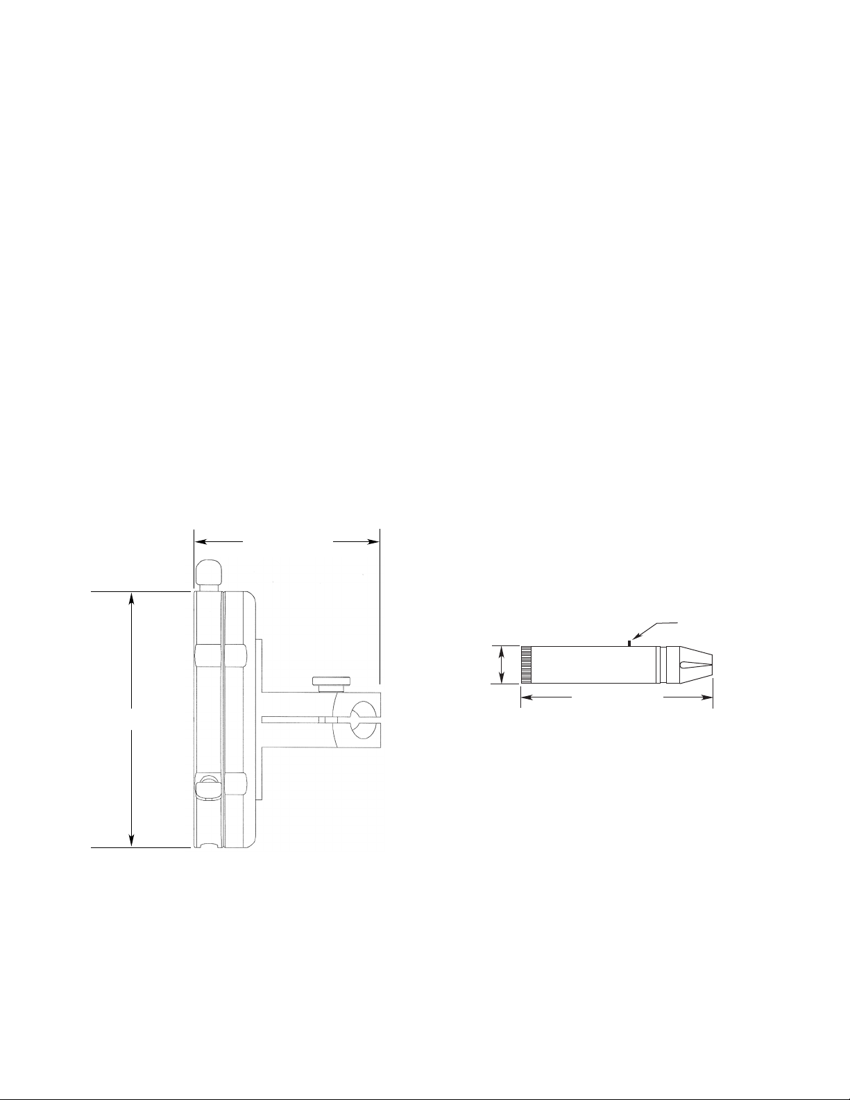
MOUNTING THE Q1201C LASER HOLDER
1. Mount the detector in accordance with the
applicable detector instruction manual to survey the
area requiring coverage.
2. Mount the Q1201C Laser Holder over the face of
the detector. Tighten the thumb screw to hold the
Q1201C securely in place.
DETERMINING THE CENTER OF THE
DETECTOR’S CONE OF VISION
To determine the exact center of the cone of vision:
1. Slide the Laser into the center mounting hole on the
Q1201C. Refer to Figure 1.
2. Turn the Laser on. DO NOT allow the Laser to
shine directly in eyes. The laser beam “dot”
indicates the center of the cone of vision. Adjust
the flame detector swivel position accordingly, and
tighten the swivel lock nut when the proper angle is
achieved.
NOTE
It may be necessary to dim lights or perform this
procedure at night in order to clearly see the
laser beam. This is especially true where bright
lights are present, in daylight, or where the cone
of vision is being tested at extended distances.
DETERMINING THE CONE OF VISION PERIMETER
To determine the perimeter or outer limits of the cone
of vision:
1. To test the 30 degree portion of the detector's cone
of vision, slide the Laser into the 30 degree hole.
To test the 45 degree portion of the detector's cone
of vision, slide the Laser into the 45 degree hole.
Tighten the appropriate thumb screw to hold the
Laser securely in place. Refer to Figure 1.
2. Turn the Laser on. DO NOT allow the Laser to
shine directly in eyes. The laser beam “dot”
indicates a point on the perimeter of the cone of
vision. Rotate the holder and observe the laser
beam to determine the perimeter of the cone of
vision.
3. Refer to Figure 4 for an illustration of the 30 degree
and 45 degree portions of the COV.
4. Adjust the flame detector swivel position
accordingly, and tighten the swivel lock nut when
the proper angle is achieved.
NOTE
The cone of vision perimeter indicated by the
Laser does not guarantee ame detection within
the perimeter in all cases, nor does it necessarily
exclude detection of ames outside the perimeter.
Flame detection within the eld of view is a
function of re size, re type, and distance.
The instruction manuals for the X-Series ame
detectors show how detection range for a given
re size decreases near the perimeter of the eld
of view. Refer to the FM Appendix section in the
applicable manual for details.
Contact Detector Electronics for additional
information.
5. Turn the Laser off and remove it from the holder
when testing is complete. Failure to turn off will
deplete the batteries. Remove the Q1201C Laser
Holder from the detector.
Figure 4—30 Degree and 45 Degree Portions
of the Detector's Cone of Vision
30°
30°
30 DEGREE
PORTION OF COV
45 DEGREE
PORTION OF COV
A2329
TOP OF DETECTOR
BAT TE RY IN STALL ATION
1. These batteries can be used in the Laser:
Duracell TR175 (1)
Duracell PX28L (1)
Duracell DL1/3N (2)
Eveready 357 (4).
2. Unscrew the battery cap and remove the old battery
(batteries).
3. Insert the new battery (batteries) with the polarity as
indicated in Figure 5.
4. Replace battery cap.
TROUBLESHOOTING
Refer to the items below to correct problems in the field.
If the problem cannot be corrected, return the unit to
Det-Tronics for repair.
1. Will not turn on. Check battery position. If correct,
replace battery.
2. Will not turn off. Return the Laser to Det-Tronics
for replacement of switch.
MAINTENANCE
If the Laser becomes dirty, wipe dirt off the outside
surfaces with a damp cloth. If the laser aperture is
dirty, use a spray bottle with water. Blow off any water
remaining on the lens. DO NOT clean or wipe the lens
with a cloth, tissue, cotton swab, etc.
DEVICE REPAIR AND RETURN
Prior to returning devices, a Return Materials
Authorization (RMA) number must be obtained. The
process for obtaining this number can be found on
the Det-Tronics website. You may also contact your
authorized local sales representative or Det-Tronics
Technical Support for assistance:
1.800.765.3473, ext.3 (M-F, 8 AM - 5 PM, Central
Prevailing Time)
RMA@Carrier.com
NOTE
Shipments received without an RMA number
clearly marked on the outside of the shipment will
be refused.
Pack the unit properly. Det-Tronics reserves
the right to apply a service charge for repairing
returned product damaged as a result of improper
packaging.
Return all equipment transportation prepaid to
the factory in Minneapolis.
ORDERING INFORMATION
When ordering, specify:
Part Number Description
007255-001 Q1201C Laser Holder for X-Series
Flame Detectors
006097-001 Laser
BATTERY
LASER
BATTERY CAP
A2326
Figure 5—Laser Battery
Environmental Protection
Waste electrical products should not be disposed of
with industrial and commercial waste. Please recycle
where facilities exist. Check with your Local Authority
or the local Detector Electronics office for recycling
advice.
Corporate Office
6901 West 110th Street
Minneapolis, MN 55438 USA
www.det-tronics.com
Phone: +1 952.941.6665
Toll-free: +1 800.765.3473
Fax: 952.829.8750
det-tronics@carrier.com
Specications subject to change without notice.
All trademarks are the property of their respective owners.
© 2020 Detector Electronics Corporation. All rights reserved.
Det-Tronics manufacturing system is certied to ISO 9001—
the world’s most recognized quality management standard.

This manual suits for next models

1

Other Carrier Measuring Instrument manuals

Carrier KW320 User manual

Carrier

Carrier KW320 User manual

Carrier Indoor Air Quality (IAQ) User manual

Carrier

Carrier Indoor Air Quality (IAQ) User manual

Carrier 2010-2A-ZI-20 Assembly instructions

Carrier

Carrier 2010-2A-ZI-20 Assembly instructions

Popular Measuring Instrument manuals by other brands

Hanna Instruments HI 93739 instruction manual

Hanna Instruments

Hanna Instruments HI 93739 instruction manual

Siemens 9810 Series user manual

Siemens

Siemens 9810 Series user manual

Keysight PXA N9030A Installation note

Keysight

Keysight PXA N9030A Installation note

Wohler RF 220 Hygrotemp manual

Wohler

Wohler RF 220 Hygrotemp manual

ORTEC 420 instruction manual

ORTEC

ORTEC 420 instruction manual

Hilti PX 10 operating instructions

Hilti

Hilti PX 10 operating instructions

Agilent Technologies B1500A Training manual

Agilent Technologies

Agilent Technologies B1500A Training manual

PCE Instruments PCE-CM 40 user manual

PCE Instruments

PCE Instruments PCE-CM 40 user manual

Dwyer Instruments DPMA-4 Series Installation and operating instructions

Dwyer Instruments

Dwyer Instruments DPMA-4 Series Installation and operating instructions

WIKA A2G-10 operating instructions

WIKA

WIKA A2G-10 operating instructions

Kikusui KJM6335 Operation manual

Kikusui

Kikusui KJM6335 Operation manual

Badger Meter RCM 2000 Installation and operation manual

Badger Meter

Badger Meter RCM 2000 Installation and operation manual

Vega VEGAFLEX 80 Series Supplementary instructions

Vega

Vega VEGAFLEX 80 Series Supplementary instructions

RDS CMM 100 user guide

RDS

RDS CMM 100 user guide

Clas Ohlson ST-171 instruction manual

Clas Ohlson

Clas Ohlson ST-171 instruction manual

KROHNE OPTIWAVE 5200 C/F Handbook

KROHNE

KROHNE OPTIWAVE 5200 C/F Handbook

Burkert 8012 Series operating instructions

Burkert

Burkert 8012 Series operating instructions

Tektronix 1502B Service manual

Tektronix

Tektronix 1502B Service manual

manuals.online logo
manuals.online logoBrands
  • About & Mission
  • Contact us
  • Privacy Policy
  • Terms and Conditions

Copyright 2025 Manuals.Online. All Rights Reserved.