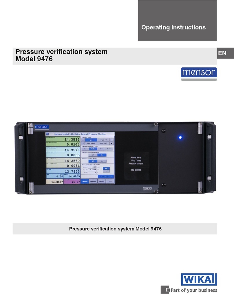
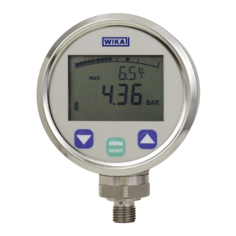
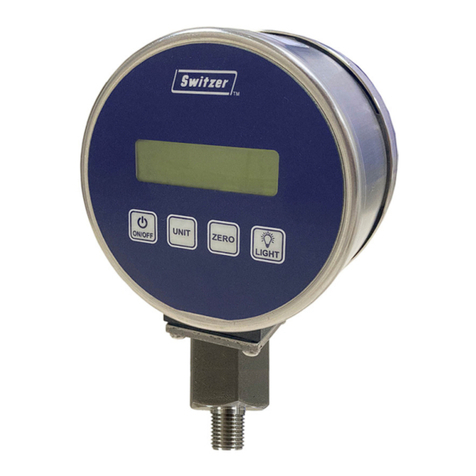
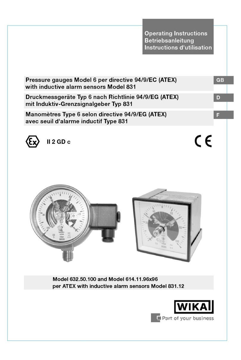
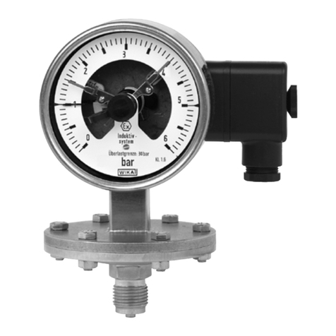
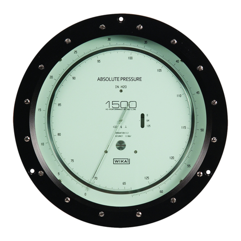
WIKA A2G-10 User manual

Operating instructions
Betriebsanleitung
Mode d‘emploi
Manuale d‘uso
EN
DE
FR
IT
Differential pressure gauges, models A2G-10, A2G-15
Differenzdruckmanometer, Typen A2G-10, A2G-15
Manomètres différentiels, types A2G-10, A2G-15
Manometri differenziali, modelli A2G-10, A2G-15
Fig. left: Model A2G-10
Fig. right: Model A2G-15 with output signal

EN
DE
FR
IT
2
40197319.05 02/2021 EN/DE/FR/IT
WIKA operating instructions models A2G-10, A2G-15
Operating instructions models A2G-10, A2G-15 Page 3 - 16
Betriebsanleitung Typen A2G-10, A2G-15 Seite 17 - 30
Mode d'emploi types A2G-10, A2G-15 Page 31 - 44
Manuale d‘uso modelli A2G-10, A2G-15 Pagina 45 - 58
© 05/2010 WIKA Alexander Wiegand SE & Co. KG
All rights reserved. / Alle Rechte vorbehalten.
WIKA®is a registered trademark in various countries.
WIKA®ist eine geschützte Marke in verschiedenen Ländern.
Prior to starting any work, read the operating instructions!
Keep for later use!
Vor Beginn aller Arbeiten Betriebsanleitung lesen!
Zum späteren Gebrauch aufbewahren!
Lire le mode d‘emploi avant de commencer toute opération !
A conserver pour une utilisation ultérieure !
Prima di iniziare ad utilizzare lo strumento, leggere il manuale d‘uso!
Conservare per future consultazioni!

EN
40197319.05 02/2021 EN/DE/FR/IT
WIKA operating instructions models A2G-10, A2G-15 3
Contents
Contents
1. General information 4
2. Design and function 5
3. Safety 6
4. Transport, packaging and storage 8
5. Commissioning, operation 8
6. Maintenance and cleaning 12
7. Dismounting, return and disposal 13
8. Specifications 14
9. Accessories 16

EN
40197319.05 02/2021 EN/DE/FR/IT
WIKA operating instructions models A2G-10, A2G-154
1. General information
■
The differential pressure gauge described in the operating instructions has been
designed and manufactured using state-of-the-art technology. All components
are subject to stringent quality and environmental criteria during production. Our
management systems are certified to ISO 9001 and ISO 14001.
■
These operating instructions contain important information on handling the instrument.
Working safely requires that all safety instructions and work instructions are observed.
■
Observe the relevant local accident prevention regulations and general safety
regulations for the instrument's range of use.
■
The operating instructions are part of the product and must be kept in the immediate
vicinity of the instrument and readily accessible to skilled personnel at any time. Pass
the operating instructions on to the next operator or owner of the instrument.
■
Skilled personnel must have carefully read and understood the operating instructions
prior to beginning any work.
■
The general terms and conditions contained in the sales documentation shall apply.
■
Subject to technical modifications.
■
Further information:
- Internet address: www.wika.de / www.wika.com
- Relevant data sheet: PM 07.40 and PV 17.40
- Application consultant: Tel.: +49 9372 132-0
Fax: +49 9372 132-406
info@wika.de
1. General information

EN
40197319.05 02/2021 EN/DE/FR/IT
WIKA operating instructions models A2G-10, A2G-15 5
2. Design and function
2.1 Overview
Pressure measuring system
Threaded bezel
Built-in case
Add-on case
Cable gland
2.2 Description
The model A2G-10 and A2G-15 differential pressure gauges are used for monitoring
the differential pressure in ventilation and air-conditioning applications.The measuring
ranges cover from 0 … 100 Pa to 0 … 6,000 Pa. Plus/minus ranges can be fulfilled from
-50 … +50 Pa to -1,500 … +1,500 Pa.
Electrical output signals of the model A2G-15 for both measurands (DC 0 … 10 V or
4 … 20 mA) enable the direct connection to control systems or the building automation
system.
2.3 Scope of delivery
■
Differential pressure gauge
■
Case (built-in or add-on)
■
Threaded pressure connection
Cross-check scope of delivery with delivery note.
Model A2G-10 Model A2G-15,
with electrical output signal
2. Design and function

EN
40197319.05 02/2021 EN/DE/FR/IT
WIKA operating instructions models A2G-10, A2G-156
3. Safety
3.1 Explanation of symbols
WARNING!
... indicates a potentially dangerous situation that can result in serious injury
or death, if not avoided.
CAUTION!
... indicates a potentially dangerous situation that can result in light injuries or
damage to property or the environment, if not avoided.
DANGER!
... identifies hazards caused by electrical power. Should the safety
instructions not be observed, there is a risk of serious or fatal injury.
WARNING!
... indicates a potentially dangerous situation that can result in burns, caused
by hot surfaces or liquids, if not avoided.
Information
... points out useful tips, recommendations and information for efficient and
trouble-free operation.
3.2 Intended use
This pressure gauge is designed for measuring very low pressures in dry, clean,
non-aggressive gases, primarily air.
The technical specifications contained in these operating instructions must be observed.
Improper handling or operation of the instrument outside of its technical specifications
requires the instrument to be taken out of service immediately and inspected by an
authorised WIKA service engineer.
The instrument has been designed and built solely for the intended use described here,
and may only be used accordingly.
The manufacturer shall not be liable for claims of any type based on operation contrary to
the intended use.
3. Safety

EN
40197319.05 02/2021 EN/DE/FR/IT
WIKA operating instructions models A2G-10, A2G-15 7
3.3 Improper use
WARNING!
Injuries through improper use
Improper use of the instrument can lead to hazardous situations and injuries.
▶
Refrain from unauthorised modifications to the instrument.
▶
Do not use the instrument within hazardous areas.
Any use beyond or different to the intended use is considered as improper use.
3.4 Personnel qualification
WARNING!
Risk of injury should qualification be insufficient
Improper handling can result in considerable injury and damage to property.
▶
The activities described in these operating instructions may only be carried
out by skilled personnel who have the qualifications described below.
Skilled personnel
Skilled personnel, authorised by the operator, are understood to be personnel who, based
on their technical training, knowledge of measurement and control technology and on
their experience and knowledge of country-specific regulations, current standards and
directives, are capable of carrying out the work described and independently recognising
potential hazards.
3.5 Labelling, safety marks
Product label (example)
Model Supply voltage
Measuring range Serial number
Output signal
Before mounting and commissioning the instrument, ensure you read the
operating instructions!
Type: A2G-50
Range: -250 ... +250 Pa
Output: 0 ... 10 V / 4 ... 20 mA
Supply: DC 24 V / AC 24 V ±10 % < 1 W
Made in EU E-Nr. 66209848
3. Safety

EN
40197319.05 02/2021 EN/DE/FR/IT
WIKA operating instructions models A2G-10, A2G-158
4. Transport, packaging and storage
4.1 Transport
Check the instrument for any damage that may have been caused by transport.
Obvious damage must be reported immediately.
CAUTION!
Damage through improper transport
With improper transport, a high level of damage to property can occur.
▶
When unloading packed goods upon delivery as well as during internal
transport, proceed carefully and observe the symbols on the packaging.
▶
With internal transport, observe the instructions in chapter 4.2 “Packaging
and storage”.
4.2 Packaging and storage
Do not remove packaging until just before mounting.
Keep the packaging as it will provide optimum protection during transport (e.g. change in
installation site, sending for repair).
Permissible conditions at the place of storage:
■
Storage temperature: 0 ... 70 °C
■
Humidity: 35 ... 85 % relative humidity (no condensation)
5. Commissioning, operation
5.1 Installation and mechanical connection
In accordance with the general technical regulations for pressure measuring instruments
(e.g. EN 837-2 “Selection and installation recommendations for pressure gauges”).
air2guide standard gauges are calibrated in vertical position and should be installed in the
same position to avoid loss of class accuracy. If a different installation position is required
for air2guide instruments, please specify when ordering. Instruments with high measuring
ranges can be installed in a different, non-vertical mounting position by simply adjusting
the zero point.
4. Transport, packaging ... / 5. Commissioning, operation
EN
40197319.05 02/2021 EN/DE/FR/IT
WIKA operating instructions models A2G-10, A2G-15 9
5. Commissioning, operation
To screw down pierce three
prepunched holes by means
of a screwdriver
It is not necessary to pierce holes
when carrying out assembly
using a threaded bezel
or
Wall mounting, lower mount
Panel mounting, back mount

EN
40197319.05 02/2021 EN/DE/FR/IT
WIKA operating instructions models A2G-10, A2G-1510
After fitting the measuring element into the case it can be moved in a clockwise and
counterclockwise direction respectively for 15 angular degrees in order to ensure precise
horizontal positioning of the instrument.
5. Commissioning, operation
Detailed mounting steps for panel mounting
Detailed mounting steps for wall mounting

EN
40197319.05 02/2021 EN/DE/FR/IT
WIKA operating instructions models A2G-10, A2G-15 11
5.2 Commissioning
■
During the commissioning process pressure surges must be avoided at all costs.
■
Protect pressure gauges from contamination, high temperature changes and vibrations.
■
Use the pressure gauge only if the diaphragm is undamaged and if it is in perfect
condition with regard to safety.
■
Mounting of the pressure connection according to affixed symbols:
⊕ high pressure
⊖ low pressure
5.3 Output signal, model A2G-15
Output signal, model A2G-15
Supply voltage UBDC 15 … 35 V
Measurement accuracy of sensor ±3 % of end value of measuring range
Electrical connection M12 cable gland with screw terminals
5.4 Zero point setting
In general, the zero point should only be checked and adjusted after the system has been
depressurised.
Mechanical and electrical zero point
If there is a deviation from the zero point (in depressurised condition), a zero point
correction can be carried out via the zero point setting (screw).The mechanical as well as
the electrical zero point can be adjusted simultaneously by turning the zero point screw (at
the front side of the instrument).
1
2
3
V
DC 0 … 10 V, 3-wire
GND
0 … 10 V
DC 24 V
UB
1
2
3A
UB
4 … 20 mA, 2-wire
4 … 20 mA
4 … 20 mA
5. Commissioning, operation
EN
40197319.05 02/2021 EN/DE/FR/IT
WIKA operating instructions models A2G-10, A2G-1512
6. Maintenance and cleaning
For contact details see chapter 1 “General information” or the back page of
the operating instructions.
6.1 Maintenance
This instrument is maintenance-free.
Repairs must only be carried out by the manufacturer or appropriately qualified skilled
personnel.
6.2 Cleaning
CAUTION!
Physical injuries and damage to property and the environment
Improper cleaning may lead to physical injuries and damage to property and
the environment. Residual media in the dismounted instrument can result in a
risk to persons, the environment and equipment.
▶
Carry out the cleaning process as described below.
1. Before cleaning, correctly disconnect the instrument from the pressure supply, switch it
off and disconnect it from the mains.
2. Use the requisite protective equipment.
3. Clean the instrument with a moist cloth.
Electrical connections must not come into contact with moisture!
CAUTION!
Damage to the instrument
Improper cleaning may lead to damage to the instrument!
▶
Do not use any aggressive cleaning agents.
▶
Do not use any hard or pointed objects for cleaning.
4. Wash or clean the dismounted instrument, in order to protect persons and the
environment from exposure to residual media.
6. Maintenance and cleaning

EN
40197319.05 02/2021 EN/DE/FR/IT
WIKA operating instructions models A2G-10, A2G-15 13
7. Dismounting, return and disposal
7.1 Dismounting
WARNING!
Physical injuries and damage to property and the environment
through residual media
Upon contact with hazardous media (e.g. oxygen, acetylene, flammable
or toxic substances), harmful media (e.g. corrosive, toxic, carcinogenic,
radioactive), and also with refrigeration plants and compressors, there is a
danger of physical injuries and damage to property and the environment.
▶
Before storage of the dismounted instrument (following use) wash or
clean it, in order to protect persons and the environment from exposure to
residual media.
▶
Observe the information in the material safety data sheet for the
corresponding medium.
7.2 Return
Strictly observe the following when shipping the instrument:
All instruments delivered to WIKA must be free from any kind of hazardous substances
(acids, bases, solutions, etc.) and must therefore be cleaned before being returned.
WARNING!
Physical injuries and damage to property and the environment
through residual media
Residual media in the dismounted differential pressure gauge can result in a
risk to persons, the environment and equipment.
7.3 Disposal
Incorrect disposal can put the environment at risk.
Dispose of instrument components and packaging materials in an environmentally
compatible way and in accordance with the country-specific waste disposal regulations.
Do not dispose of with household waste. Ensure a proper disposal in
accordance with national regulations.

EN
40197319.05 02/2021 EN/DE/FR/IT
WIKA operating instructions models A2G-10, A2G-1514
8. Specifications
Differential pressure gauge, models A2G-10 and A2G-15
Version
■
Standard version
■
Silicone-free version
Nominal size in mm 110
Measuring range
■
0 ... 100 Pa to 0 ... 6,000 Pa
■
-50 ... +50 Pa to -1,500 ... +1,500 Pa
Other plus/minus ranges on request
Unit
■
Pa
■
kPa
■
inWC
■
mmWC
■
mbar
Scale
■
Single scale
■
Dual scale
Accuracy class
Span ≥ 250 Pa 3.0
Span 101 ... 249 Pa 5.0
Span ≤ 100 Pa 10.0
Process connection G ⅛ female
Threaded pressure connection for measuring hoses
with inner diameter 4 ... 6 mm (see “Accessories”)
Movement Contact-free transmission (SWISS MOVEMENT)
Materials
Case components Plastic, glass-fibre reinforced
Separating diaphragm
■
Silicone
■
EPDM (with silicone-free version)
Window Polycarbonate (UV stabilised)
Dial Aluminium
Pointer Plastic, black
Mark pointer
■
Without
■
Plastic, red
Medium
■
Air
■
Non-flammable and non-aggressive gases
Permissible temperature
Medium Model A2G-10 -20 ... +50 °C [-4 ... +122 °F]
Model A2G-15 -16 ... +50 °C [-3 ... +122 °F]
Ambient -30 ... +80 °C [-22 ... +176 °F]
8. Specifications

EN
40197319.05 02/2021 EN/DE/FR/IT
WIKA operating instructions models A2G-10, A2G-15 15
Differential pressure gauge, models A2G-10 and A2G-15
Max. working pressure (static pressure) 20 kPa
Ingress protection per IEC/EN 60529
■
IP54
■
IP65
Weight (pressure measuring system)
Model A2G-10 235 g
Model A2G-15 255 g
8. Specifications

EN
40197319.05 02/2021 EN/DE/FR/IT
WIKA operating instructions models A2G-10, A2G-1516
9. Accessories
9. Accessories
Description Order number
Process connections
Threaded pressure connection, straight, Ø 4 ... 6 mm 40423607
Threaded pressure connection, angled, Ø 4 ... 6 mm 40423526
With mounting thread G ⅛ for pipes 6.35 mm [¼"] 40232867
Combi hose connection for pressure measuring hoses
Ø 4 ... 7 mm
40232484
Static duct probes with combi hose connection for
pressure measuring hoses Ø 4 ... 7 mm
Insertion length 100 mm 40232981
Insertion length 150 mm 40232999
Insertion length 200 mm 40233006
Measuring hoses
PVC hose, inner diameter 4 mm, roll at 25 m 40217841
PVC hose, inner diameter 6 mm, roll at 25 m 40217850
Silicone hose, inner diameter 4 mm, roll at 25 m 40208940
Silicone hose, inner diameter 6 mm, roll at 25 m 40208958
Duct connectors for measuring hoses Ø 4 ... 6 mm 40217507
Weather protection 40241564

40197319.05 02/2021 EN/DE/FR/IT
DE
WIKA Betriebsanleitung Typen A2G-10, A2G-15 17
Inhalt
Inhalt
1. Allgemeines 18
2. Aufbau und Funktion 19
3. Sicherheit 20
4. Transport, Verpackung und Lagerung 22
5. Inbetriebnahme, Betrieb 22
6. Wartung und Reinigung 26
7. Demontage, Rücksendung und Entsorgung 27
8. Technische Daten 28
9. Zubehör 30

40197319.05 02/2021 EN/DE/FR/IT
DE
WIKA Betriebsanleitung Typen A2G-10, A2G-1518
1. Allgemeines
■
Das in der Betriebsanleitung beschriebene Differenzdruckmanometer wird nach
dem aktuellen Stand der Technik konstruiert und gefertigt. Alle Komponenten unter-
liegen während der Fertigung strengen Qualitäts- und Umweltkriterien. Unsere
Managementsysteme sind nach ISO 9001 und ISO 14001 zertifiziert.
■
Diese Betriebsanleitung gibt wichtige Hinweise zum Umgang mit dem Gerät.Voraus-
setzung für sicheres Arbeiten ist die Einhaltung aller angegebenen Sicherheitshinweise
und Handlungsanweisungen.
■
Die für den Einsatzbereich des Gerätes geltenden örtlichen
Unfallverhütungsvorschriften und allgemeinen Sicherheitsbestimmungen einhalten.
■
Die Betriebsanleitung ist Produktbestandteil und muss in unmittelbarer Nähe des
Gerätes für das Fachpersonal jederzeit zugänglich aufbewahrt werden. Betriebsanlei-
tung an nachfolgende Benutzer oder Besitzer des Gerätes weitergeben.
■
Das Fachpersonal muss die Betriebsanleitung vor Beginn aller Arbeiten sorgfältig
durchgelesen und verstanden haben.
■
Es gelten die allgemeinen Geschäftsbedingungen in den Verkaufsunterlagen.
■
Technische Änderungen vorbehalten.
■
Weitere Informationen:
- Internet-Adresse: www.wika.de / www.wika.com
- Zugehöriges Datenblatt: PM 07.40 und PV 17.40
- Anwendungsberater: Tel.: +49 9372 132-0
Fax: +49 9372 132-406
info@wika.de
1. Allgemeines

40197319.05 02/2021 EN/DE/FR/IT
DE
WIKA Betriebsanleitung Typen A2G-10, A2G-15 19
2. Aufbau und Funktion
2.1 Überblick
Druckmesssystem
Schraubring
Einbaugehäuse
Aufbaugehäuse
Kabelverschraubung
2.2 Beschreibung
Die Differenzdruckmanometer Typen A2G-10 und A2G-15 werden zur Überwachung des
Differenzdruckes in der Luft- und Klimatechnik verwendet. Die Messbereiche reichen
von 0 ... 100 Pa bis zu 0 ... 6.000 Pa. Plus-/Minusbereiche können von -50 ... +50 Pa bis
-1.500 ... +1.500 Pa erfüllt werden.
Elektrische Ausgangssignale des Typ A2G-15 für beide Messgrößen (DC 0 … 10 V oder
4 ... 20 mA) erlauben den direkten Anschluss an Steuer-/Regelsysteme oder die Gebäu-
deautomation.
2.3 Lieferumfang
■
Differenzdruckmanometer
■
Gehäuse (für den Ein- oder Aufbau)
■
Einschraubstutzen
Lieferumfang mit dem Lieferschein abgleichen.
Typ A2G-10 Typ A2G-15,
mit elektrischem Ausgangssignal
2. Aufbau und Funktion

40197319.05 02/2021 EN/DE/FR/IT
DE
WIKA Betriebsanleitung Typen A2G-10, A2G-1520
3. Sicherheit
3.1 Symbolerklärung
WARNUNG!
... weist auf eine möglicherweise gefährliche Situation hin, die zum Tod oder
zu schweren Verletzungen führen kann, wenn sie nicht gemieden wird.
VORSICHT!
... weist auf eine möglicherweise gefährliche Situation hin, die zu geringfügi-
gen oder leichten Verletzungen bzw. Sach- und Umweltschäden führen kann,
wenn sie nicht gemieden wird.
GEFAHR!
... kennzeichnet Gefährdungen durch elektrischen Strom. Bei Nichtbeach-
tung der Sicherheitshinweise besteht die Gefahr schwerer oder tödlicher
Verletzungen.
WARNUNG!
... weist auf eine möglicherweise gefährliche Situation hin, die durch heiße
Oberflächen oder Flüssigkeiten zu Verbrennungen führen kann, wenn sie
nicht gemieden wird.
Information
... hebt nützliche Tipps und Empfehlungen sowie Informationen für einen
effizienten und störungsfreien Betrieb hervor.
3.2 Bestimmungsgemäße Verwendung
Dieses Manometer dient zum Messen von sehr niedrigen Drücken bei trockenen, saube-
ren, nicht aggressiven Gasen, hauptsächlich Luft.
Die technischen Spezifikationen in dieser Betriebsanleitung sind einzuhalten. Eine
unsachgemäße Handhabung oder ein Betreiben des Gerätes außerhalb der technischen
Spezifikationen macht die sofortige Stilllegung und Überprüfung durch einen autorisierten
WIKA-Servicemitarbeiter erforderlich.
Das Gerät ist ausschließlich für den hier beschriebenen bestimmungsgemäßen Verwen-
dungszweck konzipiert und konstruiert und darf nur dementsprechend verwendet werden.
Ansprüche jeglicher Art aufgrund von nicht bestimmungsgemäßer Verwendung sind
ausgeschlossen.
3. Sicherheit
This manual suits for next models
1
Table of contents
Languages:
Other WIKA Measuring Instrument manuals

WIKA
WIKA PG23HP Series User manual

WIKA
WIKA SENSeOR AMS01 User manual

WIKA
WIKA 821 User manual

WIKA
WIKA 632.50 User manual

WIKA
WIKA 3 Series User manual

WIKA
WIKA TFT35 User manual

WIKA
WIKA DELTA-trans DPGT40 User manual

WIKA
WIKA A-AI-1 User manual

WIKA
WIKA CTD4000 User manual

WIKA
WIKA CPG2300 Series User manual
Popular Measuring Instrument manuals by other brands

Life technologies
Life technologies Countess Series quick reference

LI-COR
LI-COR LI-600 quick start guide

GF
GF 3-2630-X manual

Industrial Data Systems
Industrial Data Systems IDS 430 Installation/Calibration/Operation

Wet Labs
Wet Labs ac-s user guide

Camille Bauer
Camille Bauer SINEAX DM5000 Device handbook