Carrier i-Vu XT Installation manual

i
i-
-V
Vu
u®
®
X
XT
T
R
Ro
ou
ut
te
er
r
I
In
ns
st
ta
al
ll
la
at
ti
io
on
n
a
an
nd
d
S
St
ta
ar
rt
t-
-u
up
p
G
Gu
ui
id
de
e
CARRIER CORPORATION ©2018
A member of the United Technologies Corporation family · Stock symbol UTX · Catalog No. 11-808-580-01 · 10/2/2018

Verify that you have the most current version of this document from
www.hvacpartners.com
or your local Carrier
office.
Important changes are listed in
Document revision history
at the end of this document.
CARRIER CORPORATION ©2018. All rights reserved throughout the world. i-Vu is a registered trademark of Carrier
Corporation. All other trademarks are the property of their respective owners.

Contents
What is the i-Vu® XT Router? ..................................................................................................................................... 1
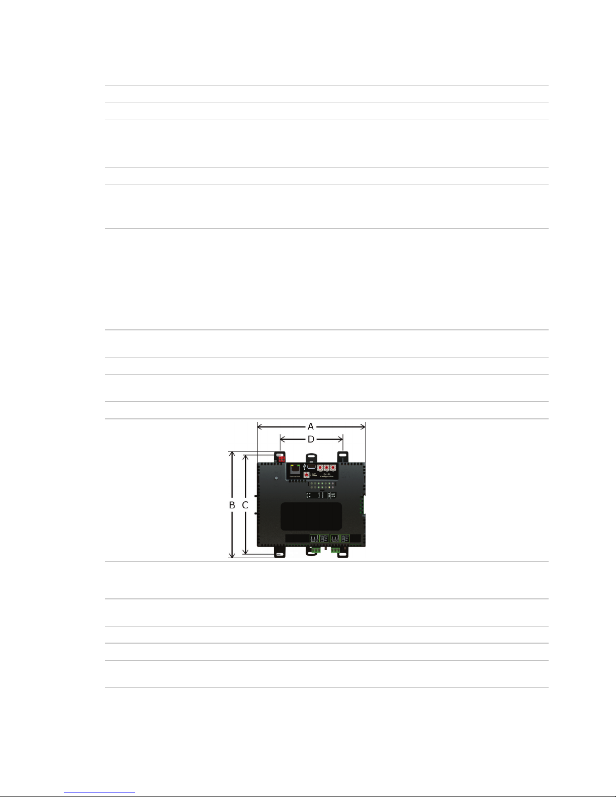
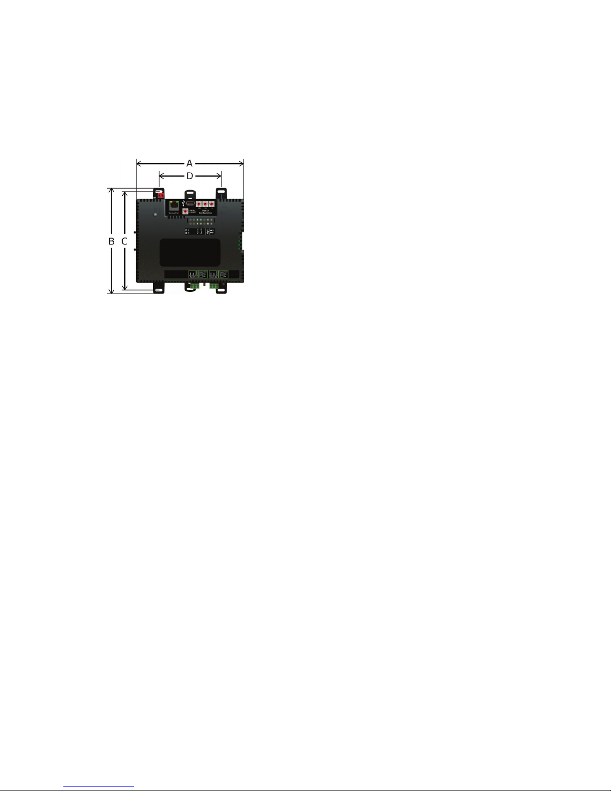
Specifications ........................................................................................................................................................1
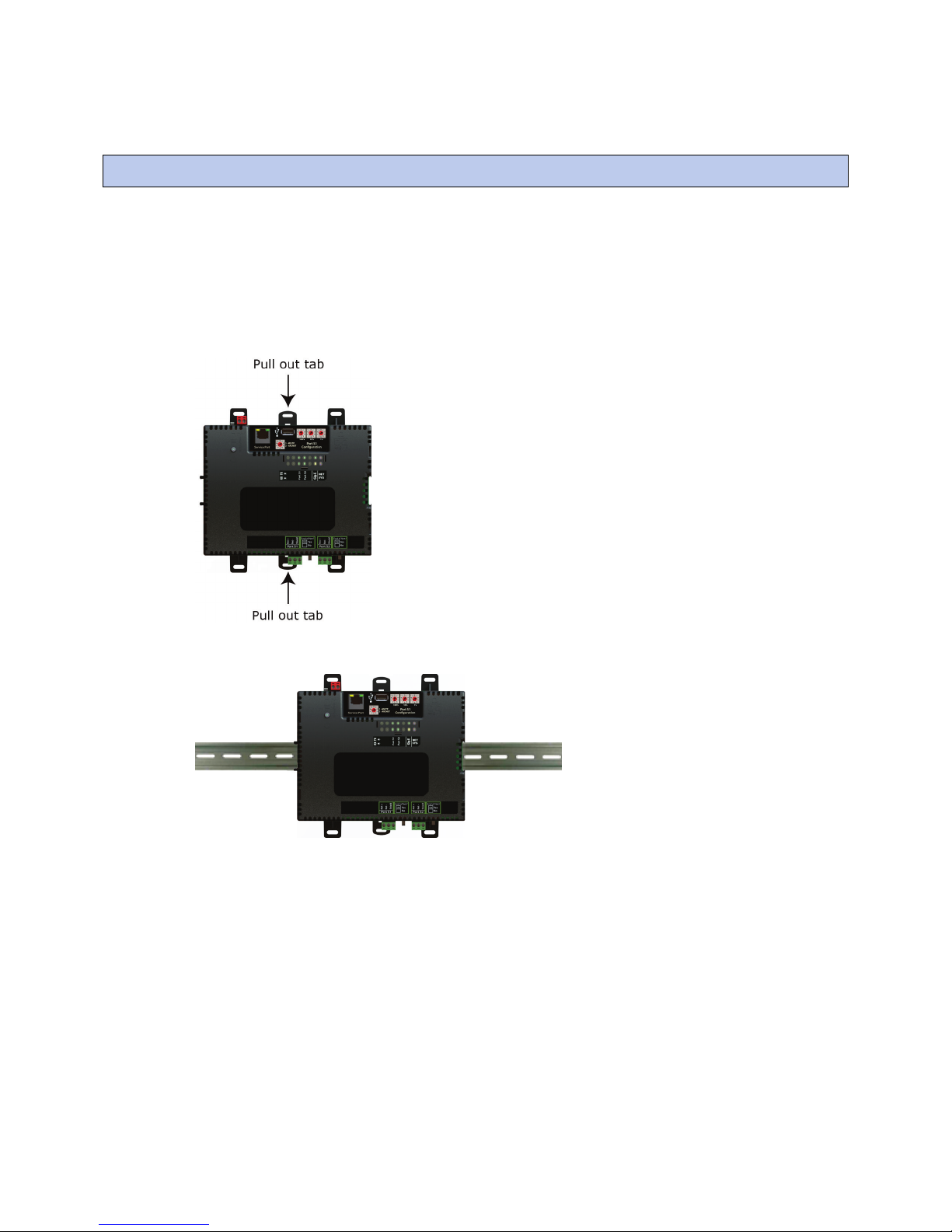
To mount the i-Vu® XT Router.................................................................................................................................... 4
Wiring for power .......................................................................................................................................................... 6
To wire for power ..................................................................................................................................................6
Addressing the i-Vu® XT Router ................................................................................................................................. 7
Rotary switch settings..........................................................................................................................................7
To set the IP address............................................................................................................................................8
To set the Port S1 address and baud rate..................................................................................................... 10
To set the Port S2 address and baud rate..................................................................................................... 10
Wiring for communications ......................................................................................................................................11
Wiring specifications......................................................................................................................................... 11
To connect the i-Vu® XT Router to the Ethernet........................................................................................... 12
To wire to a BACnet/ARCNET network........................................................................................................... 13
To wire to a BACnet MS/TP network .............................................................................................................. 13
Find and upload in the i-Vu® interface ....................................................................................................................14
Adjusting the i-Vu® XT Router driver properties .....................................................................................................15
Driver ................................................................................................................................................................... 15
Device .................................................................................................................................................................. 15
Notification Classes........................................................................................................................................... 16
Calendars ............................................................................................................................................................ 17
Common and Specific Alarms ......................................................................................................................... 18
BACnet router properties.................................................................................................................................. 18
BACnet firewall................................................................................................................................................... 18
Network Diagnostics - Statistics...................................................................................................................... 19
Network Diagnostics - Packet Capture........................................................................................................... 21
Communication Status ..................................................................................................................................... 23
To set up Network Statistic trends.................................................................................................................. 23
To set up the controller through the Service Port ...................................................................................................25
ModStat tab ........................................................................................................................................................ 25
Device tab ........................................................................................................................................................... 26
Ports tab.............................................................................................................................................................. 26
BACnet tab.......................................................................................................................................................... 27
Security tab......................................................................................................................................................... 29
Troubleshooting .........................................................................................................................................................30
LEDs ..................................................................................................................................................................... 30
To get a Module Status report ......................................................................................................................... 32
To get a Device Log ........................................................................................................................................... 32
To get the i-Vu® XT Router's serial number .................................................................................................. 33
To replace the i-Vu® XT Router's fuse............................................................................................................ 33
To take the i-Vu® XT Router out of service.................................................................................................... 35
Compliance ................................................................................................................................................................36
FCC Compliance................................................................................................................................................. 36
CE Compliance ................................................................................................................................................... 36
Industry Canada Compliance........................................................................................................................... 36
BACnet Compliance........................................................................................................................................... 36
Appendix - Module Status field descriptions ...........................................................................................................37
Document revision history ........................................................................................................................................39


i-Vu® XT Router CARRIER CORPORATION ©2018
Installation and Start-up Guide All rights reserved
1
The i-Vu® XT Router:
•Provides BACnet routing between any supported BACnet communication types
•Supports DHCP IP addressing
•Can serve as a BACnet Broadcast Management Device (BBMD)
•Supports Foreign Device Registration (FDR)
•Works with the i-Vu® v6.5 or later system
The i-Vu® XT Router has 3 physical BACnet communication ports:
Port type
For routing this type of
communication...
At...
10/100/1000 Mbps Ethernet BACnet/IP and/or
BACnet/Ethernet
10, 100, or 1000 Mbps (1 Gbps)
High-speed EIA485 port BACnet/ARCNET
or
BACnet/MSTP
156 Kbps
9.6 to 115.2 Kbps
Electrically isolated EIA485 port BACnet/MSTP 9.6 to 115.2 Kbps
The i-Vu® XT Router also has a:
•10/100 Mbps Ethernet Service Port for configuring, commissioning, and troubleshooting
•USB port for recovery
Specifications
Driver drv_fwex_< version >.driverx
Power 24 Vac ±10%, 50–60 Hz, 50 VA
26 Vdc ±10%, 15 W
Gig-E port 10/100/1000 BaseT Ethernet port for BACnet/IP and/or BACnet/Ethernet
communication on the Ethernet at 10, 100, or 1000 Mbps, full duplex
Port S1 For communication with either of the following:
•A BACnet ARCNET network at 156 kbps
•A BACnet MS/TP network at 9600 to 115200 bps
This port's
End of Net?
switch can be set to
Yes
to terminate the network segment.
Port S2 For communication with a BACnet MS/TP network at 9600 to 115200 bps. This
port's
End of Net?
switch can be set to
Yes
to terminate the network segment.
Service Port Ethernet port at 10 or 100 Mbps for system start-up and troubleshooting
What is the i-Vu® XT Router?

What is the i-Vu® XT Router?
i-Vu® XT Router CARRIER CORPORATION ©2018
Installation and Start-up Guide All rights reserved
2
USB port USB 2.0 host port for device recovery
Microprocessor 32-bit ARM Cortex-A8, 600MHz, processor with multi-level cache memory
Memory 16 GBs eMMC Flash memory (120 MB available for use) and 256 MB DDR3
DRAM.
User data is archived to non-volatile Flash memory when parameters are changed,
every 90 seconds, and when the firmware is deliberately shutdown or restarted.
Real-time clock Real-time clock keeps track of time in the event of a power failure for up to 3 days
Protection Device is protected by a replaceable, fast acting, 250 Vac, 2A, 5mm x 20mm glass
fuse.
The power and network ports comply with the EMC requirements EN50491-5-2.
LED status indicators
•Tricolor NET LED to show network status
•Tricolor
SYS
LED to show system status
•A
TX
(Transmit) and
RX
(Receive) LED for the following ports:
•Gig-E
•Port S1
•Port S2
See LEDs (page 30).
Environmental operating
range
32 to 140°F (0 to 60°C), 10–90% relative humidity, non-condensing
Physical Fire-retardant plastic ABS, UL94-5VA
Terminal blocks and
connectors
Screw-type terminal blocks.
0.2 in (5.08 mm) pitch connectors
Mounting 35mm DIN rail mounting or screw mounting
Overall dimensions A:
B:
Depth:
7.1 in. (18.03 cm)
6.95 in. (17.65 cm)
2.79 in. (7.09 cm)
Screw mounting dimensions C:
D:
6.45 in (16.38 cm)
4.1 in. (10.4 cm)
Recommended panel depth 6 in. (15.24 cm) minimum
Weight 1 lb. 1 oz. (0.482 kg)
BACnet Support Conforms to the BACnet Router (B-R-TR) Standard Device Profile as defined in
ANSI/ASHRAE Standard 135-2012 (BACnet) Annex L, Protocol Revision 9

What is the i-Vu® XT Router?
i-Vu® XT Router CARRIER CORPORATION ©2018
Installation and Start-up Guide All rights reserved
3
Compliance
United States of America:
FCC compliant to Title CFR47, Chapter 1, Subchapter A, Part 15, Subpart B, Class
A; UL Listed to UL 916, PAZX, Energy Management Equipment
Canada:
Industry Canada Compliant, ICES-003, Class A
cUL Listed UL 916, PAZX7, Energy Management Equipment
Europe: Mark
EN50491-5-2:2009; Part 5-2: EMC requirements for HBES/BACS used in
residential, commercial and light industry environment
EN50491-3:2009, Part 3: Electrical safety requirements for Home and Building
Electronic Systems (HBES) and Building Automation and Control Systems (BACS)
Low Voltage Directive: 2014/35/EU
RoHS Compliant: 2011/65/EU
Australia and New Zealand:
C-Tick Mark, AS/NZS 61000-6-3

To mount the i-Vu® XT Router
i-Vu® XT Router CARRIER CORPORATION ©2018
Installation and Start-up Guide All rights reserved
4
The i-Vu® XT Router must be mounted in a metal enclosure or cabinet which is properly rated for the location
where it is being installed.
DIN rail mount
1 Push down and pull out the center tabs shown below to clear the din rail trough on the back of the router.
2 Place the router on the DIN rail so that the rail is in the trough on the back of the router.
3 Push the center tabs towards the router until you hear them click.
4 Pull gently on the router to verify that it is locked in place.
To mount the i-Vu® XT Router

To mount the i-Vu® XT Router
i-Vu® XT Router CARRIER CORPORATION ©2018
Installation and Start-up Guide All rights reserved
5
Screw Mount
Leave about 2 in. (5 cm) on each side of the router for wiring.
Insert #6 screws through the mounting holes. Use no more than 8 in.lbs. torque to secure plastic tab to mounting
surface.
A:
B:
C:
D:
Depth:
7.1 in. (18.03 cm)
6.95 in. (17.65 cm)
6.45 in. (16.38 cm)
4.1 in. (10.4 cm)
2.79 in (7.09 cm)

Wiring for power
i-Vu® XT Router CARRIER CORPORATION ©2018
Installation and Start-up Guide All rights reserved
6
WARNING
Do not apply line voltage (mains voltage) to the router's ports and terminals.
CAUTIONS
•The i-Vu® XT Router is powered by a Class 2 power source. Take appropriate isolation measures when
mounting it in a control panel where non-Class 2 circuits are present.
•Carrier controllers can share a power supply as long as you:
•Maintain the same polarity.
•Use the power supply only for Carrier controllers.
To wire for power
1 Make sure the i-Vu® XT Router’s power switch is in the
OFF
position to prevent it from powering up before
you can verify the correct voltage.
2 Remove power from the power supply.
3 Pull the red screw terminal connector from the router's power terminals labeled
24 Vac/Vdc
(
+/-
).
4 Connect the power supply's wires to the red screw terminal connector.
5 Connect an 18 AWG or larger wire from the power supply's negative (-) terminal to earth ground. This wire
must not exceed 12 in. (30.5 cm).
6 Apply power to the power supply.
7 Measure the voltage at the red screw terminal connector to verify that the voltage is within the operating
range of 20 to 30 Vac or 23.4 to 30 Vdc.
8 Insert the red screw terminal connector into the router's power terminals.
9 To verify the polarity of the wiring, measure the voltage from the negative terminal of the red screw terminal
connector to a nearby ground. The reading should be 0V.
10 Turn on the router's power switch.
11 Verify that the LED on top of the router is on.
12 Measure the voltage at the red screw terminal connector to verify that the voltage is within the operating
range of 20 to 30 Vac or 23.4 to 30 Vdc.
Wiring for power

Addressing the i-Vu® XT Router
i-Vu® XT Router CARRIER CORPORATION ©2018
Installation and Start-up Guide All rights reserved
7
Set this port's address ...
In this location...
See...
IP Service Port To set the IP address
Port S1 On the router's
rotary switches
To set the Port S1 address and baud rate (page
10)
Port S2 Service Port To set the Port S2 address and baud rate (page
10)
To access the controller setup through the
Service Port
:
1 Connect an Ethernet cable from a computer to the router as shown below.
2 If your computer uses a static IP address, set the address to 169.254.1.x, where x is 2 or greater. If it uses a
DHCP address, leave the address as it is.
3 Turn off the computer's Wi-Fi if it is on.
4 Open a web browser on the computer.
5 Navigate to http://local.access or http://169.254.1.1 to see the controller setup pages.
See To set up the controller through the Service Port (page 25) for general information on using the controller
setup pages.
Rotary switch settings
Rotary switch settings (see example below) are used to determine the following items in your system, so you
should plan carefully before setting the switches.
•If you use a
Default IP address
, the final octet is the number created by the three rotary switch settings (must
be a unique number from 1 to 253). See To set the IP address (page 8).
Addressing the i-Vu® XT Router

Addressing the i-Vu® XT Router
i-Vu® XT Router CARRIER CORPORATION ©2018
Installation and Start-up Guide All rights reserved
8
•If you autogenerate the following:
Device Instance
, the number is automatically set to a number equal to the ((IP network number x 100) +
rotary switch settings).
BACnet Network Number
for the ARC/MSTP port, the number is automatically set to a number equal to the
((IP network number + rotary switch settings) x 10).
Autogenerating is set up through the controller setup pages (page 25).
•The rotary switch settings determine the router number in the i-Vu interface.
EXAMPLE
The switches below are set to 125.
CAUTION
Do not leave the rotary switches set at 0 (the factory default). The i-Vu® XT Router cannot be
discovered if the rotary switches are left at 0.
To set the IP address
You must define the i-Vu® XT Router's IP addressing (IP address, subnet mask, and default gateway) in the
controller setup pages so that the router can communicate with the i-Vu Pro Server on the IP network.
Use one of the IP addressing schemes described below with the associated instructions that follow.
Use a...
If...
DHCP IP Address
generated by a DHCP server
The IP network uses a DHCP server for IP addressing
Custom Static IP Address
from your network administrator
You do not use a DHCP server and the answer to any of the
following questions is yes. Will the i-Vu® system:
•Share a facility's existing IP data network?
•Have 199 or more Carrier IP devices, or 254 or more devices
with static IP addresses?
•Be connected to the Internet?
•Have at least one device located on the other side of an IP
router?
•
Have any third-party IP devices?
Default IP Address
that your system creates
The answer to all of the above questions is no.
NOTE
Carefully plan your addressing scheme to avoid duplicating addresses. If third-party devices are integrated
into the system, make sure your addresses do not conflict with their addresses.

Addressing the i-Vu® XT Router
i-Vu® XT Router CARRIER CORPORATION ©2018
Installation and Start-up Guide All rights reserved
9
To set a DHCP IP address
1 On the controller setup pages
Modstat
tab, find the router’s
Ethernet MAC address
and write it down.
2 On the
Ports
tab
under
IP Port
, select
DHCP
.
3 Click
Save
.
4 Write down the
IP Address
.
5 Give the DHCP network administrator the IP address and Ethernet MAC address and ask him to reserve that
IP address for the router so that it always receives the same IP address from the DHCP server.
To set a custom IP address
1 Obtain the IP address, subnet mask, and default gateway address for the router from the facility network
administrator.
2 On the controller setup pages
Ports
tab
under
IP Port
, select
Custom Static
.
3 Enter the
IP Address
,
Subnet Mask
, and
Default Gateway
addresses that the network administrator gave
you.
4 Click
Save
.
To set a default IP address
Default IP addressing assigns the following to the router:
•IP address = 192.168.168.
x
where
x
is the setting on the rotary switches in the range from 1 to 253
•Subnet mask = 255.255.255.0
•Default Gateway = 192.168.168.254
1 Set the router's three rotary switches to a unique address on the network. Set the left rotary switch to the
hundreds digit, the middle switch to the tens digit, and the right switch to the ones digit.
EXAMPLE
The switches below are set to 125.
2 On the controller setup pages
Ports
tab under
IP Port
, select
Default IP Address
.
3 Click
Save
.
CAUTIONS
•The Default IP address range is 1 to 253. Setting the rotary switches to 0 will set the Default IP address to 1.
Setting the switches to 255 will set the Default IP to 253. Do not set the switches to 254.

Addressing the i-Vu® XT Router
i-Vu® XT Router CARRIER CORPORATION ©2018
Installation and Start-up Guide All rights reserved
10
•If you set the Default IP address controller setup
Ports
tab and then change the rotary switches, you must do
one of the following to correct the IP address in the router:
•Go to the controller setup
Ports
tab and click the
Update IP Address
.
•Cycle the router's power.
You will then need to correct the IP address in the i-Vu® application using
Find Devices
and
Upload All
Content
. See the i-Vu® Help for more information.
NOTE
The default address is an intranet address. Data packets from this address are not routable to the Internet.
To set the Port S1 address and baud rate
Port address
•For ARCNET, you cannot change the default address of 254.
•For MS/TP, you cannot change the default address of 0.
For MS/TP, set the port's baud rate
1 On the controller setup
Ports
tab under
S1 Port
, select the
MSTP Baud Rate
. The default is 76,800 bps.
NOTE
Use the same baud rate for all devices on the MS/TP network.
2 Click
Save
.
To set the Port S2 address and baud rate
1 On the controller setup
Ports
tab under
Port S2
, type the address in the
Port S2 Address
field. The address
must be in the range 0 to 127.
2 Select the MS/TP network's
Baud Rate
. The default is 76,800 bps.
NOTE
Use the same baud rate for all devices on the MS/TP network.
3 Click
Save
.

Wiring for communications
i-Vu® XT Router CARRIER CORPORATION ©2018
Installation and Start-up Guide All rights reserved
11
The i-Vu® XT Router communicates on the following ports.
Port
Protocol
Port type(s)
Speed(s)
Gig-E
BACnet/IP Ethernet 10 Mbps
100 Mbps
1000 Mbps
Port S1
1BACnet/ARCNET RS485 156 kbps
Port S1
1
or
Port S2
BACnet/MSTP RS485 9600 bps
19.2 kbps
38.4 kbps
57.6 kbps
76.8 kbps (default)
115.2 kbps
Service Port
HTTP/IP Ethernet 210 Mbps
100 Mbps
USB Port
USB2.0 USB
1Set the
Port S1 Configuration
rotary switch to:
0
if the port is not used
1
for MS/TP
2
for ARCNET
2See To set up the router through the Service Port.
Wiring specifications
For...
Use...
Maximum Length
Ethernet CAT5e or higher Ethernet cable 328 feet (100 meters)
ARCNET 22 AWG, low-capacitance, twisted, stranded,
shielded copper wire *
2000 feet (610 meters)
MS/TP 22 AWG, low-capacitance, twisted, stranded,
shielded copper wire *
2000 feet (610 meters)
*See the Open Controller Network Wiring Guide.
WARNING
Do not apply line voltage (mains voltage) to the router's ports and terminals.
Wiring for communications

Wiring for communications
i-Vu® XT Router CARRIER CORPORATION ©2018
Installation and Start-up Guide All rights reserved
12
To connect the i-Vu® XT Router to the Ethernet
Connect an Ethernet cable to the Gig-E Ethernet port.
If your system has multiple routers that reside on different IP subnets, you must set up one router on each IP
subnet as a BACnet/IP Broadcast Management Device (BBMD).
Every subnet with a router must have a BBMD configured in order for broadcasts from routers on that subnet to
reach the rest of the routers on the network.
NOTES
•The i-Vu® Standard or Plus application - If the i-Vu® web server is on a separate subnet than the rest of the
routers, the internal router must be assigned an IP address and configured as a BBMD.
•The i-Vu® Pro application - If the i-Vu® Pro server is on a separate subnet than the rest of the routers, you
must register it as a foreign device.
Use the
BBMD Configuration Tool
to:
•Define the
Broadcast Distribution Table
(BDT) in each BBMD
•Allow controllers on one subnet to communicate with controllers on other subnets
•Enable the i-Vu® application to see, upload, or configure controllers on different subnets

Wiring for communications
i-Vu® XT Router CARRIER CORPORATION ©2018
Installation and Start-up Guide All rights reserved
13
To wire to a BACnet/ARCNET network
1 Turn
off
the i-Vu® XT Router's power.
2 Check the communications wiring for shorts and grounds.
3 Connect the communications wiring to the
ARC/MSTP
port’s screw terminals labeled
Net +
,
Net -
, and
GND
.
NOTE
Use the same polarity throughout the network segment.
4 Set the
MSTP
/
ARCNET
rotary switch to 2.
5 If the i-Vu® XT Router is at either end of a network segment, set the port's
End of Net
switch to
Yes
.
NOTE
The router’s
End of Net
switch applies network termination and bias. See the Open Controller Network
Wiring Guide.
6 Turn on the router's power.
7 To verify communication with the network, get a Module Status report in the i-Vu® interface for a controller
on the ARCNET network.
NOTE
This step requires that you have discovered and uploaded the router in the i-Vu® application.
To wire to a BACnet MS/TP network
An MS/TP network can be wired to either the
ARC/MSTP
port or the
MSTP
port.
1 Turn
off
the i-Vu® XT Router's power.
2 Check the communications wiring for shorts and grounds.
3 Connect the communications wiring to the
ARC/MSTP
or
MSTP
port’s screw terminals labeled
Net +
,
Net -
,
and
GND
.
NOTE
Use the same polarity throughout the network segment.
4 If you are using the
ARC/MSTP
port, set the
MSTP
/
ARCNET
rotary switch to 1.
NOTE
If the
ARC/MSTP
port is not being used for any network, set this rotary switch to 0.
5 If the i-Vu® XT Router is at either end of a network segment, set the port's
End of Net
switch to
Yes
.
NOTE
The router’s
End of Net
switch applies network termination and bias.
6 Turn on the router's power.
7 To verify communication with the network, get a Module Status report in the i-Vu® interface for a controller
on the MS/TP network.
NOTE
This step requires that you have discovered and uploaded the router in the i-Vu® application.

Find and upload in the i-Vu® interface
i-Vu® XT Router CARRIER CORPORATION ©2018
Installation and Start-up Guide All rights reserved
14
1 In the i-Vu® interface, select the system level in the navigation tree.
2 On the
Devices
page >
Manage
tab, click
Find Devices
to discover your routers.
3 Once routers are found, select one or more routers in the list on the
Manage
tab and click
Upload
All Content
to upload to the i-Vu® application. Use
Ctrl+click
,
Shift+click
, or both to select multiple items.
4 Click
OK
when you see the message
This will upload all content for the controller. Are you sure you want to
do this?
. When complete, a check mark under
Status
indicates a successful upload.
NOTES
○If an error message appears, click on the message to view an explanation.
○For details, see the i-Vu® Help.
Find and upload in the i-Vu® interface

Adjusting the i-Vu® XT Router driver properties
i-Vu® XT Router CARRIER CORPORATION ©2018
Installation and Start-up Guide All rights reserved
15
After you find and upload the i-Vu® XT Router in the i-Vu® interface, you may want to customize the i-Vu® XT
Router's settings for your applications. You can change settings on the
Driver Properties
page.
1 In the i-Vu® interface, right-click the i-Vu® XT Router in the navigation tree and select
Driver Properties
.
2 Adjust the driver as desired.
Driver
On the
Driver
page >
Update
tab, you can:
•Obtain information about the i-Vu® XT Router, get a Modstat, and device logs
•Add, update, or delete drivers
The
Driver
page >
Settings
tab provides the following information plus the items described in the table below:
•The date/time of last parameter change or the last time the database was archived
•If control programs, properties, and schedules were successfully stored in memory
•Undelivered Alarm Status
Controller Clock
Clock Fail Date and Time
Date and time the router uses when its real-time clock is invalid.
Time Synch Sensitivity
(seconds)
When the router receives a time sync request, if the difference between the
router's time and the time sync's time is greater than this field's value, the router's
time is immediately changed. If the difference is less than this field's value, the
router's time is slowly adjusted until the time is correct.
Debug
Enable Debug Messages
Enable only if directed by Carrier Controls System Support.
Device
The
Device
page provides the following information plus the items described in the table below:
•BACnet device object properties for the i-Vu® XT Router
•Status of the BACnet communication
•The character sets supported by this device for BACnet communication
Adjusting the i-Vu® XT Router driver properties

Adjusting the i-Vu® XT Router driver properties
i-Vu® XT Router CARRIER CORPORATION ©2018
Installation and Start-up Guide All rights reserved
16
Configuration
BACnet System Status
The current state of the router:
Operational
Download in Progress
Download Required
Backup in Progress
Non-Operational
The following three fields refer to all networks over which the i-Vu® XT Router communicates.
APDU Timeout
How many milliseconds the device will wait before resending a message if no
response is received.
APDU Segment Timeout
How many milliseconds the device will wait before resending a message segment
if no response is received.
Number of APDU Retries
The number of times the device will resend a message.
Controller Clock
Time Broadcaster will
synchronize time every ____
If you have third-party BACnet devices on one of the router's networks, you can
have the router send a BACnet time sync to those devices at the interval you
define in this field.
Time Synchronization
Recipients
To define third-party BACnet devices as Time Synchronization Recipients:
1 Click
Add
.
2 Select
Device ID
or
Address
in the
Recipient Type
field.
3 Enter the Device ID or Address information.
4 Click
Accept
.
Notification Classes
A BACnet alarm's Notification Class defines:
•Alarm priority for Alarm, Fault, and Return to Normal states
•Options for BACnet alarm acknowledgment
•Where alarms should be sent (recipients)
Alarms in the i-Vu® application use Notification Class #1. The i-Vu® application is automatically a recipient of
these alarms.
Priorities
NOTE
BACnet defines the following Network message priorities for Alarms and
Events.
Priority range
Network message priority
00–63 Life Safety
64–127 Critical Equipment
128–191 Urgent
192–255 Normal
Other manuals for i-Vu XT
1
Table of contents
Other Carrier Network Router manuals