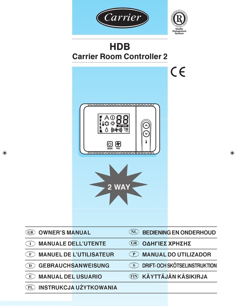
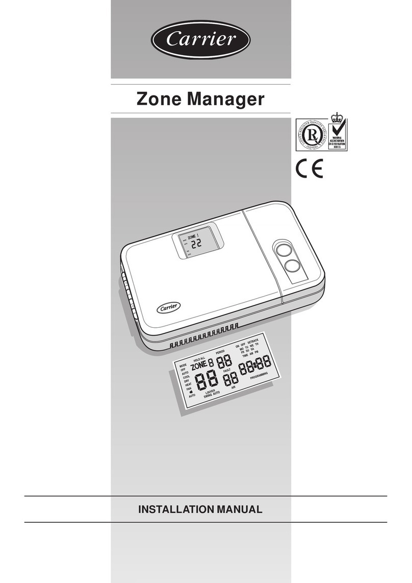
Carrier HDB User manual

HDB
Carrier Room Controller 2
2 WAY
INSTALLATION MANUAL MONTAGE-INSTRUCTIES
MANUALE DI INSTALLAZIONE OK
MANUEL D’INSTALLATION MANUAL DE INSTALAÇÃO
INSTALLATIONSANWEISUNG INSTALLATIONSMANUAL
MANUAL DE INSTALACIÓN ASENNUSOHJE

ENGLISH
Installation Manual
ITALIANO
Manuale di installazione
FRANÇAIS
Manuel d’installation
DEUTSCH
Installationsanweisung
ESPAÑOL
Manual de instalación
NEDERLANDS
Montage-instructies
K
OK
PORTUGUÊS
Manual de instalação
SVENSKA
Installationsmanual
SUOMI
Asennusohje
HDB - Carrier Room Controller 2

HDB - Carrier Room Controller 2
GB - 1
Installation manual
ENGLISH
This control system only operates with all hydronic indoor units.
Contents
Page
Aspect and display .................................................................................................... 2
General information ................................................................................................. 3
Choosing the installation site .................................................................................... 3
Installation................................................................................................................. 4
Electrical connections .............................................................................................. 5
Room controller 2 configuration ................................................................................. 5/6
Troubleshooting......................................................................................................... 6
108
70
20
INSTALLATION FLOW CHART
Read manual
Install
Room Controller2
Wire Room Controller 2
and unit network
Configure
Room Controller 2
Test System
Operate
Room Controller 2.
Start installation test.
Dimension (mm)

GB - 2
HDB - Carrier Room Controller 2
Aspect and display
Off
Desired temperature / room temperature
Set-point setting indicator
Louver position
Fan speed
Bar-graph (appears at power-up only)
Automatic mode
Operating mode (Cooling and Heating)
Dry mode
A= Display
C = Key for selecting the operating mode
D= Key for increasing temperature/changing louver setting
E= Button for selecting the fan speed/ louver mode selection
F= Key for decreasing temperature/changing louver setting
S= Room temperature sensor
V= Back panel fixing screws
A D
E S
F
V
C
V

GB - 3
HDB - Carrier Room Controller 2
ENGLISH
The Room Controller 2 Location
The CRC2 can be installed on a unit only if this unit is the
Fancoil Cabinet.
For wall-mounting, follow the instructions below:
If fitted to a wall, the Room Controller must be mounted:
•Inthesameareawheretheunitislocated,preferablyonan
inside partitioning wall.
•Approximately1.5mfromoor.
•Onasectionofwallwithoutpipesorductwork
General information
IMPORTANT:
Read the entire instruction manual before starting the
installation.
• Fortrouble-freeinstallation,whichshouldbecarriedoutbya
qualified installer, follow the installation chart sequence.
• Followallcurrentnationalsafetycoderequirements.
In particular ensure that a properly sized and connected
ground wire is in place.
• Afterinstallationthoroughlytestthesystemoperationand
explain all system functions to the owner.
• Leavethismanualwiththeownerforconsultationduringfuture
periodic maintenance.
• Disposeofpackagingmaterialinaccordancewithlocal
requirements.
• Themanufacturerdeniesanyresponsibilityandwarrantyshall
be void if these installation instructions are not observed.
• Inspectequipmentfordamageduetoimpropertransportation
or handling: file an immediate claim with the shipping company.
Do not install or use damaged units.
• Incaseofanymalfunctioningturntheunitoff,disconnectthe
mains power supply and contact a qualified service engineer.
Room Controller 2: Hydronic Fancoil Solutions
Power
Note that the Room Controller 2 requires no batteries and is not
“power stealing”. It requires 12 VDC to be connected for proper
operation, which is easily obtained from the Unit connected to it.
The Room Controller 2 will not operate without this connection.
If the indoor air sensor on the Room Controller has been
selected, it should NOT be mounted:
•Closetoawindow,onanoutsidewall,ornexttoadoorleadingto
the outside.
•Exposedtodirectlightandheatfromalamp,sun,replace,or
other temperature-radiating object which may cause a false
reading.
•Closetoorindirectairowofaheatingorcoolingsupply.
•Inareaswithpooraircirculation,suchasbehindadoororinan
alcove.
• Maximumcablelength:150m
Choosing the installation site and installation
Minimum clearances

GB - 4
HDB - Carrier Room Controller 2
•Matchandconnectequipmentwirestoproperterminalsinthe
connector block.
Both power and communication wires must be connected
correctly for proper Room Controller operation.
•Pushanyexcesswireintothewallandagainstmountingbase.
If the air sensor is being used on the Room Controller 2, seal
hole in wall to prevent air leaks.
Leaks can affect sensor operation.
•PushtheRoomController2snaphingetothebase.
Mounting
WARNING:
Before installing the Room Controller 2, turn off all power
to the Unit that will supply power to the Room Controller 2.
Electrical shock can cause personal injury or death.
It is not possible to connect more than one user’s interface to
each single machine. For the correct operation of Room Con-
troller 2 disconnect the LED card if fitted.
•TurnOFFallpowertounit.
•OpentheRoomController2rearmountingbasetoexpose
mounting holes.
The base can be removed to simplify mounting (snap apart
carefully at hinge to separate mounting base from remainder of
the Room Controller 2).
•RoutetheRoomController2wiresthroughthelargeholein
the mounting base.
Level mounting base against wall (for aesthetic value only the
Room Controller 2 need not be level for proper operation) and
mark the wall through the 2 mounting holes.
•Drilltwo5mmmountingholesinwallwheremarked.
•Securemountingbasecorrectly( ) to wall with 2 screws
and anchors provided, (additional anchoring holes available for
more secure mounting if needed) making sure all wires extend
through hole in mounting base.
•Adjustlengthandroutingofeachwiretoreachtheproper
terminal in the connector block on the mounting base, with
6 mm of extra wire (strip only 6 mm of insulation from each
wire to prevent adjacent wires from shorting together when
connected).
Installation
Mountingscrews
To indoor unit
Rigid PVC conduit
inside
ø 30mm min.
Plaster approx
30 mm
Room Controller 2
Connector block
Connection cable
Connection cable
G
P
C
I
G
P
C
I
I
G
P
C
I

GB - 5
HDB - Carrier Room Controller 2
ENGLISH
•TurningtheCRC2controloff
•KeeptheMODEbuttonpressedforatleast5secondstoenter
the configuration menu.
“10" is displayed on the screen, which represents the first item
that can be displayed and configured.
•Tocheckthe10itemvalue,presstheMODEbutton.
Connection of Room Controller 2 to HDB control
panel box
WARNING: Before connecting any wiring to the Room
Controller 2, turn off all power to the unit that will supply
power to the Room Controller, 2.
Electrical shock can cause personal injury or death.
Wiring Materials required
(supplied by installer)
• 1smallscrewdriver
• 4x0,5mm2multiple cables, double insulated.
Suggested type: H03VV-F.
Keep it pressed for
at least 5 seconds Check the
value Change the
value
up
down
up
down
To check/change the
values of items 11,
12 and 13 go back to
point A
A
Store by pres-
singMODE
•PressMODEbuttontodisplaythevalueandchangeitby
pressing UP or DOWN keys. Do the same for the other items.
•Toconrmachangedvalue,pressMODEbuttonorthechange
will not be stored.
I
321
CGPI
C
P
G
Electrical connections and Room Controller 2 configuration
Control and System Configuration
Press UP and DOWN keys to change the value. Press the
MODEbuttontoconrmtheselectedvalue.
Now 10 appears again on the display.
•Todisplayorchangethefollowingitems,pressUPorDOWN
keys until the desired item is displayed.
•ToexitfromthemenupressFANbuttonorwait10secondswi-
thout pressing any button.
•Thecongurablevaluesareshowninthetable.
All values set by the manufacturer are underlined in the
“Values” column.
Configuration
Item Value Description
10 H
G
Remote Heating/Cooling
Remote cooling only
11 On
OFF
Room Thermistor Override Active
Control and display room air temperature at the 2 WAY CRC control
Room Thermistor Override Inactive
Display the controlling room air temperatureat the 2 WAY CRC from the FCU
12 °C
°F Temperatures displayed in degrees C
Temperatures displayed in degrees F
13 10 – 50 : 10° - 50°C
50 – 122 : 50° - 122°F Maximumsetpointinheatingmode(indegreesCorFdependingonconguration12)
Default value: 32°C or 90°F
14 10 – 50 : 10° - 50°C
50 – 122: 50° - 122°F Minimumsetpointincoolingmode(indegreesCorFdependingonconguration12)
Default value: 17°C or 63°F
Configuration table for HDB units

GB - 6
HDB - Carrier Room Controller 2
Room Controller 2 configuration, troubleshooting
Item #Value Descrizione
Cold draft thermistor 20 1
0Cold Draft thermistor installed
Cold Draft thermistor not installed
CCN address 21 1 – 199 CCN address
Electric Heaters Option 22
0
1
2
3 – 199
Not installed
Low power without “booster heating”
Low power with “booster heating”
High power
Dead band 23 1
2 – 6
6
The unit uses only the values from 2 to 6
From 2 to 6
> 6 is equal to 6
Off / ECO 24 0
1
Turning the unit OFF, only the antifreeze protection is active
Turning the unit OFF, ECO mode is active.
The units are configured at the factory. In the case of check or
change, the installer should follow the instructions below:
. Check all the electric connections (instructions and wiring
diagrams).
. Turning the CRC control off, keep the UP and DOWN buttons
simultaneously pressed for more than 5 seconds.
. After 5 seconds, the code “20” is displayed.
.PresstheMODEbuttontocheckorchangetheset-upvalue
using UP and DOWN buttons.
. Press FAN button to send the unit the new configuration;
reception of the new vales will be confirmed by the unit.
.PressMODEtoscrollalltheitemsavailableasshowninthetable
below.
Note:
When 30 seconds have elapsed and no buttons have been
pressed, the control will automatically exit the configuration
mode and the procedure has to be restarted.
Symptom Possible Cause Things to check Solution
No LCD display
1) mis-wiring of the 12 volt
power to Room Controller 2 control. 1) Verify that +12V and Ground are con-
nected to the proper terrminals of the
Controller. Reference Installation wir-
ing section for correct connections
After disconnecting the power, correct the
wiring problem and re-cycle power.
2) Power not online 1) Check that the units main power is
connected.
The main control board should be
operating normally
After verifing the wiring to the Room
Controller 2, re-cycle the unit power.
3) No 12 volts between P and G of
terminal block. 1) Check the installation of the J6 plug
on the main control board. After disconnecting the power, correct
the wiring problem and re-cycle power.
+12 volts applied to Room Control-
ler at the correct terminals and still
does not operate
1) The Room Controller 2
is damaged. Change the Room Controller 2 and
re-cycle power.
The data sent by the indoor unit are
not displayed. 1) The connecting cable between the
unit to the Room Controller2 is cut or
not properly connected.
1) Check connection to J2 on the unit
and on CRC2 “I” connector. After disconnecting the power, correct
the wiring problem and re-cycle power.
Icon A is displayed.There is no
active button 1) Interference from another interface
on the CRC2 communication line. 1) Check that the LED card is con-
nected. Disconnect the LED card.
For Cassette units this should be made
by disconnecting the black connector
under the grille filter.
The following fault codes will be displayed next to temperature:
Code Description
A1 Air temperature sensor alarm
A2 Communication lost with terminal
A3 Terminal alarm
A1: This alarm starts if the sensor detects a temperature lower
than -17°C or higher than 63°C for more than 15 seconds. The
alarm stops when the temperature value returns and remains
within the limits for more than 15 seconds.
A2: This alarm starts if the control does not communicate with the
terminal for 5 consecutive messages. The control works even
in case of fault and the alarm stops as soon as it receives the
answer from the terminal.
A3: This alarm starts every time the terminal sends an alarm
message to the control (for more details on the alarms, refer to
Control instructions on the machine). The control works even in
case of fault and the alarm stops as soon as the cause for the
Terminal alarm is detected and repaired.
Troubleshooting

HDB - Carrier Room Controller 2
I - 1
Manuale di installazione
ITALIANO
108
70
20
Dimensioni (mm)
Questo sistema di controllo funziona con tutte le unità interne idroniche.
Indice
Pagina
Aspetto e display ....................................................................................................... 2
Informazioni generali ................................................................................................ 3
Scelta del luogo di installazione ................................................................................. 3
Installazione.............................................................................................................. 4
Collegamenti elettrici................................................................................................. 5
Configurazione Room Controller 2............................................................................. 5/6
Problemi e soluzioni .................................................................................................. 6
SCHEMA DI INSTALLAZIONE
Lettura del manuale
Installazione
Room Controller 2
Collegamento in rete
del RC con le unità
Configurazione
del Room Controller 2
Verifica Sistema
Messa in funzione
del Room Controller 2.
Avviare il Test d'installazione.

I - 2
HDB - Carrier Room Controller 2
Aspetto e display
Spento
Temperatura desiderata/temperatura ambiente
Indicatore impostazione set-point
Posizione louver
Velocità ventilatore
Bar-graph (visibile alla sola accensione)
Modo automatico
Modalità di funzionamento
(Raffrescamento e Riscaldamento)
Modo Deumidificazione
A= Display
C = Selezione della modalità di funzionamento
D= Incrementare la temperatura/modifica
impostazioni louver
E= Selezione velocità ventilatore/selezione modalità louver
F= Decrementare la temperatura/ modifica impostazione
louver
S= Sensore di temperatura ambiente
V= Viti fissaggio pannello posteriore
A D
E S
F
V
C
V

I - 3
HDB - Carrier Room Controller 2
ITALIANO
Collocazione del Room Controller 2
Il CRC2 può essere installato a bordo macchina solo
sul ventilconvettore a mobiletto.
Altrimenti montare a muro seguendo le indicazioni successive:
In caso di applicazione a parete, il Room Controller 2 deve
essere montato:
• Nellastessazonaincuisitroval’unitàadessocollegata,
preferibilmente su una parete divisoria interna.
• Approssimativamentea1,5mdaterra.
• Inunazonadellaparetechenonsiaattraversatadatubio
condutture.
Informazioni generali
Room Controller 2 : Soluzioni con ventilconvettori idronic
Se è stato selezionato il sensore dell'aria interno, il Room
Controller NON deve essere montato:
•Vicinoadunanestra,suunmuroesternoovicinoaduna
porta che conduce fuori.
•Espostoallalucedirettadelsoleoalcaloreprovenientidauna
lampada, vicino ad un camino o ad altri oggetti che emanano
calore perché ciò' potrebbe causare un funzionamento non
corretto.
• Vicinoacorrentidiretted'ariacaldaofredda.
• Inzoneconpocacircolazioned'aria,comedietroadunaportao
in ambienti molto piccoli e chiusi.
• Massimalunghezzadeicavi:150m.
Scelta del luogo d'installazione ed installazione
Spazio minimo
IMPORTANTE:
Leggere attentamente questo manuale prima di iniziare
l’installazione.
•L’installazionedeveessereeseguitadapersonalespecializzato
rispettando la sequenza di operazioni indicata nello schema
d’installazione.
•Eseguirel’installazionerispettandolenormativedisicurezza
Nazionaliinvigore.Inparticolareassicurarsichesia
disponibileun’efcacelineadimessaaterra.
•Dopol’installazioneeseguireilcollaudofunzionaleedistruire
l’utentesulcorrettofunzionamentodelclimatizzatore.
•Lasciareilpresentemanualeall’utenteinmodoche
possa essere consultato per le periodiche operazioni di
manutenzione.
•Eliminareilmaterialediimballaggiorispettandolevigenti
normative.
•Ilproduttoreriutaqualsiasiresponsabilitàelagaranzia
sarà nulla se non verranno osservate queste istruzioni di
installazione.
•Assicurarsichel’unitànonabbiasubitodannidurante
il trasporto; nel caso esporre immediato reclamo allo
spedizioniere.
Noninstallareneutilizzareapparecchidanneggiati.
•Incasodifunzionamentoanomalospegnerel’unità,togliere
l’alimentazioneelettricaerivolgersiapersonalespecializzato.
Alimentazione
Il Room Controller 2 non necessita di batterie per il funzionamento
corretto esso ha bisogno di 12 VDC e cioè facilmente ottenibile da
qualsiasi unità ad esso collegata.
Il Room Controller 2 non funzionerà senza questo collegamento.

I - 4
HDB - Carrier Room Controller 2
Viti fissaggio
Cavetto di collegamento
G
P
C
I
G
P
C
I
I
G
P
C
I
•Collegareicaviairelativiterminalisullamorsettiera.
I cavi di alimentazione e quelli di comunicazione devono
essere collegati correttamente per un buon funzionamento del
Room Controller 2.
•Spingereicaviineccessonelmuroecontrolabasedi
montaggio. Se viene utilizzato il sensore dell'aria sul Room
Controller 2, sigillare il foro nel muro per evitare l'ingresso di
aria attraverso il muro che potrebbe influire negativamente sul
funzionamento del sensore.
•RicollegarelabasedelRoomController2alsuocardine.
Montaggio
ATTENZIONE:
Prima di installare il Room Controller 2, togliere
l'alimentazione elettrica verso l'unità che alimenterà il Room
Controller 2. Le scosse elettriche possono causare ferite e
danni molto gravi alle persone.
Non è possibile collegare più di un'interfaccia utente ad una
singola macchina. Per il corretto funzionamento del Room
Controller 2 scollegare l'eventuale scheda LED.
•Toglierel'alimentazioneelettricadell'unità.
•AprirelabaseposterioredelRoomController2(basedi
montaggio) per accedere ai fori di fissaggio alla parete.
La base può essere rimossa dai cardini per semplificare le
operazioni di montaggio (effettuare con cautela l'operazione
di distacco dal cardine per separare la base di montaggio dal
resto del Room Controller 2).
•InserireicavidelRoomController2attraversoilforogrande
nella base di montaggio. Livellare la base di montaggio contro
la parete (soltanto ai fini estetici).
Il Room Controller 2 non ha bisogno di essere a livello per
poter funzionare) e fare dei segni sul muro in corrispondenza
dei 2 fori di montaggio.
•Praticaredueforisullapareteda5mmincorrispondenzadei
due segni.
•Fissarelabase( ) alla parete con 2 viti e i tasselli in
dotazione (se necessario, fori di ancoraggio aggiuntivi sono
disponibili per un montaggio più sicuro) assicurandosi che tutti
i cavi siano ben tesi attraverso il foro della base.
•Regolarelalunghezzaedilpercorsodiognicavoversoil
giusto terminale della morsettiera collocata sulla base di
montaggio. Tenere 6 mm di cavo in più.
(Spellare 6 mm di guaina da ogni cavo per evitare che i cavi
adiacenti provochino un cortocircuito quando collegati).
Installazione
All'unità interna
Condotto rigido
in PVC
ø 30 mm min.
Intonaco 30 mm
circa
Room
Controller 2
Scatola di
derivazione

I - 5
HDB - Carrier Room Controller 2
ITALIANO
• SpegnereilcomandoCRC2.
• Perentrarenelmenùdicongurazione,tenerepremutoil
pulsanteMODEperalmeno5secondiconsecutiviconil
comando CRC2 spento. Sullo schermo verrà visualizzato “10” che
rappresenta la prima voce visualizzabile e configurabile.
Collegamento del Room Controller 2 al quadro
elettrico HDB
ATTENZIONE:
Prima di effettuare qualsiasi collegamento spegnere
l'alimentazione dell'unità che alimenterà il Room Controller.
Le scosse elettriche possono causare ferite o gravi danni
alle persone.
Materiali di cablaggio necessari
(a cura dell’installatore)
• 1cacciavitepiccolo
• Cavimultipli4x0,5mm2, a doppio isolamento.
Tipoconsigliato:H03VV-F.
tenere premuto per
almeno 5 secondi controllare
il valore cambiare
il valore
up
down
up
down
per controllare /cambiare
i valori delle voci successive
(11,12,13...), ripartire dal
punto A
A
memorizzare
premendo
MODE
• PremereMODEpervisualizzareilvaloreemodicarloconUP
oDOWN.Procederenellostessomodoperlevocirestanti.
• Perconfermarelamodicaeseguitasuunvalore,premere
sempreilpulsanteMODE,altrimentiilcambiamentoverràperso.
I
321
CGPI
C
P
G
Collegamenti elettrici e configurazione Room Controller 2
Configurazione del comando e del sistema
• Percontrollareilvaloredellavoce10,premereMODE.Per
modicareilvalorepremereilpulsanteUPoDOWN.Premere
ilpulsanteMODEperconfermarelaselezione.Oraildisplay
tornerà a visualizzare la voce 10.
• Pervisualizzareemodicarelevocisuccessive,premereUPo
DOWNnoallavocedesiderata.
• PerusciredalmenupremereilpulsanteFANoattendere10
secondi senza premere alcun pulsante.
• Ivaloricongurabilisonoriportatiintabella.TuttiIvaloriimpostati
dafabbrica,sonosottolineatiall’internodellacolonna“Valori”.
Item Valore Descrizione
10 H
G
Riscaldamento/Raffreddamento remoto
Solo raffreddamento remoto
11 On
OFF
Termistore Override Ambiente Attivo
Controlloevisualizzazionedellatemperaturadell’ariaambientesucomandoCRCa2VIE
Termistore Override Ambiente Non attivo
Visualizzazionedellatemperaturadell’ariaambientesucomandoCRCà2VIEdallaFCU
12 °C
°F Temperatura visualizzata in gradi C
TemperaturavisualizzataingradiF
13 10 – 50 : 10° - 50°C
50–122:50°-122°F
Ilmassimosetpointdiriscaldamento(inGradiCoFèdeterminatodallacongurazione12)
Valoredidefault:32°Cor90°F
14 10 – 50 : 10° - 50°C
50–122:50°-122°F
Ilminimosetpointdiraffrescamento(inGradiCoFèdeterminatodallacongurazione12)
Valoredidefault:17°Cor63°F
Tabella di configurazione per le unità HDB

I - 6
HDB - Carrier Room Controller 2
Configurazione Room Controller 2, problemi e soluzioni
Item #Valore Descrizione
Sensore Cold draft 20 1
0Sensore di Cold Draft installato
Sensore di Cold Draft non installato
CCN Indirizzo 21 1 – 199 CCNIndirizzo
Opzioni Resistenze Elettriche 22
0
1
2
3 – 199
non installate
Bassa potenza senza booster heating
Bassa potenza con booster heating
Alta potenza
Dead band 23 1
2 – 6
6
L’unitàusasoloIvalorida2a6
Da 2 a 6
> 6 é uguale a 6
Off / ECO 24 0
1
Conl’Unitàspentasaràattivosolol’antifreezeprotection.
Spegnendol’unitàsaràattiol’ECO
Le unità vengono pre-configurate in fabbrica.
Nelcasodivericaomodicadapartedell’installatore,seguirele
seguenti istruzioni:
• VericaretuttiIcollegamentielettrici(istruzionieschemi).
• ConilCRCspento,tenerepremuticontemporaneamentei
pulsantiUPeDOWNperpiùdi5secondi
• Dopo5secondiappariràilcodice“20”suldisplay.
• PremereilpulsanteMODEpervericareocambiareilvaloredi
questoset-upconipulsantiUPeDOWN.
• PremereilpulsanteFANpertrasmettereall’unitàlanuova
congurazione,l’unitàconfermeràl’avvenutaricezionedeinuovi
valori.
• PremereMODEperscorreretuttigliitemsdisponibilecomeda
tabella sotto riportata.
Nota:
Trascorsi 30 secondi senza che alcun tasto sia stato
premuto, il comando esce automaticamente dalla modalità di
configurazione e la procedura dovrà essere ripetuta dall’inizio.
Sintomo Possibile Causa Controlllo da effettuare Soluzione
Nonfunzionaildisplay
1) Collegamento errato dei cavi di
alimentazione (12V) al Room
Controller 2
1)Verificare che i collegamenti al +12V
e al GND siano corretti sia sul Room
Controller 2 che sulla morsettiera
dell'unità.Fareriferimentoallasezione
riguardante l'installazione dei cablaggi.
Dopoavertoltol’alimentazione,
correggere il problema sul cablaggio e
riattivarel’alimentazione.
2) Manca l'alimentazione 1)Controllarechecisial’alimentazione
principale nelle unità. La scheda
elettronica principale dovrebbe
funzionare normalmente.
Dopo aver verificato il cablaggio
verso il Room Controller, riattivare
l’alimentazione.
3)Mancal’alimentazionea12Volttra
P e G della morsettiera. 1) Controllare il collegamento del
connettore J6 sulla scheda principale Dopoaverscollegatol’alimentazione,
correggere il problema sul cablaggio e
riattivarel’alimentazione.
L'unità non funziona anche se i
cavi di alimentazione sono collegati
correttamente (+12 volt)
1) Il Room Controller 2 è danneggiato. Cambiare la centralina Room Controller
2eriattivarel’alimentazione.
Il display non si aggiorna con i dati
inviatolidall’unitàinterna 1)Ilcavodicollegamentodall’unitàal
Room Controller2 è interrotto o mal
collegato.
1) Verificare la connessione su J2
dell’unitàesulCRC2connettore“I” Dopoavertoltol’alimentazione,
correggere il problema sul cablaggio e
riattivarel’alimentazione
Ildisplayvisualizzal'iconaA.Nessun
pulsante è operativo 1)Un'altrainterfacciadisturbalalinea
di comunicazione del CRC2 1)VericareselaschedinaLEDè
collegata ScollegarelaschedinaLED.Perl'unità
Cassette, effettuare l'operazione
scollegando il connettore nero sotto il
filtro della griglia.
Di seguito vengono riportati I codici di errore che compariranno sul
Display in corrispondenza della temperatura:
Codice Descrizione
A1 Allarme del sensore temperatura aria
A2 Perdita della comunicazione con il terminale
A3 Terminale in allarme
A1: Questo allarme interviene in caso la sonda segnali una
temperatura inferiore a -17°C o maggiore di 63°C per un
periodo superiore a 15 secondi.
L’allarmeverràripristinatodopocheilvaloreditemperatura
sarà rientrato nei limiti per un periodo superiore a 15 secondi.
A2: Questo allarme si attiva nel caso in cui il controllo non riesca
a comunicare con il terminale per 5 messagi consecutivi. Il
Controllorimaneoperativoancheincasodierroreel’allarme
verrà ripristinato non appena riceverà un messaggio di risposta
dal terminale.
A3: Questo allarme è attivo ogniqualvolta il terminale comunica
al Controllo un segnale di allarme (consultare le istruzioni
del Controllo a bordo macchina per il dettaglio degli allarmi).
Il controllo rimane operativo anche in caso di errore e verrà
ripristinatononappenalacausadell’allarmedelTerminalesarà
soluzionata.
Diagnostica

HDB - Carrier Room Controller 2
F - 1
Manuel d'installation
FRANÇAIS
108
70
20
Dimension (mm)
Ce dispositif de contrôle fonctionne uniquement avec toutes les unités intérieures hydrauliques.
Table des Matières Page
Aspect et affichage.................................................................................................... 2
Informations générales ............................................................................................. 3
Choix du site d’installation ......................................................................................... 3
Installation................................................................................................................. 4
Les branchements électriques .................................................................................. 5
Configuration du Room Controller 2........................................................................... 5/6
Dépistage des problèmes de fonctionnement............................................................. 6
SÉQUENCE DES OPÉRATIONS D’INSTALLATION
Lire le manuel
Installer le
Room Controller 2
Effectuer le câblage entre le
RC et le réseau d’appareils
Programmer le
Room Controller 2
Tester le dispositif
Mettre le Room
Controller 2 en service.
Démarrer l’Essai d’installation.

F - 2
HDB - Carrier Room Controller 2
Aspect et affichage
Eteint
Température souhaitée / Température ambiante
Indicateur de configuration du point de consigne
Position louver
Vitesse ventilateur
Bargraph (s’affiche uniquement lors de l’allumage)
Mode automatique
Modalité de fonctionnement (Refroidissement et Chauffage)
Mode Déshumidification
A= Affichage
C = Touche pour la sélection de la modalité de fonctionnement
D= Augmenter la température / modifier paramétrage louver
E= Touche pour la sélection de la vitesse de ventilation /
sélection mode ailette (louver)
F= Diminuer la température / modifier paramétrage louver
S= Capteur de température ambiante
V= Vis de fixation du panneau arrière
A D
E S
F
V
C
V

F - 3
HDB - Carrier Room Controller 2
FRANÇAIS
Emplacement du Room Controller 2
Le CRC2 peut être installé sur une unité uniquement s’il s’agit
de l’unité ventilo-convecteur carrossé.
Si celle-ci n’est pas disponible, procéder à l’installation au mur en
suivant les instructions ci-dessous :
En cas d’application au mur, le Room Controller 2 doit être
monté:
•Danslamêmezoneoùsetrouvel’unité,depréférencesurun
mur intérieur.
•Àenviron 1,5 m du sol.
•Sur une portion de mur ne contenant pas de tuyauteries ou de
conduites.
Informations générales
Si la sonde d’air interne sur le Room Controller 2 a été
sélectionnée, le dispositif ne devra PAS être monté:
•Prèsd’unefenêtre,surunmurextérieur,ouprèsd’uneporte
menant à l’extérieur.
•Exposédirectementàlalumièredusoleilouàlachaleurd’une
lampe, du soleil, d’une cheminée ou autre appareil irradiant de
la chaleur, car cela pourrait occasionner des erreurs de lecture.
•À proximité ou directement soumis à un flux d’air ou
dans le rayon d’action d’un appareil de chauffage ou de
conditionnement d’air.
•Dansdesendroitspeuaérés,commeparexemplederrièreune
porte ou dans un renfoncement.
•Longueurmaximaleducâble:150m.
Choix du site d'installation
Espaces libres minimum
IMPORTANT:
Lire attentivement ce manuel d’instructions
avant de commencer la mise en place de l’appareil.
• Pouruneinstallationsansproblème,ilestimportantdelafaire
exécuter par un installateur spécialisé et de suivre la séquence
d’opérations indiquée ci-contre.
• Respecterlesprescriptionsdesnormesnationalesenvigueur
en matière de sécurité, et notamment prévoir une connexion
de mise à la terre de dimensions convenables.
• Aprèsl‘installation,effectuerunessaicompletdusystèmeet
expliquer toutes les fonctions du système à l’utilisateur.
• Remettrecemanuelàl’utilisateurpoursaconsultationà
l’occasion de futures opérations d’entretien.
• Eliminerlematérield’emballagedanslerespectdes
règlements locaux.
• Lefabricantdéclinetoutesresponsabilitésetrécuse
toute garantie en cas de non-observation des instructions
d’installation.
• Inspecterl’appareilàsonarrivéeandedépisterles
dommages éventuels causés par le transport ou par une
manipulation incorrecte; dans ce cas, adresser immédiatement
une réclamation à la compagnie de transport.
• Encasdedysfonctionnement,éteindrel’appareil,le
débrancher de toutes les sources d’énergie et s’adresser à un
technicien de réparation spécialisé.
Room Controller 2 : Solutions de ventilo-convecteurs
hydrauliques
Alimentation électrique
Le Room Controller 2 n’a pas besoin de batteries et ne demande
pas un apport d’énergie important.
Pour fonctionner correctement, il doit être alimenté à 12VDC;
cette tension peut être facilement prise d’une des unités.
Sans cela, le Room Controller 2 ne pourra pas fonctionner.

F - 4
HDB - Carrier Room Controller 2
•Connecterlescâblesaveclabornecorrespondantesurla
barrette de raccordement et les connecter. Il est nécessaire
que les câbles d’alimentation et de communication soient
branchés correctement pour que le Room Controller 2
fonctionne.
•Pousserlesurplusdecâbleéventuelverslemuretcontrele
support de montage.Si la sonde d’air va être utilisée sur le
Room Controller 2, étancher le trou du mur afin d’empêcher les
fuites d’air qui pourraient compromettre le fonctionnement de
la sonde.
•EnclencherlacharnièreaveclabaseduRoomController2.
Montage
AVERTISSEMENT:
Avant d’installer le Room Controller 2, déconnecter toutes
les sources d’énergie de l’unité destinée à alimenter en
énergie le Room Controller 2. Une décharge électrique
pourrait provoquer des blessures graves ou la mort.
Il n’est possible de connecter plus d’une interface utilisateur à
chaque unité.
Afin d’assurer le correct fonctionnement du Room Controller 2
déconnecter la carte des diodes éventuellement installée.
•Mettrel’unitéhorstension.
•Ouvrirlabasepostérieuredemontagepouraccéderauxtrous
de fixation.
Pour simplifier l’assemblage, la base peut être enlevée
(déboîter doucement la charnière pour séparer le support de
montage du corps du Room Controller 2).
•Faire passer les câbles du Room Controller 2 à travers le grand
orifice de la base de montage.
Poser le support à plat contre le mur (uniquement pour des
raisons esthétiques, le Room Controller 2 n’a pas besoin d’être
nivelé pour fonctionner correctement) et faire des marques sur
le mur à travers les 2 trous de montage.
•Percer deux trous de 5 mm aux endroits marqués.
•Fixerlesupportdemontage( ) au mur à l’aide des 2 vis et
des plaques d’ancrage fournies (possibilité de pratiquer des
trous d’ancrage supplémentaires en cas de besoin pour un
montage plus sûr) et s’assurer que tous les câbles sont enfilés
dans le trou du support de montage.
•Réglerlapositionetleparcoursdechaquecâbledefaçon
à ce qu’il atteigne la borne correspondante sur la barrette
de raccordement située sur le support, en ne découvrant
que 6 mm de fil (n’enlever que 6 mm de gaine isolante afin
d’empêcher que les fils ne puissent se court-circuiter lorsqu’ils
seront branchés).
Installation
Vis de montage
Câbles de connexion
Câbles de connexion
G
P
C
I
G
P
C
I
I
G
P
C
I
Vers l' unité intérieure
Conduit rigide en PVC
et intérieur
30 mm min.
Plâtre à environ 30 mm
Room Controller 2
Bloc connecteur

F - 5
HDB - Carrier Room Controller 2
FRANÇAIS
•EteindrelacommandeCRC2.
•Pouraccéderaumenudeconguration,maintenirpressé
leboutonMODEpendantaumoins5secondes,avecla
commande CRC2 éteinte.
L’article «10», qui représente le premier article affichable et
configurable, sera affiché.
Câblage du Room Controller 2 au panneau
électrique HDB.
AVERTISSEMENT: Avant de brancher le Room Controller,
déconnecter toutes les sources d’énergie de l’unité destinée
à alimenter en énergie le Room Controller.
Une décharge électrique pourrait provoquer des blessures
graves ou la mort.
Matériel de câblage nécessaire
(fourni par l’installateur)
• 1petittournevis
• 4x0,5mm2câbles multiples à double isolation.
Type recommandé: H03VV-F.
Laisser pressé
pendant au moins 5
secondes
Contrôler la
valeur Changer
la valeur
up
down
up
down
Pour contrôler /
changer les valeurs
des articles suivants
(11,12,13...) répéter
les opérations à partir
du point A.
A
Mémoriser en
appuyant sur
MODE
•AppuyersurMODEpourafcherlavaleuretlachangeràl’aide
destouchesUPouDOWN.
Répéter cette opération pour les autres articles.
•Validerlechangementdevaleurenappuyantsurlebouton
MODE,autrementlavaleurneserapasmémorisée.
I
321
CGPI
C
P
G
Les branchements électriques et configuration du Room Controller 2
Configuration de la commande et du système
•Pourcontrôlerlavaleurdel’article10,appuyersurlebouton
MODE.AppuyersurlestouchesUPouDOWNpourchangerla
valeur.AppuyersurleboutonMODEpourvaliderlasélection.
L’article 10 apparaîtra de nouveau sur l’écran.
•Pourafcheroumodierlesarticlessuivants,appuyersurles
touchesUPouDOWNjusqu’àl’afchagedel’articlesouhaité.
•PoursortirdumenuappuyersurleboutonFANouattendre10
secondes sans appuyer sur aucun bouton.
•Lesvaleursparamétrablessontindiquéesdansletableau.
Les valeurs programmées à l’usine sont celles soulignées dans
la colonne « Valeurs ».
Article Valeur Description
10 H
G
Chauffage/Rafraîchissement à distance
Seul rafraîchissement à distance
11 On
OFF
Thermistor Override Ambiant Actif
Contrôleetafchagedelatempératuredel’airambiantsurlacommandeCRCà2VOIES
Thermistor Override Ambiant Inactif
Afchagedelatempératuredel’airambiantdecontrôlesurlacommandeCRCà2VOIESàpartirdelaFCU
12 °C
°F Températures affichées en degrés C
Températures affichées en degrés F
13 10 – 50 : 10° - 50°C
50 – 122 : 50° - 122°F Le point de consigne chauffage maximum (en Degrés C ou F est déterminé par la configuration 12 ci-dessus)
Valeur par défaut : 32°C ou 90°F
14 10 – 50 : 10° - 50°C
50 – 122 : 50° - 122°F Le point de consigne refroidissement minimum (en Degrés C ou F est déterminé par la configuration 12 ci-dessus)
Valeur par défaut : 17°C ou 63°F
Tableau de configuration pour les unités HDB

F - 6
HDB - Carrier Room Controller 2
Configuration du Room Controller 2, dépistage des problèmes de fonctionnement
Article # Valeur Description
Cold draft capteur 20 1
0Capteur cold draft installé
Capteur cold draft non installé
Adresse CCN 21 1 – 199 AdresseCCN
Options résistances électriques 22
0
1
2
3 – 199
non installé
Basse puissance sans accélérateur de chauffage
Basse puissance avec accélérateur de chauffage
haute puissance
Zone morte 23 1
2 – 6
6
L’unité utilise uniquement les valeurs de 2 à 6
De 2 à 6
> 6 est égal à 6
Off / ECO 24 0
1
En éteignant l’unité OFF,celle-ci est effectivement éteinte seule
protection antigel active
En éteignant l’unitéOFFlemodeECOestactif.
Les unités sont configurées à l’usine. En cas de contrôle ou de
changement par l’installateur, suivre les instructions :
• Contrôlertouslescâblagesélectriques(instructionsetschémas
de câblage)
• LeCRCéteint,appuyersimultanémentsurlesboutonsUPet
DOWNpendantplusde5secondes.
• Après5secondes,lecode«20»s’afchesurledisplay.
• AppuyersurMODEpourvérierouchangercettevaleurde
paramétrageàl’aidedesboutonsUPetDOWN.
• AppuyersurleboutonFANpourcommuniqueràl’unitéla
nouvelle configuration ; l’unité confirme la réception des nouvelles
valeurs.
• AppuyersurMODEpourfairedélertouslesarticlesdisponibles
comme indiqué dans le tableau ci-dessous.
Note:
Après 30 secondes sans qu’aucun bouton soit pressé, la
commande quitte automatiquement le mode de configuration
et la procédure devra être répétée dès le début.
Symptôme Cause possible Contrôles à effectuer Solution
L’écran LCD est absent
1) Erreur de câblage 12 volts
sur le contrôle du Room Controller 2 1)Vérifier que les connexions +12V
etGNDsontreliéesauxbornes
correspondantes du contrôle du Room
Controller 2.
Pour cela, consulter le chapitre
“Câblage”
Mettre l’appareil hors tension, corriger le
problème de câblage et remettre sous
tension.
2) Absence d’alimentation électrique
1) S’assurer que la source d’alimentation
principale des unités soit branchée.La
carte de commande principale devrait
fonctionner normalement.
Vérifier le câblage menant au contrôle
du Room Controller 2, puis remettre
l’unité sous tension.
3) Absence d’alimentation à 12 Volt
entre P et G du bornier. 1) Vérifier l’installation de la fiche J6 sur
la principale
Mettre l’appareil hors tension, puis
corriger le problème de câblage et
remettre sous tension.
La tension de +12 volts appliquée au
Room Controller 2 est correcte, mais ce
dernier ne fonctionne pas.
1) Le Room Controller 2 est endommagé Remplacer le dispositif de contrôle
du Room Controller 2 et rétablir
l’alimentation.
L’affichage ne s’actualise pas malgré
les données transmises par l’unité
intérieure.
1) Le câble de connexion de l’unité
au Room Controller2 est coupé ou
branchédefaçonincorrecte.
1) Vérifier la connexion sur le J2 de
l’unité et sur le CRC2 connecteur
« I ».
Après avoir coupé l’alimentation
secteur, éliminer le problème de
câblage et reconnecter l’alimentation
secteur.
L’icône A apparaît sur l’écran. Aucun
bouton n’est activé.
1) Une autre interface interfère avec la
ligne de communication du CRC2. 1) Vérifier si la carte des diodes est
connectée.
Déconnecter la carte des diodes. Pour
les unités Cassette, effectuer l’opération
en déconnectant le connecteur noir
situé sous le filtre de la grille.
Les codes d’erreurs suivants s’affichent sur le display à proximité
de la température:
Code Description
A1 Alarme sonde température de l’air
A2 Interruption de communication avec le terminal
A3 Alarme terminal
A1: Cette alarme s’active si la sonde détecte une température
inférieure à 17°C ou supérieure à 63°C pendant plus de
15 secondes. L’alarme est désactivée après que la valeur
de température est retournée dans les limites pendant une
période supérieure à 15 secondes.
A2: Cette alarme s’active si la commande ne communique pas
avec le terminal pour 5 messages consécutifs. La commande
est en fonction même en cas d’erreur et l’alarme est désactivée
dèsquelacommandereçoitunmessagederéponsedu
terminal.
A3: Cette alarme s’active chaque fois le terminal transmet un signal
d’alarme à la commande (pour plus d’info sur les alarmes,
se rapporter aux instructions de la Commande sur l’unité). La
commande est en fonction même en cas d’erreur et l’alarme
est désactivée dès que la cause de l’alarme du terminal est
détectée et réparée.
Au cas où
Other manuals for HDB
3
Table of contents
Languages:
Other Carrier Network Router manuals