manuals.online logo
Brands
  1. Home
  2. •
  3. Brands
  4. •
  5. Carrier
  6. •
  7. Thermostat
  8. •
  9. Carrier 33CS400-01 User manual

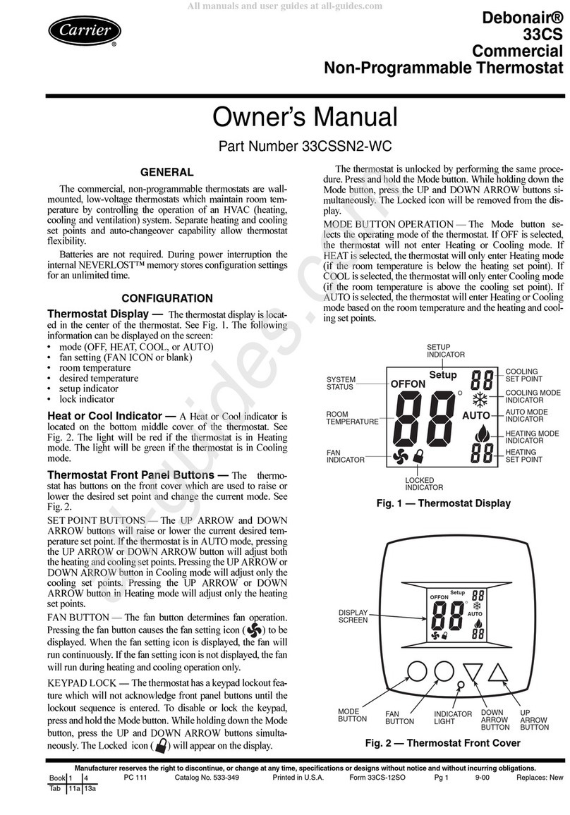
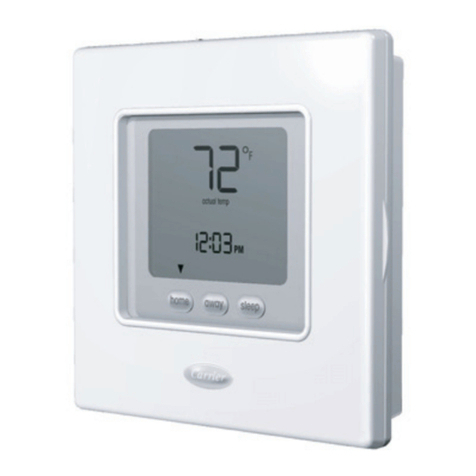
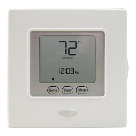
Carrier 33CS400-01 User manual

CAUTION
Follow the Installation Instructions before proceeding.
Set the thermostat mode to "OFF" prior to changing
settings in setup or restoring Factory Defaults.
CAUTION
NEVER PUTMORE THAN ONE
JUMPER ON THE SAME M]SC
JUMPER BLOCK!
THIS MAY DAMAGE YOUR
THERMOSTAT. Mis¢_
OK
NOTE: Due to variations in environmental conditions, it is not
always possible to achieve the desired humidification or
dehumidification setpoint.
This device complies with Part 15 of the FCC Rules. Operation is
subject to the following two conditions: (1) this device may not cause
harmful interference, and (2) this device must accept any interference
received, including interference that may cause undesired operation.
O Thermostat 3368400 01
CUS F_ Tested to Complywith FCC Standards
LISTED FORHOMEOROmCEUSE
4Z95
Pagei
The Table of ContenL_ divides the thermostat features into sections
making it easier to quickly find information.
The first page of each section contains a more detailed list of the
contents within that section, such as the example page shown below.
Header shows section #
Section 14 Contents: and title of section
mAdjusting the Heat!Cool
Differential ............................. 14.2
=Adjusting the Cycles ............
Per Hour. ................................. 14.3 .........J;_'"Section contents
mAdjusting the Deadband .......... 14.4 _JJ_......
mAdjusting the Minutes of
Run-Time Before the
Next Stage ............................... 14.6 _
=Selecting 2nd Stage Turn Visible section tab
Off Temperature ..................... 14.7 on the side of the
page
,_"'J" " ,,,,_Section and page #
Page 14.1
In addition, this manual also has an Index to help you find any information
regarding this thermostat quickly.
Page ii
Auto-Changeover: A mode in which the thermostat will turn on
the heating or cooling based on room temperature demand.
Configurable Output Jumper: Using jumpers on the thermostat
you can configure the MISC1, MISC2, and MISC3 terminals to
control humidification, dehumidification, and 2nd stage cooling.
Cool Setpoint: The warmest temperature that the space should
rise to before cooling is turned on (without regards to
deadband).
Deadband: The number of degrees the thermostat will wait, once
setpoint has been reached, before energizing heating or cooling.
Dehumidify: To reduce the amount of moisture in the air.
Differential: The forced temperature difference between the
heat setpoint and the cool setpoint.
Heat Setpoint: The coolest temperature that the space should
drop to before heating is turned on (without regards to
deadband).
Humidify: To increase the amount of moisture in the air.
Icon: The word or symbol that appears on the thermostat
display.
Mode: The current operating condition of the thermostat (i.e. Off,
Heat, Cool, Auto).
Non-Programmable Thermostat: A thermostat that does not
have the capability of running the Time Period Programming.
Temperature Swing: Same as Deadband.
Page iii
Page iv
Section 1 Contents:
=Selecting the Heat or Cool
Mode ............................................ 1.2
aSelecting Your Desired
Temperature ................................ 1.3
mUsing the Fan Button ................... 1.3
Note: Following the instructions in this section will allow you to
operate your thermostat using the factory default settings. These
settings are depicted in the illustrations throughout this manual.
P_el.i
Sdecting the Heat or Cool Mode
Select Mode by Pressing the MODE Button
Heating Only
The HEATsetting indicates the
temperature the room has to
reach before the furnace will
turn on to heat the room.
Cooling Only
The COOL setting indicates the
temperature the room has to
reach before the air conditioner
will turn on to cool the room,
Heating or Cooling
AUTO will automatically select
heat or cool based on room
temperature demand,
Off
OFF indicates both heating
and air conditioning
systems are turned off.
,"-_iS
O0
IO
COOL
"Tl_-
IO
'COOL
AUTO
HEAT
cO
Ou
Press
<Press
Press
Page 1.2
Selecting Your Desired 7_mperature
(adjusts- thes_oints)
AUTO MODE
Pressing the UP or DOWN buttons in Auto mode
will adjust both the heat and cool set temperatures
simultaneously. Adjust the desired
_'[C.] set temperature with the
I#=l I
: COOL
HEAT
BSj
buttons.
HEAT OR COOL MODE
Pressing the UP or DOWN buttons in Heat or Cool mode will
adjust only the heat or cool set temperature.
Adjust the desired
set temperature with the
buttons.
Press
Using the Fan Button F_ 0
_ Fan On indicates constant fan operation.
_1_1 If Fan On is selected the fan will run
coo continuously at all times, except in Off,
A o C °_ and will only run if there is a heating or
II_A cooling demand in Unoccupied periods.
FanOn _'_C_ Pressing the FAN button toggles this
feature on or off.
Page 1.3
Section 2 Contents:
=Front Panel Buttons ..................... 2.2
mDisplay Features ........................... 2.3
Page 2. I
Fwnt Panel
Backlit LCD Disptay (gIows red) to as the UP button
Heat or COOl Demand indicator Override
Red = Heat, Green = Cool Button
nE ,L/
QUICK RELEASE FOR
ACCESSORY PORT
(pg. ta.t}
MODE HUMIDITY FAN
Page 2.2
OUTSIDE °RESET
FILTER
Dis/#e, r tures
Service Filter
Pan UV Light
_ AUTO
OFFON
Override
FanOn
Setu ?
O Mode indicators Section 3
Selects the operational mode of the equipment.
HEAT _indicates the heating mode.
COOL - indicates the air conditioning mode.
AUTO - indicates the system will automatically changeover
between heat and cool modes as the temperature varies.
OFF - indicates heating and cooling is turned off.
O Room Temperature Disp{ay - Section 4
Indicates the current room temperature and displays the outside
temperature when selected.
I_ Desired Set Temperature - Section 3/4
indicates desired room temperature(s). Also displays the daily
maximum and minimum outside temperatures.
O Outside icon - Section 4
indicates the temperature displayed is from the optional outside
sensor.
_ Override icon - Section 5
indicates the Unoccupied mode of the thermostat is being overriden
for up to 4 hours. Page 2.3
DisplayFeatures
DeHumidif _
Service Filter
_ight
OFFON
Override
FanOn
Le
Remote
O Setup icon - Sections 6-15
Indicates the thermostat is in the setup mode.
O Fan On icon - Section 6
indicates constant, continuous fan operation. When Fan On is not
lit - indicates the fan will only operate when necessary to heat or to
cool.
I_ Service Filter icon - Section 15
Appears when the filter should be serviced under normal conditions.
Adjustable from 0 - 1950 hours of blower operation.
_ icon- Section 7
_tndicates keypad has been locked.
_)UV Light icon - Section 10/15
Appears when the UV bulb should be serviced under normal
conditions. Adjustable from 0 - 1950 days of operation.
_ Rernote icon - Pages4.2, 13.3 &17.3
Indicates the remote sensor reading of the thermostat is being
viewed.
Page 2.4
Display Features
Service Filter
Pan UV Light
AUTO
OFFON
Override
FanOn
Setu
AuxHeat icon 12.4Page
Indicates 2nd stage electric strip heat is being used when the
thermostat is programmed for Heat Pump operation.
_) icon Sections 8-9
Humidify/DeHumidify
indicates the system is currently humidifying/dehumidifying the air.
Service Pan icon Section 14
indicates that a sensor (accessory) has detected the condensate
drain pan is full and the compressor (Y1) has been locked out.
Page 2.5
Section 3 Contents:
=Programming for Auto or
Manual Operation ...................... 3.2
sSelecting the Proper
Operating Mode ......................... 3.3
=Selecting Your Desired
Temp era ture ............................... 3.5
Note: During setup & programming pressing the UP or DOWN
buttons will modify the flashing selection.
Page 3. I
Manual or Auto-Changeover
Thermostat m
When the very simplest operation is desired, this thermostat may
be configured to be a manual heat and cool thermostat. Follow the
step below.
The thermostat may be programmed to function as a Heat Only or
Cool Only thermostat by selecting 'NO' in the setup screen below.
This will lockout the Auto-Changeover screen and only allow the Off,
Heat, and Cool screens to be accessed.
MeOE _ Press the MODE button. While holding
button momentarily
the MODE, press the HUMIDITY button Note: Press the MODE
HUMIDITY to enter Setup screens, to move through the
setup screens. Press
and hold the MODE
Press the MODE button rerJeatedlv\ button to move back-
MeOE until this setup screen appears.---- _ setupwardSscreens.thr°ughthe
Select Yes f you would _ J
like the thermostat to
be Auto Changeover er A O
NO for a Heat Only and
Cool Only Thermostat Press
Press the HUMiDiTY button to leave the Setup screens If no buttons ar
pressed, the display will leave the setup screens after 30 seconds
Page 3.2
Operat/n_ Mode when the Thermostat
is Can_ured to be:
_ MANUAL-CHANGEOVER - If the thermostat is configured to be Manual-
Changeover, the following screens will be available by pressing the
MODE button.
Select the Mode by Pressing the MODE Button
Heating Only
The HEATsetithg indicates the
temperature the room has to
reach before the furnace will
turn on to heat the room,
Cooling Only
The COOL se#thg indicates the
temperature the room has to
reach before the air conditioner
will turn on to coo/the room,
MODE Q
Press
o,, [
OFF indicates both heating
and air conditioning OFF
systems are turned of_
Page 3.3
Operafin_ Mode when the Thermostat
isConfijuredtotJe:
AUTO-CHANGEOVER -If the thermostat Ls configured to be Auto-
Changeover, the following screens will be available by pressing
the MODE button.
Select the Mode by Pressing the MODE Button
Heating Only
The HEAT selling/ndicotes the
temperature the room has to
reach before the furnace will
turn on to heat the room,
Cooling Only
The COOL selting Indicates the
temperature the room has to
reach before the air conditioner
will turn on to cool the room,
Heating or Cooling
AUTO will automatically select
heat or COO/b_sed on room
temperature demand, AUTO
HEAT
OOI P....
NODE 0
"Ti-
c,t-_,..._
_ NODE
15 °
COOL l
HEAT _co
IIII _ Press
Off
OFF indicates both heating
and air conditioning
systems are turned off, OFF
Page 3.4
Selecting Your Desired 7_mperature (adjusting setpoints)
AUTO MODE
Pressing the UP or DOWN buttons in Auto mode
will adjust both the heat and cool set temperatures
simultaneously. For more information on this see page 12.2.
Adjust the desired
_1 set temperature with the
I#ml' I
2:
.E,T
ool buttons.
HEATOR COOL MODE
Pressing the UP or DOWN buttons in Heat or Cool modes will
adjustonly the heat or cool set temperature.
Adjust the desired
set temperature with the
buttons.
Page 3.5
Section 4Contents"
=Viewing the Outside
Temperature .............................. 4.2
aViewing the Indoor
Humidity. ................................... 4.3
P_e4.1
Vien@g the Outside Temperature
Requires an outside sensor (optional accessory) to be installed
(see page 13.2 for wiring instructions). To read the temperature
_from the outside sensor, press the ©UTSIDE button. The display
will then show the current outside temperature.
Press the OUTS/DE
button to view
the Outside
temperature.
The current outside
temperature will be
displayed.
This reading is from the
sensor connected to RS2.
This reading is from
the sensor connected
to RS1.
Press theOUTSIDE
button to_avethe
Outside temperature
screen.
Note: ff no sensors are connected 2dashes [- -] will appear on the display.
Page 4.2

Other manuals for 33CS400-01

3

Other Carrier Thermostat manuals

Carrier Performance TP-NHP User manual

Carrier

Carrier Performance TP-NHP User manual

Carrier TSTAT Operation manual

Carrier

Carrier TSTAT Operation manual

Carrier TP-PHP01-A User manual

Carrier

Carrier TP-PHP01-A User manual

Carrier Performance Edger Thermidistat Control... User manual

Carrier

Carrier Performance Edger Thermidistat Control... User manual

Carrier 53DFST2-NP User manual

Carrier

Carrier 53DFST2-NP User manual

Carrier Comfort series User manual

Carrier

Carrier Comfort series User manual

Carrier Aquazone 50QE900-NPWS User manual

Carrier

Carrier Aquazone 50QE900-NPWS User manual

Carrier TSTATCCPS101 User manual

Carrier

Carrier TSTATCCPS101 User manual

Carrier TB-PAC User manual

Carrier

Carrier TB-PAC User manual

Carrier 33CS450-01 User manual

Carrier

Carrier 33CS450-01 User manual

Carrier Comfort series User manual

Carrier

Carrier Comfort series User manual

Carrier KSACN0901AAA User manual

Carrier

Carrier KSACN0901AAA User manual

Carrier PROGRAMMABLE THERMOSTAT Assembly instructions

Carrier

Carrier PROGRAMMABLE THERMOSTAT Assembly instructions

Carrier AQUAZONE 50QE900 User manual

Carrier

Carrier AQUAZONE 50QE900 User manual

Carrier P/N 33CSSN2-MH User manual

Carrier

Carrier P/N 33CSSN2-MH User manual

Carrier TCSNAC01-A User manual

Carrier

Carrier TCSNAC01-A User manual

Carrier 33CS420-01 User manual

Carrier

Carrier 33CS420-01 User manual

Carrier Programmable Dual Fuel Thermostats Instructions and recipes

Carrier

Carrier Programmable Dual Fuel Thermostats Instructions and recipes

Carrier 53DFS250-HW User manual

Carrier

Carrier 53DFS250-HW User manual

Carrier CRC2 - NTC User manual

Carrier

Carrier CRC2 - NTC User manual

Carrier ComfortVu TB-24 Operating instructions

Carrier

Carrier ComfortVu TB-24 Operating instructions

Carrier 33CSSP3-FC User manual

Carrier

Carrier 33CSSP3-FC User manual

Carrier TP-WEM01 User manual

Carrier

Carrier TP-WEM01 User manual

Carrier A94134 Instructions and recipes

Carrier

Carrier A94134 Instructions and recipes

Popular Thermostat manuals by other brands

Danfoss 088U0212 Instruction

Danfoss

Danfoss 088U0212 Instruction

Watts Tekmar WiFi Thermostat 561 Installation & operation manual

Watts

Watts Tekmar WiFi Thermostat 561 Installation & operation manual

GARZA 400606 Quick programming guide

GARZA

GARZA 400606 Quick programming guide

ABB TC16-20 Series product manual

ABB

ABB TC16-20 Series product manual

Lennox iComfort M30 Installation and setup guide

Lennox

Lennox iComfort M30 Installation and setup guide

Honeywell CT3451 owner's guide

Honeywell

Honeywell CT3451 owner's guide

Multipipe RIO QUANTUM 22-00006 quick guide

Multipipe

Multipipe RIO QUANTUM 22-00006 quick guide

Rotronic HS5 instruction manual

Rotronic

Rotronic HS5 instruction manual

ATTACK OT80 manual

ATTACK

ATTACK OT80 manual

Sinope TH1500NP installation guide

Sinope

Sinope TH1500NP installation guide

Lennox Merit 51M37 Operation manual

Lennox

Lennox Merit 51M37 Operation manual

hager Flash 25620 User instructions

hager

hager Flash 25620 User instructions

Honeywell RTH6500WF Wi-Fi Series user guide

Honeywell

Honeywell RTH6500WF Wi-Fi Series user guide

Saswell T21HTW-0 Operating	 instruction

Saswell

Saswell T21HTW-0 Operating instruction

Honeywell Q539A installation instructions

Honeywell

Honeywell Q539A installation instructions

Siemens RDJ100 Operating and installation instructions

Siemens

Siemens RDJ100 Operating and installation instructions

White Rodgers 1F95-1271 Installation and operating instructions

White Rodgers

White Rodgers 1F95-1271 Installation and operating instructions

Alpha IP WRC2 61001 instruction manual

Alpha IP

Alpha IP WRC2 61001 instruction manual

manuals.online logo
manuals.online logoBrands
  • About & Mission
  • Contact us
  • Privacy Policy
  • Terms and Conditions

Copyright 2025 Manuals.Online. All Rights Reserved.