Carver TX-11b User manual

thecarversite.com
Thismanualiseitheranoriginalscanfromtech'swhoworkedatCarvercorp,donatedbyforum
members,orboth.ThesemanualsareNOTintendedforre‐sale.Ifyoupurchaseda'Carver
Manuals'disconebayoranotherauctionsite,andithasthismaterialonit,youwereripped
off!
Pleasereportanyresaleofthismaterialtousatthecarversite.com
thecarversite.com

CARVER
Model
TX-11b
Quartz-SynthesizedStereoTuner
Ultra
High
Fidelity
Wide
Band
AM
Stereo
AsymmetricalCharge-Coupled
FM
Detector
ThirteenStationPresets
MultipathEliminationCircuitry
Noise
Reduction

CAUTION
RISK
OF
ELECTRIC
SHOCK
DONOT
OPEN
CAUTION:
TO
REDUCE
THE
RISK
OF
ELECTRICSHOCK,
DONOT
REMOVECOVER
(OR
BACK)
NO
USER-SERVICEABLE
PARTS
INSIDE
REFER
SERVICING
TO
QUALIFIED
SERVICE
PERSONNEL
SafetyInstructions
1
ReadInstructions
- Allthe
safety
and
operating
instructions
should
be
readbefore
the
com-
ponent
is
operated.
2
RetainInstructions
- The
safety
and
operating
instructions
should
be
retained
for
future
reference.
3
HeedWarnings
- All
warnings
onthe
com-
ponent
andinthe
operatinginstructionsshould
be
adhered
to.
4
FollowInstructions
- All
operating
and
other
in-
structionsshould
be
followed.
5
Water
and
Moisture
- The
componentshould
not
be
usednearwater
- for
example,near
a
bathtub,
washbowl,kitchensink,laundrytub,
in
a wet
basement;
or
near
a
swimmingpool,
etc.
6
Ventilation
- The
componentshould
be
situated
so
that
its
location
or
position
does
not
interfere
with
properventilation.
For
example,
the
com-
ponentshould
notbe
situated
ona
bed,sofa,
rug,
or
similarsurfacethat
may
block
the
ven-
tilation
openings;
or
placed
ina
built-in
installa-
tion
such
asa
bookcase
or
cabinetthat
may
impede
the
flow
ofair
through
the
ventilation
openings.
7
Heat
- The
componentshould
be
situatedaway
from
heatsourcessuch
as
radiators,
or
other
devicesthatproduceheat.
8
PowerSources
- The
componentshould
be
connected
toa
powersupplyonly
ofthe
type
described
inthe
operatinginstructions
oras
marked
onthe
component.
9
Power-CordProtection
-
Power-supplycords
should
be
routed
so
thatthey
arenot
likely
to
be
walked
onor
pinched
by
itemsplacedupon
The
lightning
flash
with
arrowhead
symbol,
within
an
equilateral
triangle,
is
intended
to
alert
the
user
ofthe
presence
of
uninsulated
"danger-
ous
voltage"
within
the
product's
enclosure;
that
may
beof
sufficient
magnitude
to
constitute
a
risk
of
electric
shock
to
persons.
The
exclamation
point
within
an
equilateral
triangle
is
intended
to
alert
the
user
ofthe
presence
of
important
operating
and
mainten-
ance
(servicing)
instructions
inthe
literature
accompanying
the
appliance.
or
againstthem,payingparticularattention
to
cords
at
plugs,conveniencereceptacles,
andthe
pointwheretheyexitfrom
the
component.
10
Cleaning
- The
componentshould
be
cleaned
only
as
recommended
in
thismanual.
11
Non-usePeriods
- The
powercord
ofthe
com-
ponentshould
be
unplugged
from
the
outlet
when
left
unused
fora
longperiod
of
time.
12
Object
and
LiquidEntry
-
Careshould
be
taken
so
thatobjects
donot
fall
into
and
liquids
not
spilled
into
the
inside
ofthe
component.
13
Damage
RequiringService
- The
component
should
be
serviced
by
qualifiedserviceperson-
nel
when:
A.The
power-supplycord
orthe
plug
has
been
damaged;
or
B.
Objectshavefallen,
or
liquid
has
been
spilledinto
the
component;
or
C.The
component
has
beenexposed
to
rain;
or
D.
The
componentdoes
not
appear
to
operate
normally
or
exhibits
a
marked
change
in
per-
formance;
or
E.The
component
has
beendropped,
orthe
cabinetdamaged.
14
Servicing
- The
usershould
not
attempt
to
ser-
vice
the
componentbeyondthosemeans
described
inthe
operatinginstructions.
All
otherservicingshould
be
referred
to
qualified
servicepersonnel.
15
Powerlines
- An
outdoorantennashould
belo-
catedawayfrompowerlines.
16
To
preventelectricshock
donotuse
this
(polarized)plugwith
an
extensioncord,
recep-
tacle
or
otheroutletunless
the
blades
canbe
fully
inserted
to
preventbladeexposure.

EXAMPLE
OF
ANTENNA
GROUNDING
ACCORDING
TO
NATIONAL
ELECTRICAL
CODE
INSTRUCTIONS
CONTAINED
IN
ARTICLE
810-
"RADIO
AND
TELEVISION
EQUIPMENT"
POWER
SERVICE
GROUNDING
ELECTRODE
SVSTEM
BONDING
JUMPE
OPTIONALANTENNA
GROUNDING
ELECTRODE
a.
UseNo.10AWG
(5.3
mmz)
copper.
No.8 AWG
(8.4
mmz)
aluminum.
No.17AWG
(1.0
mmz)
copper-clad
steel
or
bronze
wire,
or
larger,
asa
ground
wire.
b.
Secure
antenna
lead-in
and
ground
wires
to
house
with
stand-off
insulators
spaced
from
4-6
feet
(1.22-1.83
m)
apart.
c.
Mount
antenna
discharge
unit
as
close
as
possible
to
where
lead-in
enters
house.
d.
Use
lumper
wire
not
smaller
than
No.6 AWG
(13.3
mmz)
copper,
orthe
equivalent,
when
a
separate
antenna-grounding
electrode
is
used.
SeeNEC
Section
810-21
(j).
Carts
and
Stands
- The
appliance
should
be
used
onlywith
a
cart
or
standthat
is
recom-
mended
bythe
manufacturer.
An
appliance
and
cart
combination
should
be
movedwith
care.
Quick
stops,excessiveforce,
and
unevensurfaces
may
cause
the
appliance
and
cartcombination
to
overturn.
PORTABLE
CART
WARNING
Pour
prevenir
les
chocselectriques
nepas
utilisercette
fiche
polarisee
avec
un
prolon-
gateur,
une
prise
de
courant
ouune
autre
sortie
de
courant,sauf
si les
lamespeuvent
etre
inserees
a
fondsans
en
laisseraucunepartie
a
decouvert.
17
Grounding
or
Polarization
-
Precautionsshould
be
taken
sothe
grounding
or
polarization
means
ofthe
component
arenot
defeated.
Section
810
ofthe
NationalElectricalCode,
ANSI/NFPANo.
70-1984,providesinforma-
tion
with
respect
to
propergrounding
ofthe
mast
and
supportingstructure,grounding
ofthe
lead-inwire
toan
antennadischarge
unit,
size
of
groundingconductors,location
of
antenna-
discha'rge
unit,
connection
to
grounding
electrodes,
and
requirements
forthe
grounding
electrode.

Table
Of
Contents
SAFETY
INSTRUCTIONS
3
I.
INTRODUCTION
6
II.
PLACEMENT,INSTALLATION,
AND
REAR
PANEL
CONNECTIONS
.7
III.
CONTROLS
AND
FUNCTIONS
9
IV.
MULTIPATH/NOISE
REDUCTION
ANDTHE
ASYMMETRICAL
CHARGE-COUPLED
FM
DETECTOR™'
...11
V.
ANTENNAS
FM
AM
12
16
VII.APPENDIX
Section
1 FM
Stereo
Signals
andthe
Asymmetrical
Charge
Coupled
FM
Detector
18
Section
2 AM
Stereo
Signals
andthe
Ultra
High
Fidelity
Wide
Band
AM
Stereo
18
Section
3
Specifications
20
Section
4
Troubleshooting
21
Section
5
Warranty
22
•U.S.
Patent4.467,012
IMPORTANT!
The
TX-11
b's
memorypresetswitches
are
sensitive.
Use
a
gentle,on-centertouch,don'tpushthem
too
hard,
or
they
may
jam.
WARNING!
To
prevent
fire
or
shockhazard,
donot
exposethis
equipment
to
rain
or
moisture.
If
you
wish
to
engage
the
NOISE
and
MULTIPATHREDUCTION
switches
simultaneously,
usetwo
fingers.Using
oneon
both
buttonscould
jam
them.
TO
AVOIDELECTRICALSHOCK,
DONOT
OPENCHASSIS.
NO
USER-SERVICEABLE
PARTSINSIDE.REFER
ALL
SERVICING
TO
QUALIFIEDPERSONNEL
CAUTION:Wheninstallingthisequipment,read
and
follow
all
safety
and
operating
instructions.
NOTE!
To
CATV
system
installer
-
Thisreminder
is
provided
to
call
the
CATVsysteminstaller's
attention
to
Article820-22
oftheNEC
thatprovidesguidelines
for
propergroundingand,
in
particular,specifiesthat
the
cablegroundshall
be
connected
tothe
groundingsystem
of
the
building,
as
close
tothe
point
of
cableentry
as
practical.
Personal
WarrantyInformation
Serial
Number:
Dealer:
Date
of
Purchase:
S^
r
Personal
ID
Number/Location:

Introduction
Congratulations!You'vepurchased
the
finesttuneravailable:
the
Carver
TX-11
b
Quartz
SynthesizedStereoTunerwithAsymmetrical
Charge-Coupled
FM
Detector™
and
UltraHighFidelityWideBand
AM
stereo(utilizingMotorola's
CQUAM™
system).Your
new
tuner's
special
FM
circuitry
isBob
Carver'sbrilliantsolution
for
eliminating
the
distortion
and
noise
that
usually
make
FM
listening
a
less
than
pleasurableexperience.Whenengaged,thesepatentedcircuits
enable
the
TX-11
bto
literallypullmusicfrom
the
morass
of
hiss
and
distortionassociatedwithmultipathinterference.You'll
be
able
to
consistently,cleanly,quietlyenjoy
the
music
in
STEREO.
The
ambience
and
localizinginformationneeded
to
perceivestereo,also
lost
to
distortion,
is
restored.Finally,
a
realbreakthroughthatmakes
FM
programming
compete
equally
with
records
and
tapes
for
audio
quality,
and
share
of
yourlisteningtime.
The
TX-11
b has
beenexceptionallyengineered,
andis
superbly
crafted
for
morethansonicexcellence.Yourtuner
has
many
sophisticatedfeaturesthatwillenhanceyourenjoyment
of
stereo
listening,
now,
andinthe
future.
To
takefulladvantage
ofall
this,
be
sure
to
read
the
safety,installation,
and
operatinginstructions.We've
prepared
thisowner'smanual
for
learningabout
the
concepts,
controls,
and
functionsthatmake
the
TX-11
ba
superior
tuner
in
every
way.
We'veincludedevenmoreinformation
on
getting
the
most
from
your
new
tuner.
See
ANTENNAS,
andthe
Appendix
of
thismanual
to
ensure
youare
getting
the
verybestsound
you
deserve.
WarrantyCard
Please,
fill
outand
return
the
WarrantyCardthatcamewith
theTX-
11
b's
packing
kit.
It'shighlyunlikelyyour
TX-11
b
will
ever
need
service,
but
should
the
unlikely
occur,
yourWarrantyCard
isthe
ticket
to
Carver's
two
yearslimitedParts/LaborWarrantyrepair.Eitherfrom
a
localAuthorizedCarverServiceCenter,
orthe
factory.
We
also
suggest
you
fill
outthe
warrantyinformation
inthe
space
we
included
on
the
precedingpage.
Be
sure
to
include
any
personal
ID
number
used
in
furtheridentifying
the
TX-11
b.
Before
Going
any
Farther...
Here
are
somesuggesteddo's
and
don'tsthatwillmakesetting-up
and
using
the
TX-11
ba
safe,
as
well
as
enjoyableexperience:
•
Don'toperate
the
TX-11
b onany
other
power
linevoltageother
than
that
specified
onthe
rear
panel.
•
Make
all
connections
toand
from
the
TX-11
b
with
its
power,
and
power
forall
othercomponents
in
yoursystem,switchedOFF.
•
Unplug
the
TX-11
b's
power
and
antennalead-induringelectrical
storms,
orif
you're
not
going
touseitfora
prolongedperiod
of
time.
•
When
unplugging
theac
linecord,grasp
the
plug
and
pull;
don't
yank
onthe
corditself.
•If
someoneaccidentlyspills
a
drink
onthe
TX-11
b's
cabinet,
unplug
the
tuner
and
have
it
checked
outor
cleaned
bya
qualified
servicetechnician.Thisapplies
to
every
piece
of
equipment
in
your
stereosystem.
•Of
course,we'vementionedthattherearen't
any
user-serviceable
partsinsideyour
TX-11
b.
Please,resist
any
temptation
to
fiddle
aroundinside
the
TX-11
b.
Avoidpossibleelectricalshockand/or
extremeembarrassment.
Refer
all
servicework
toa
qualified
technician.
Again,
keep
the
carton
and
packingmaterial
the
TX-11
b
came
in.
Should
you
move,
the
best
shipping
container
isthe
original
carton.
Hang
onto
this
owner's
manual,
too.Whenyourmusicsystemgets
to
itsnew
home,
the
safety,installation,
and
programminginstructions
could
be
morethanuseful.
Also,
pleasefill
outand
return
the
warranty
card,
ifyou
haven'talreadydone
so.Inthe
remote
possibility
your
TX-11
b
everneedsrepair,
the
warrantycard
isa
passport
to
speedy,
efficientservicefromeither
a
localAuthorizedCarverServiceCenter
or
the
factory.

InstallationCleaning
To
perform
the
basic
installation
and
set-up
ofthe
TX-11
b,
you'llneed
shielded
signal
leads
(dual
RCA
phono
plug
to
phonoplug),
andthe
half-wave
dipole
antenna,
loop
antenna,
and
wirethatcame
inthe
box
along
withthis
manual.
If
you're
planning
to
install
the
TX-11
b
handles,
a
philips-head
screwdriverwill
be
needed.
Placement
Place
the
TX-11
b
near
the
preamp
-
nearenough
sothe
signalcable
willreachwithoutexcessivestrain
onthe
cableitself,
oronthe
connections.
Heat,
at
leastnormalamounts,shouldn't
beany
problem.
The
tuner
itself
doesn'tgeneratemuch
and
isn'tsensitive
to
smallamounts.
But,
you
shouldnevermount
the
TX-11
b
directly
ontopof
power
amplifiers.Unless
your
systemusesCarverMagneticField
Amplifiers,conventionallydesignedampscan,
anddo,
generate
a
lotof
heat.Plus,
the
tuner'schassiscouldblockventsneeded
for
propercooling
ofthe
amps.
If
your
equipmentrack
or
component
cabinet
is
completelyenclosed,forced-aircoolingwith
a
small"rack
fan"willprolong
the
life
ofthe
electricaldevices
in
yourstereo
components.Theserackfansquietlymovebetween
40and
120
cubic
feet
ofairper
minute,come
in
differentsizes,
andmaybe
obtained
from
electronicsupplystores
or
yourstereodealer.
We
also
recommendusing
a
filter
with
the
rack
fanto
minimizedust
inthe
enclosure.
Be
sure
you
clean
the
filterregularly.
Never
mount
or
locate
the
TX-11
b in
directsunlight,nearforced-air
vents,nearmotors,
or
othersources
of
dust
and
possible
interference.
It's
a
goodidea
to
wipe
the
TX-11
b's
cabinetfromtime-to-timewith
a
soft,
dry
cloth.
Ifyou
have
toget
somethingoff,
usea
milddishsoap
or
detergent:don't
use
alcohol,ammonia,
or
otherstrongsolvents.
SignalConnections
When
it
comes
to
makingsignalconnectionsbetween
the
tuner
outputs
and
preampinputs(forintegratedamps,too),
be
sure
to
plug
the
leftsideinto
the
left
tunerinput
ofthe
preamp,
the
rightsideinto
the
righttuner
input.
As
mentionedearlier,
the
signalcable
should
reachwithoutstraining
cable
or
connections.
Inthe
eventthat
the
signalleadsdon'treach,
or
simplyaren'tlongenough
for
yourspecialinstallation,substitute
cables
canbe
obtainedfrom
a
stereodealer
or
electronicsupplyshop.
It'srecommendedthat
any
othercablesused
be
shielded,
andnot
exceed
20
feet
in
length.Thiswillhelpminimizepossiblenoise
or
interference.
Power
Plug
the
TX-11
b
powercordintoeither
a
switched
or
unswitched
convenience
receptacle
ofthe
preamp
or
integrated
amplifier.
Don't
force
the
plug,
doit
carefully.
If
thesereceptacles
are
taken
upby
power
amps,turntables,
or
othercomponents,
a
multireceptacle
power
bar
should
be
used.Plug
the
TX-11
b,and
otheradditional
components
inthe
system,into
the
power
bar
(including
the
preamp
itself).
Makecertain
the
power
baris
rated
to
handle
the
total
maximumwattage
ofallthe
components
in
yourstereosystem.Plug
the
power
bar
into
a
walloutlet.
Make
sure
the
volume-control
onthe
preamp
is
turneddown
oroff
before
switching
onthe
power
ofany
component
in
yourstereo
system.
FM
^
Antenna
Antenna
input
TX-11b
(red)'
T
(white)
I
'--•R
output
TX-11b
HOOK-UP
DIAGRAM
SignalCable
M
(red)
I
f
(white)
R*
»
L
Tuner
input
PREAMP
or
INTEGRATED
AMP

Grounding
FM
While
grounding
an
outdoorantenna
is
vitallyimportant,there's
normally
no
need
to
ground
the
tuneritself.
But
withsafety
and
possiblyreducedinterference
in
mind,
youmay
want
to
ground
the
tuner
chassis.
Ifso,runa
heavy
(12-gauge
or
heaviercopper/alum.)
wire
from
the
tuner
toa
metal
coldwaterpipe.You'llhave
to
check
to
makesure
the
metalpipe
is
grounded;
PVC
(plastic)pipes
are
somtimes
runin
from
the
watermain
tothe
house,thenmetalpipes
are
usedwithin
the
house.NEVERattach
a
groundwire
toagas
pipe,
either
for
yourcomponents,
or
antenna.
The
bestgroundingscheme
isa
ground
rod
driven
severalfeet
into
the
earth.
Seethe
chapter
on
ANTENNAS
for
information
on
installing
a
groundrod.
Antenna
Terminals
AM
Two
AM
antennashavebeenprovidedwithyour
TX-11
b.
Experimentationwilltell
you
whichantennaworksbest
for
your
location.
Seethe
chapter
on
ANTENNAS
for
furtherinformaton.
AM
LoopAntenna
The
first
isa
highperformance,noise-free
AM
loopantennaheld
on
the
rearpanelwith
a
snap-inhinge.Swivel
itoutfor
bestreception.
You
may
alsoremove
the
antennafrom
its
hinge
and
attach
ittoa
nearbywall.
The
length
ofthe
antennacord
is2
feet
and
should
not
be
pulledtight.
Securely
connect
the
loopantennaleads
totheAMandGND
terminals.
AM
WireAntenna
The
second
AM
antenna
isa
wirethatattaches
totheAM
terminal
of
the
TX-11
b.
Thiswirewillincrease
AM
sensitivity,
andwe
highly
recommend
itsuseforAM
stereoreception.
You
can
either
connect
directly
to
your
local
Cable
Television
System
forFM
(consultyour
Cable
Operator)
usingcoaxial
cable,
orusethe
supplied
75/300
ohm
adaptor
and
dipole
ribbon
antenna.
Cautionshould
be
used
when
connecting
your
Preamp/Tunerto
an
external
outside
TV/FM
antenna.
See
Notice
located
in
the
front
of
this
manual.
If
uncertain,
please
refer
to
qualified
personnel.
Ifhum
occurs
when
using
the75ohm
terminal,
install
a
75/300
ohm
balanced
transformer
tothe
coaxial
cable,
and
reconnect
tothe
supplied
300ohmto75
ohm
adapter
to
break
the
groundloopthat
is
causing
the
offending
hum.
A
commercialcablecompany,
asa
matter
of
procedure
and
policy,
most
oftenconnects
a
tunerusing
the300
n
antennaterminals.
Few
tunershaveprovisions
for
directconnection
to
750
feeds.Normally,
a
feedline
from
a FM
trap
is
connected
with
a
matching
transformer
(75
ftto300ft)tothe300ft
antennaterminals
bythe
cablecompany
installer.Theirtransformerscomewithspadelugs
onthe
leads,
and
arethe
sametypeused
to
terminate
a
regular
TV
cable
attheVHF
antennaterminals
ofaTV
set.NOTE:
It
isn'tlegal
to
"do-it-yourself
andtap
into
a
commercialcable
TV
systemwithouttelling
the
cable
company.
So,
don't
do
it...
even
ifyou
knowhow!
If
youcan
talk
the
installer
intoconnecting
the
cablefeeddirectly
to
the
75ft
terminals,
askto
have
a
female
to
femalecoaxialconnector
insertedbetween
the
mainfeedfrom
theFM
trap
anda
shorterpiece
of
cableconnected
tothe
tuner.Thisprovides
an
easydisconnect
for
the
cable
lead-in,
withoutunhooking
itatthe
TX-11
b's
rearpanel.
This
isan
especiallygoodidea
for
those
who
will
use75ft
coaxial
cablewiththeir
own
antennasystems
for
quickdisconnectduring
electricalstorms.
GND
AM
II
oo
750
•ANTENNA

Controls
&
Functions
FrequencyDisplay
Signal
StrengthIndicator
StereoIndicator
LED
Tuning
Down
Up
Power
On/OFF
FM
AMI
IF
Band
Auto
Tuning
Multipath
Reduction(FM)
Noise
Limiter
(AM)
L
output(white)
NoiseReduction(FM)
RF
Gain(AM)
+
12dB
Antenna
inputs
Power
The
POWERswitch
onthe
lower
lefthand
side
ofthe
TX-11
b
turns
the
unit
onor
off.When
you
power
up,the
tunerwill
be
tuned
tothe
samestation
you
werelistening
to
beforepower
was
switchedoff.
R
output
(red)
ManualTuning
Tuning
What
Happens
When
You
Tune
the
TX-11b?
The
first
inthe
chain
of
eventsthat
goon
inside
a
tuner
isthe
frequency
tuningitself.Here
the
Carver
TX-11
b
uses
a
phase-lockedloopwith
digitallysynthesizedtuningcontrolled
bya
4-bitmicroprocessor.
What
happens
is
this:
a
crystal-controlledoscillatorruns
atan
exact
frequencywhich
is
then
divided
down.Meanwhile,
a
localoscillator
is
tuning
tothe
station'sfrequencywhich
is
lowered
bya
programmable
divider.
The
phase
ofthetwo
reduced
frequencies
is
compared,
and
oncetheymatchexactly,
the
LOCKEDlightgoes
on
and
phase-lockedlooptakesover.
The
phase-lockedloop
isa
circuit
thatcompares
the
phase
ofthe
tunedfrequency
andthe
reference
frequencycontinuously.
Ifthe
tunedfrequencydrifts,
the
comparator
brings
it
rightback.
With
the
TX-11
b on,
press
the
Autotuningmomentaryswitch.
The
Auto
LED
will
go
out,
andyoucan
presseither
the
DOWN
orUP
controlbuttons
to
changefrequencies.
One
pushgets
youa
change
of
0.1
MHz.Holding
the
buttonresults
ina
morerapidchange
of
frequencies.Stopwhen
yougettoa
station'sexactfrequency.
If
you're
not
quite
sure
what
the
exact
frequency
is,usethe
SIGNAL
STRENGTHINDICATORS
and
"LOCKED"INDICATORL.E.D.
If
youtryto
tunelower
or
higherthan
the
frequencylimits(87.5
MHz
low,
108
MHz
high),
the
tunerwill
not
changefrequencies;
you'll
have
to
push
the
othertuningbutton.
The
TX-11
b's
thresholdcircuitry
is
defeatedduringmanualtuning;
this
will
allowreception
ofa
weak
or
extremelydistantstation.More
aboutthis
ina
bit.
Automatic
ScanTuning
Make
sure
the
AUTOtuning
LEDison.
Thenpresseither
theUPor
DOWN
button.
The
tuner
will
change
tothe
next
higher
or
lower
station
with
a
signalstrongenough
to
defeat
the
mutingcircuitry
oftheTX-
11
b.The
automaticinterstationmutingcircuit
is
engagedduring
tuning
(in
bothMANUAL
and
AUTOmodes).
Ifyou
hold
theUPor
DOWNbuttonsdownduring
the
autotuning,
the
tunerwillskippast
stations
until
youletgo.
"

If
you
scanpast
the
laststation
onthe
dialgoing
inone
direction,
the
tunerwillsearch
totheendofthe
tuningrange,then
"turn
around"
and
start
scanning
inthe
oppositedirection.
NOTE:
In
order
to
receivesignalsbelow
15
\M
(very
low
power,
or
distant
stations),
it
will
be
necessary
to
switch
the
TX-11
bto
MANUAL
tuningotherwisetheselow-strengthstationswill
be
cancelled
bythe
mutingcircuitry.Tunethesestations
aswe
described
inthe
preceding
section
on
MANUAL
TUNING.
Programming
Select
AMorFMby
depressing
the
momentaryswitch
forAMorFM
band.
AnLED
above
the
switchwillindicatebandselection.Simply
tune
toa
station
or
frequency
you
want
to
program.Push
the
MEMORY
button
(onthefar
left
side
ofthe
13
progamswitchesbelow
the
display),
then
anyoneofthe
13
station
presetswitches.
Any
preset
canbe
programmed
forAMorFM.
Onceyou'vepushed
the
MEMORYbutton,
theredLED
above
it
will
stay
litfor
about
ten
seconds,
or
until
you
push
oneofthe
station
preset
switches.
The
station
you
selectedwill
be
stored
inthe
memory.Repeat
the
process
forthe
next
station.
Rememberthatusing
the
manualtuningmodewillallow
youto
receivemore
distant
stations
or
weakersignals,because
the
thresholdcircuitryisn'toperatingduringmanualtuning.These
stations,
weakand/ordistant,
can
still
be
stored
inthe
TX-11
b's
station
presetmemories.
Programmed
Tuning
Just
press
oneofthe
stationpresetswitchesthat
hasa
frequency
programmedinto
it.
Automaticmuting
will
be
engaged
until
the
station
is
locked
in,andtheredLED
abovethatpresetswitchwilllight
up.
Programmed
tuning
is
possibleregardless
ofthe
MANUAL/AUTO
switchpostion.
It
mighthavecrossedyourmind,
but
whathappens
to
stationsyou've
programmedafter
the
TX-11
bis
switched
off?
Programmedstations
remainstored
inthe
memorysystem,evenwith
the
tunerunplugged
for
upto
threeweeks.
We've
alsoincluded
a
handystation
logto
writedown
the
frequencies
and
callletters
ofthe
stations
and
programsources
(onthe
lastpage
of
the
Appendix).Yes,it'spossible
to
fill
upall
13
stationpresets
on
the
TX-11
b.
Oftenwithstationsyou'veignored
inthe
past
dueto
annoying
noise
or
poorqualityreception.Since
13
stations
canbea
lotfor
anyone
to
memorize,just
jotthe
informationdown
inthelog
for
futurereference.
SignalStrengthIndicators
The
SIGNAL
indicators
show
youthe
strength
of
the
signal
the
TX-11
b
is
receiving.
Tothe
left
ofthe
frequencydisplay,
the
SIGNAL
indicators
are
arranged
in
10
dB
stepsfrom
20dBto80dB.The
higher
the
reading
onthe
indicators,
the
stronger
the
signalbeingreceived.
Locked
Indicator
The
LOCKEDindicatorlightswhen
the
tuningcircuit
has
locked
preciselyonto
the
frequency
ofthe
station
you'vetuned.
StereoIndicator
This
indicatorlightswhen
the
TX-11
b is
receiving
the
19
kHz
pilot
of
a
stereo
multiplexed
signal
forFM,orthe25Hz
pilot
for
stereo
AM.If
the
STEREOindicatordoes
not
light,
yetthe
station
is
positively
lockedwith
a
strongsignal,
itmaybethe
station
is
mono.
IF
Band
This
switch
controls
theIF
filter
circuit
the
TX-11b
uses.
It's
useful
when
stations
are
closeenoughtogether
onthe
band
to
startcausing
interference.
Push
in
(NARROW)thiscontrol
to
decrease
theIF
bandwidth
whenyou're
trying
to
tune
a
station,
andgeta
nearbysta-
tioncausingthistype
of
problem.
If
crowdedairwavesaren't
a
problem
in
yourreceptionarea,
you
shouldhave
the
control
off
(WIDE)
toget
improveddynamicrange.
TheIF
switchworks
in
both
AMandFM
bands.
When
switching
from
oneIF
mode
tothe
other,
the
TX-11
b's
muting
system
will
be
engagedbriefly,approximately
11/2
seconds.
AM
De-emphasis
This
AM
stereotuner
is
absolutelyunique
in
that
it
possesses
performance
capabilitythat
is
similar
tothe
performancecapability
of
anFM
tuner.
Ithas
bandwidththatextends
to
15
kHzandallits
other
specifications
are
verysimilar
toFM
specifications.Thisradio
hasthe
capability
of
soundinglike
anFM
set.
Asyoumayormaynot
be
aware,
FM
receivershave
a
deemphasiscurvethat
is
expressed
in
microseconds.
The
emphasis
forFMis75
microseconds.This
AM
radioalso
hasa
deemphasis
curve
that
allows
noise
free
high
fidelity
listening.Thisswitchshould
be
engaged,pushed
IN.The
reasonthat
there
isa
switch
onthe
frontpanel
is
that
notallAM
stations
usea
deemphasiscurvebecause
AM
stereo
is
fairlynew.
However,
we
havefoundthateverysingle
AM
station
inthe
Seattle
areadoes
indeed
usea
preamphasis
curvethatrequires
theuseof
a
deemphasiscurve.
The
switchshouldalways
beintheIN
position
for
normaluse.You'llnoticethat
it
comesfrom
the
factorytaped
IN.
We
have
been
unable
to
find
a
single
case
in
which
the
buttonshould
be
OUTbutwe
knowthattheoretically,somewhere
inthe
country,
there
isa
radiostationthatprobablydoes
notusea
preemphasis
curve
for
broadcasting.
Ifthe
button
is
left
out
while
you
listen
toa
radio
stationwithpreemphasis,
it
willsoundmuch
too
bright
and
much
too
noisy.
The
frequencyresponse
of
this
AM
tuner
is
flat
frombelow
20Hzto
15
kHz,
the
samespecificationsthat
anFM
systemhas.Using
the
deemphasisswitchallowsapproximately
a
10dB
increase
in
signal
to
noiseover
the
signal
to
noisethat
we
wouldobtainwithout
a
deemphasisswitch.That's
the
samereason
FMhasit,and
almost
everything
has
deemphasis
and
preamphasis.Cartridgeshave
it-
it's
called
theRIM
curve.
FMhasit;
it's
called
75
microsecond,
CD
playershave
it;
that
is
why
we
have
included
it- to
give
the
TX-11
b
bestpossiblefidelity.
10

RFGain
+12dB(AM)
Pushthisswitch
into
increase
the
sensitivity
forAM
stationsthat
are
veryweakand/orvery
far
away.
The
proper
operating
position
for
thisswitch
is
pushed
inand
leftthat
way,
justlike
the
noise
reduction
button
is
supposed
tobe
pushed
in
and
leftthat
wayfor
normaluse.
On
this
unit,
RF
gain
plus
12dB
button
andthe
noise
reduction
button
areoneinthe
same
andare
automatically
switchedfrom
AMtoFM
depending
on
whether
you
listen
toAMorFM.For
bothnoisereduction
FMandRF
gain
forAM
youare
supposed
to
leavethisbuttonpushed
inallthe
time.
For
AM,ifyou
have
an
overloadcondition,
or
hear
two
stations,
one
on
topofthe
other
indicating
an
overload,thenrelease
theRF
gain
switch
and
this
will
always
eliminate
the
offendingoverload
andit
will
usually
eliminate
thetwo
stations
ontopofone
another.
Ifit
doesnot,
then
you
have
to
push
intheIF
widenarrowswitch
to
reduce
theIF
response
oftheAM
receiver
and
thiswilleliminatethisproblem
of
two
stations
ontopof
one.
NoiseLimiter(AM)
Pushthisswitch
to
engage
the
impulsenoiselimiter
forAM
stations.
Thiscircuitwilleliminate
periodic,
low
dutycycleinterference,such
as
thatcaused
by
fluorescentlights,thermostats,lightdimmers,
and
soon.
Pushingthisbuttonengages
an
impulsenoiselimiter
forAM
stations.
Thisswitch
is
veryeffective
for
reducing
and
virtuallyeliminating
impulsetypenoisesassociatedwith
AM
reception.
It
worksbest
on
impulsenoisesthat
are
locallygenerated.
The
normalposition
for
thisbutton
isintheOUT
Position.Thisbuttondoesdualdutyalong
with
the
multipathreduction
onFM,
which
is
alsosupposed
tobein
theOUT
position.
The
normalposition
for
thisbutton
isOUTforAM
andFM.
NoiseReduction(FM)
Push
thisswitch
to
engage
the
noisereductionpart
ofthe
AsymmetricalCharge-Coupled
FM
Detector™*.
Use
thisswitch
gently,pushing
it
carefully
inthe
center.
Multipath
Reduction
(FM)
Pushthisswitch
to
activate
the
multipathreductionportion
ofthe
AsymmetricalCharge-Coupled
FM
Detector.
Using
the
Noise
and
MultipathReduction
Switches
The
followingsectionsprovideinformation
on
using
the
NOISE
and
MULTIPATHREDUCTIONswitches,
andthe
AsymmetricalCharge-
Coupled
FM
Detectorcircuit.
The
circuityourCarver
TX-11
b
uses
togetyou
morelistenablestereo
thanyou'veeverheardbefore
isthe
AsymmetricalCharge-Coupled
FM
Detector™.
The
first
part
of
thispatentedcircuit
isa
charge-
coupleddelayline
for
detecting
and
reducingphasemodulation
in
an
oncoming
signal.
Thisphasedistortion
is
multipath-induced,
and
canbe
compared
tothe
ghosts
yousee
when
theTV
signals
suffer
from
it.
The
secondportion
ofthe
circuit
isthe
LeadingEdgeDetector,
anotherbreakthroughderivedfrom
Bob
Carver'sear/brainresearch
(the
source
of
Sonic
Holography™,
too).
He
foundthat
allthe
noise-
polluted
L-R
part
oftheFM
stereosignalisn'tnecessary
to
makeyour
senseshearstereo.Whenthispart
ofthe
AsymmetricalCharge-
Coupled
FM
Detector
is
engaged,
the
TX-11
b
usesonlyenough
of
the
L-R
signal
to
producestereomusic
and
programming,rejecting
the
rest.
Although
the
AsymmetricalCharge-Coupled
FM
Detectorcan'thelp
noisy
and
distorted
L+R
components
ofa
transmitted
FM
stereo
signal,
itcanaddupto23dBof
signal-to-noiseratio(S/N),
and
make
stereosignals
as
quiet
as
stationsbroadcast
in
mono.
To
further
understand
howthe
AsymmetricalCharge-Coupled
FM
Detector
and
variouscomponents
ofthe
transmitted
FM
signalinterrelate,
see
Section
1ofthe
Appendix.
In
FM
mode,
the
lower
twoofthe
fourswitches
(onthe
lowerright-
hand
side
ofthe
TX-11
b)
engage
the
Asymmetrical
Charge-Coupled
Detector.
The
lower
left
switchengages
the
noisereductioncircuitry;
the
lowerright,
the
multipathreductioncircuitry.Eitherone,
or
both
may
be
engagedsimultaneously.
Pushing
just
the
MULTIPATHREDUCTIONswitchsets
the
circuit
to
reducemultipath
and
noise
by
approximately
15dB,and
optimizes
the
circuit
for
multipathreduction.Pressing
the
NOISEREDUCTION
switch
sets
the
circuit
to
reducenoise
and
multipath
by
approximately
10
dB.The
NOISEREDUCTIONswitchwilloptimize
the
circuit
for
reducingnoise.
If
bothswitches
are
engaged,therewill
be
approximately
23dBof
noise
and
multipathreduction
for
received
signalstrengthlevelsbetween
1
p,V
and20
(j,V.
In
otherwords,very
weak
or
distantstations.
Which
switch
youuse
depends
onthe
problemswithreception.Some
stations
willsoundbest
ifthe
NOISEREDUCTION
is
engaged;
some
withonly
the
MULTIPATHREDUCTIONswitched
in;
somewithboth.
It'simportant
to
rememberthatmoststereoreceptionproblems
can
be
cleared
upby
using
the
MULTIPATHREDUCTIONpart
ofthe
circuit
by
itself.
At
least
until
you've
hada
chance
to
set-up
an
antenna
system
and
experiment
ona
station-by-stationbasis,
we
suggest
switching
the
MULTIPATHREDUCTION
inand
leave
it
thatway.
This
willresult
in
spectacular
FM
stereoreception
ina
greatmanyareas,
andforthe
majority
of
stations.However,
ifa
station
suffers
fromboth
noise
and
distortion,plus
is
veryweak,
usethe
NOISEREDUCTION,
too.
If
your
TX-11
b
will
be
usedwith
a
commercialcable
FM
feed,
it
will
probably
be
enough
touse
just
the
NOISEREDUCTION.
Multipath
interference
isnot
really
an
issuewithcablereception.
If
you're
connected
to
cable,
we
suggest
the
NOISEREDUCTION
be
simply
11

switched
in,and
left
in.
This
can
give
you
music
and
programming
that'sunbelivablyclean
and
quiet,without
a
hint
of
annoyingdistortion
and
noise.With
the
noisereductionfeatures
ofthe
Asymmetrical
Charge-Coupled
FM
Detector,
FM
stereolistening
on
cablefeed,
in
many
cases,
will
rival
or
exceed
the
noiseperformance
of
yourtapes
(cassettes,reel-to-reel,etc.),
in
terms
of
audio
quality.
MutingTime
When
either
the
NOISEREDUCTION
or
MULT1PATH
REDUCTION
switches
are
engaged,
a
logic
systemanalyzes
the
signal
for
multipathand/ornoisecontent.Thisprocessrequiresabout
3/4
ofa
second.Whenever
a new
stationselection
is
made,
the
mutetime
is
about
1/2
second.
Ifa new
station
is
selected
AND
either
the
NOISE
REDUCTION
or
MULTIPATHREDUCTIONswitch
is
simultaneously
engaged
ORhas
alreadybeenengaged,
the
mutingtimes
are
additive:
3A
+
1/2
=
11/4
seconds.
Antennas
Sendinginformationthrough
the
air,
as
part
of
basic
radio
broadcasting,
isa
relativelysimpleprocess.
At
the
broadcaster'send,
the
set-upincludes
a
studio,
transmitter,
and
transmittingantenna.
The
studiosuppliesprogrammaterials(music,drama,news,etc.)
to
the
transmitter.Acting
asa
giantamplifier
of
sorts,
the
transmitter
sends
the
signal
at
highpower
anda
specificfrequency
ontothe
transmittingantenna
inthe
form
of
alternating
current.
This
creates
an
electromagenticfieldthatpropagatesthrough
the
air.
At
yourend,
the
listener'send,
a
length
of
wire
issetupforuseasa
receiving
antenna.When
the
electromagnetic
fieid
generated
bythe
transmitter/transmittingantennacombinationreaches
the
wire,
a
small
AC
current
is
induced
init.A
tunerconnected
to
thiswire,
or
receivingantenna,translatesthissmallcurrentbackinto
a
"usable"
form.
In
short,backintomusic,drama,
and
otherprograms
for
your
enjoyment.
Of
course,
this
description
of
whatgoes
oninthe
transmissionpart
of
radiobroadcasting
has
beengreatly
over-simplified.
There's
alot
going
oninthe
actualtransmission
of
stereosignals,
and
you'llsoon
discover
there's
a lot
going
onat
your
end
when
it
comes
to
that
"length
of
wire"
or
receivingantenna.Thischapter
isan
in-depth
discussion
ofhowyoucan
obtain
the
bestsignalpossible
fortheTX-
11
b
throughselection
and
installation
ofan
antennasystem.
Atthe
same
time,
we
offer
somealternatives
and
ideas,
soyoucan
choose
a
systemthat's
not
onlyright
forthe
TX-11
b,but
right
foryouand
your
locale.
We'll
be
looking
atthe
threemajortopicsthatconcernreceiving
antennas:antennaconfigurations,
installing
the
antenna,
andthe
feedlinefrom
the
antenna
tothe
TX-11
b.Of
course,
if
you'vedecided
to
have
a
companydistribute
TVandFM
programming
to
yourhome
via
cable,
the
followinginformation
maybeof
passinginterestonly.
Skip
ahead
tothe
CABLEsection
attheendof
thischapter.
If
you'd
like
to
knowmoreaboutantennas,
the
benefits
ofa
qualityantenna,
and
some
ofthe
causes
and
cures
for
multipath,pleaseread
on!
FM
Antennas
Configurations
To
beginthislook
at
receivingantennas,
we
mustfirstestablish
a
reference
for
comparing
different
antennas.
Our
reference
antenna
will
bea
half-wavedipole,justlike
theone
thatcamewith
the
TX-11
b.
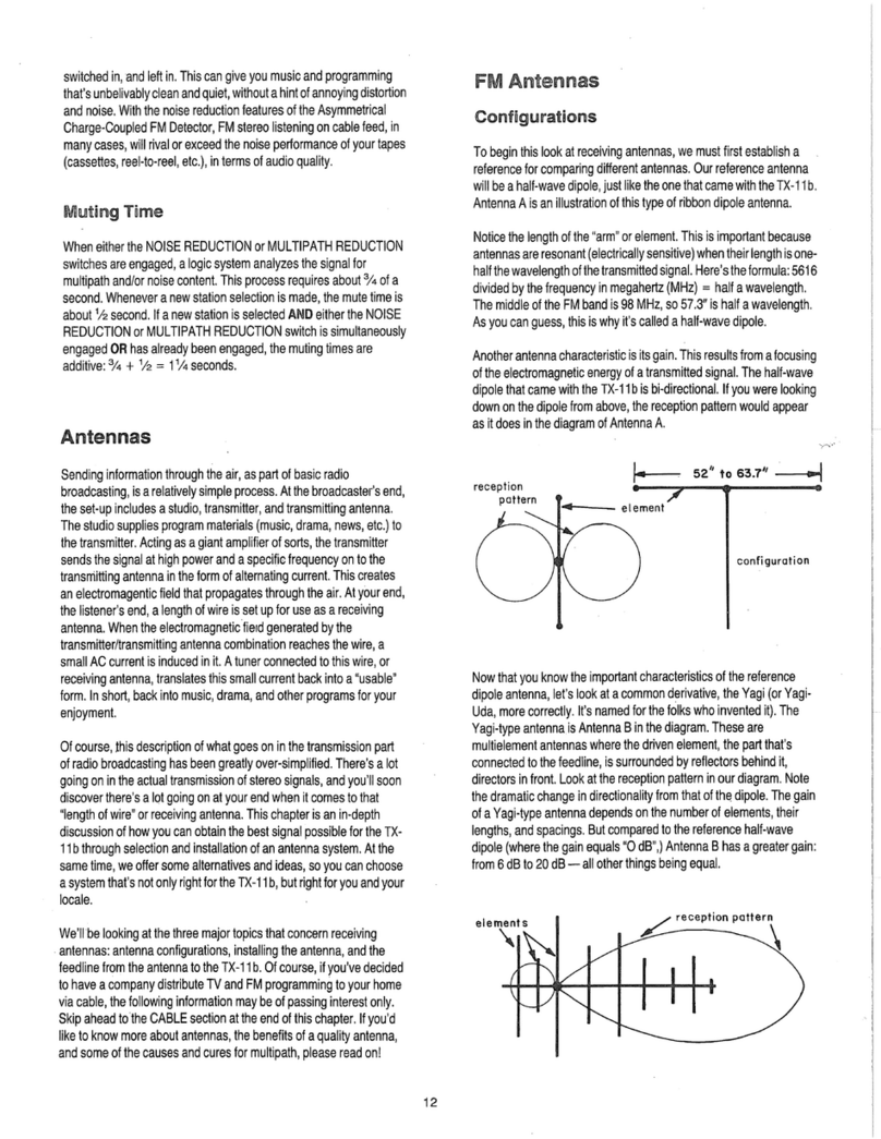
Antenna
A isan
illustration
of
thistype
of
ribbondipoleantenna.
Notice
the
length
ofthe
"arm"
or
element.This
is
importantbecause
antennas
are
resonant(electricallysensitive)whentheirlength
is
one-
half
the
wavelength
ofthe
transmitted
signal.
Here's
the
formula:
5616
divided
bythe
frequency
in
megahertz(MHz)
=
half
a
wavelength.
The
middle
oftheFM
band
is98
MHz,
so
57.3"
is
half
a
wavelength.
As
youcan
guess,
this
iswhy
it's
called
a
half-wave
dipole.
Another
antennacharacteristic
isits
gain.
Thisresults
from
a
focusing
of
the
electromagnetic
energy
ofa
transmitted
signal.
The
half-wave
dipolethatcamewith
the
TX-11
bis
bi-directional.
Ifyou
werelooking
down
onthe
dipolefromabove,
the
receptionpatternwouldappear
asit
does
inthe
diagram
of
Antenna
A.
reception
pattern
52"
to
63.7"
configuration
Now
that
you
know
the
importantcharacteristics
ofthe
reference
dipoleantenna,let'slook
ata
commonderivative,
the
Yagi
(or
Yagi-
Uda,
morecorrectly.
It's
named
forthe
folks
who
invented
it).
The
Yagi-typeantenna
is
Antenna
Binthe
diagram.These
are
multielementantennaswhere
the
drivenelement,
the
partthat's
connected
tothe
feedline,
is
surrounded
by
reflectorsbehind
it,
directors
in
front.Look
atthe
receptionpattern
inour
diagram.Note
the
dramaticchange
in
directionalityfromthat
ofthe
dipole.
The
gain
of
a
Yagi-typeantennadepends
onthe
number
of
elements,their
lengths,
and
spacings.
But
compared
tothe
reference
half-wave
dipole(where
the
gainequals
"0
dB",)
Antenna
Bhasa
greatergain:
from
6dBto20dB—all
otherthingsbeing
equal.
receptionpattern
12

The
practical
consequences
of
changes
in
gain
and
directionality
are
several.First
of
all,
while
the
referencedipolewillusuallydeliver
enoughsignals
for
goodreception,
is
"good"goodenough?Consider
that
the
19
kHz
pilot
signal
the
tuneruses
to
sense
a
stereobroadcast
is
transmitted
at
1/1
Oth
the
power
ofthe
signalcarrier.
If
thispilot
signal
is
lost,stereogoesaway.
Ifthe
pilotsignal
is
degraded,
so
will
be
the
stereoseparationbetween
the
left
and
rightchannels.
A
strong
signal
is
alsonecessary
to
reducenoise:noiseassociatedwithsignal
transmission,
and
noisefrom
localized
sources
of
interference.
Directionality
can
alsoreduce
the
strength
of
signalscoming
in
from
elsewhere.Thisincludesother
FM
stations,multipathreflectionsfrom
the
stationyou'relistening
to,
even
the
blender
inthe
kitchen.
Installations
Thissubject
is
prettystraightforward.
Allyou
reallyneed
to
know
is
that
the
higher
the
antenna,
the
better.
Height
is
important
because
radiowavestravel
ina
straightline,
or
line-of-sight.
If
yourantenna
is
free
and
clear
of
obstruction,
it
willperformbetter,
and
you'llgain
signal
strength.
Height
is
alsoimportantbecauseradiowavesbounce.Theybounce
off
hills,
buildings,
even
offthe
ground
in
front
of
your
antenna.
When
a
bouncedwavegets
to
yourantenna,
ithas
travelled
a
slightlylonger
paththan
the
line-of-sightwave,gettingthereslightlylater.
The
result
is
phase
distortion,
usually
the
loss
of
stereo
reception,
in
other
words:
the
dreadedmultipath.
The
higher
the
antennafrom
the
ground,
the
lesssusceptible
itisto
other
interference,
as
well.
A
roof-mountedantenna
is
muchlesslikely
to
"hear"vehicleignitionnoisefrom
the
street,
or
inducedinterference
within
the
home:
from
vacuumcleaners
tothe
kitchenblender.
Feedlines
Feedlines
canbe
compared,
ina
way,
tothe
cablesthatinterconnect
the
differentcomponents
in
yourstereosystem.
If
thesecables
and
cords
areof
poorquality
or
condition,perhapspoorlyinstalled,even
the
bestaudiocomponentswill
not
sound
as
good
as
theyshould.
It's
the
samewithantennafeedlines.
Youcan
cancel
any
advantage
from
height,
or
from
having
a
multielement,high-gainantenna
ifthe
connectionsbetween
the
antenna
and
tuneraren'tright.
Thetwo
commonfeedlinechoices
are300ft
twinlead
(alsoknown
as"TV
antennawire"),
and
7511
coaxialcable.There
are
sometrade-offs
whendecidingwhich
feedline
is
best
touse
withyourantenna
system.
300ohm
TWINLEAD
The
majoradvantage
to300ft
twinlead
is
thatit'sinexpensive,
and
if
it's
properlyinstalled,signallosseswithin
itare
reasonable(about
1.25
dBper
100
feet
at
100
MHz).However,
ifthe
twinlead
is
poorly
installed,
itcanact
like
an
antennaitself,degrading
the
performance
of
the
rest
of
yourset-up
by
picking
up
extraunwantedsignals,
and
interferencenoise.Twinleadrequirescarefulrouting,
and
must
be
insulatedfromeverythingmade
of
metal,likegutters,otherwires,
etc.Plus,
ifit
rains
in
your
neighborhood
like
it
does
in
ours,signal
losses
gowayup
with
wet
twinlead.
75ohm
COAXIALCABLE
Compared
to
averagetwinlead,
75ft
coaxialcable
is
moreexpensive,
and
it's
a bit
harder
for
signals
toget
throughcoax(about
3.5dB
loss
per
100
feet
at
100
MHz).
The
75ft
impedence
ofthe
cablemeans
a
matchingtransformerwillhave
tobe
installed
atthe
antenna(not
atthe
TX-11
b;ithasa75ft
connector
onthe
rearpanel).
The
realadvantages
to
coaxialcable
are
that
it's
not
prone
to
pick
up
extra
noise
and
interferencebecause
it's
shielded,
and
doesn'tsuffer
much
inwet
weather.Also,
you
don'thave
tobeas
carefulabout
routing,
so
installingcoax
is
mucheasier.
Antenna
Choices
As
we'vesaid,dipoleantennastend
tobe
susceptible
to
noise
because
they
aren't
very
directional,
and
because
they're
usually
mountedinside
the
home.Depending
on
yourspecificarea
and
location,signalstrengthwill
be
adequate
at
best.This
isduetothe
lack
of
directionality
and,
in
most
cases,
height
ofthe
antenna.
But
there
are
someadvantages,including
low
cost.
Inall
fairness,
the
type
of
dipoleantenna
we
providedwillwork
well
in
manydifferent
places
and
situations.
It
should
at
least
be
used
soyoucan
start
enjoying
FM
programmingrightaway,beforesettling
on
another
antennasystem
or
commercialcable.
It
should
be
pointed
out
that
the
ribbondipoleantennathatcame
with
your
tunerisn't
the
onlystyle
of
dipoleantenna.There
are
other
dipoleswhich
you
installoutdoors.Thesedipoles
can
overcomesome
of
the
problemswhichnormallymake
the
dipole
a
mediocreantenna
choice.
RABBIT
EARS
Unfortunately,
rabbit
ear
antennas
have
the
same
disadvantages
of
the
half-wavedipole.
Onthe
otherhand,rabbitears
canbe
tuned
by
adjusting
the
"ears"
tothe
wavelengths
ofthe
stations
you
listen
to.
Remember,
a
halfwavelength
atthe
bottom
endoftheFM
band
is
63.7";
atthe
upperend,it's52".
Youcan
easilydetermine
the
right
length
of
each"ear"needed
fora
particularstation.Also,
the
orientation
of
rabbit
ears
is
easy
to
change,
unlike
the
dipole
which
is
usuallystuck
toa
wallsomewhere.Movingrabbitearsaround
is
simple.Changingantennasfrom
one
wall
to
another
will
work,
but
thatisn't
the
whole
story.
Rabbit
ear
antennashave
one
more
disadvantage:
notas
muchgain
asthe
dipole.Also,check
toseeif
the
rabbitearshave
a FM
trap
to
removepossible
TV
interference.
All
thingsconsidered,rabbitearswillprobably
doa
better
job
than
the
half-wavedipoleincludedwithyourtuner.
INDOOR
FM
ANTENNAS
There
area
number
of
"blackbox"
or
table-top
FM
antennasavailable.
They'reessentiallyrabbitears:
youcan
tunethem
for
particularparts
of
theFM
band;
youcan
changetheirorientation(electrically).Losses
in
gain
are
about
the
same
as
rabbitears,
in
comparison
tothe
reference
dipoleantenna.
13

TV
ANTENNAS
If
a TV
antenna
is
mountedhighenough
and
connectedwith
a
properly
installedfeedline,
it
shouldresult
in
moreavailablesignal
than
the
antennaswe'vetalkedabout
so
far.Perhaps
notas
much
signal
asa
directional
FM
antennabecause
TV
antennas
are
broadband
(54MHzto
216
MHzfora
VHP
model).However,some
TV
antennashave
special
provisions
for
receiving
FM
signals,
while
the
rest
ofthe
antenna
is
used
for
VHP
TV
reception.Thatcould
be
more
moneythanyou'dwant
to
spend,unlessyou'reusing
the
antenna
for
both
TVandFM
reception.
If
you
alreadypossess
a TV
antenna,
orare
planning
to
hook
uptoa
master
antennasystem
inan
apartmentbuilding
or
condo,
it
might
not
work.Some
TV
antennashave
anFM
filter
built-in
to
rejectexactly
the
samesignals
you
want
to
hear.
Ifyou
fallinto
the
group
of
people
who
alreadyhave
TV
antennasinstalled
in
theirhomes,there
are
still
some
things
youmay
want
todo
before
adding
a
splitter
to
supply
signals
forthe
TX-11
b.
You'veovercome
oneofthe
costs
inan
antennasystem
by
having
the
antenna,
but
possiblereinstallation
andnew
feedline
maybe
desirable,evennecessary,
for
proper
performance.
It
willprobablyalsorequirereaiming
the
antenna.That
couldcreatesomeproblemswhichcoulddegrade
theTV
reception.
Thismeansyou'dhave
to
install
an
antennarotator.
A
rotator
allows
almost
infinite
realignment
ofthe
antenna
to
produce
the
best
signal
possible
for
stations
you
want
to
hear(andsee)
ona
station-to-station
basis.
OUTDOOR
FM
ANTENNAS
When
mounted
and
connectedproperly,
a
directionaloutdoor
FM
antenna
can
provide
the
bestsignal
of
all,with
the
lowestinterference
and
noisefactor.
The
greatestdisadvantage
to
thissystem
isthe
cost
of
the
antenna,
mounting
hardware,
anda
rotator.
The
rotator
isan
absolutenecessity
ifyou
want
to
pointthesehighlydirectional
antennas
in
morethan
one
direction.Most
FM
antennas
of
thistype
tend
tobe
evenmoredirectionalthan
a lotofVHFTV
antennas,with
or
withoutspecialprovision
forFM
reception.
Inany
outdoor
installation,
the
cost
ofa
groundrod,feedline,
and
insulatorsmust
also
be
figuredinto
the
totalprice
ofthe
antennaset-up.
The
combined
totals
can
quickly
addup.
Otherthandirectional
FM
antennas,there
are
outdoordipole
antennas
that
can
provide
many
ofthe
same
benefits,
ata
somewhat
lower
cost.You'realreadyfamiliarwith
the
half-wavedipolewhich
can
also
be
calledsingledipoleantennas.
The
dipolethatcamewith
the
TX-11
b is
meant
tobe
usedindoors,
andhas
justthat
one
upper
arm,
or
element.
The
virstvariation
on
this
dipole
isan
antennathat
is
really
two
singledipoles
setat
rightangles.
It
works
the
same
way
as
the
single
dipole
but
instead
of
picking
upthe
majority
of
signals
in
two
directions,
the
dual
dipole
will
pick
up
signals
ina
modifiedomni-
directionalpattern.
Another
outdoor
variation
isthe
S-curve
omni-directional
antenna.
For
all
intents
and
purposes,
the
S-curveantenna
is
just
a
single
dipolebentinto
a
"S"
shape.
The
change
inthe
shape
ofthe
antenna
makes
its
pick-uppattern
a
littlemoreomni-directionalthan
the
reference
dipole.
Other
than
the
changes
in
pick-up
patterns,
both
thesemodifieddipoles
offer
moregainthan
the
reference
dipole.
On
topof
that,theseantennas
maybe
installedhighenough
to
reduce
the
possibility
of
localinterference,
and
some
multipath
interference
problems.
When
totalling
up
costs
for
hardware,these
two
outdoordipoles
eliminate
the
need
ofa
rotator,
but
will
still
require
the
proper
mounting
hardware
and
feedlines.
You
mustweigh
and
compare
the
costs
and
benefits
of
directional
vs.
omni-directionalantennasystemsinstalled
outdoors
onthe
results.
It
could
bethe
omni-directionals
willgive
superiorcoverage
and
signalquality
in
yourarea,making
a
directional
antennaunnecessary.
Onthe
otherhand,
the
directional
FM
antenna
may
bethe
onlyroute
togo
because
of
severelocalizednoise
and
multipathinterferenceproblems.
The
point
is
thatactualantenna
selection,over
and
above
the
fact
someantennas
are
"better"than
others,must
be
made
onan
area-by-areabasis.Terrain,transmitter
locations,
and
your
relation
to
them
will
bethe
deciding
factorswhen
figuring
out
whichsystemwillreceive
the
signals
the
best.
Installation
Choices
INDOORINSTALLATION
For
obviousreasons,indoorinstallations
arethe
easiest
todo.It
doesn't
involvemuch
to
stick
the
dipolethatcamewith
the
TX-11
b
on
a
wall.
But
remembersome
ofthe
drawbacks
to
indoor
antennas:
1)
height,
and2)
possibleproblemswithinterferencefromcars
on
the
street
and
smallelectrics
inthe
kitchen.Plus,antennaheight
is
essential
to
goodsignalstrength
and
signal-to-noiseratio.
An
indoorantenna
can
work
justfine
if
you're
ina
taller
building
with
good
"line-of-sight"
tothe
area's
FM
transmittingtowers,
or
other
places
where
youget
clean
signals
fromyourfavorite
stations.
If
you'vebeenlistening
toFMon
anotherreceiver
in
yourhome,
you
might
geta
veryroughidea
how
manystationscould
be
available.
However,
your
TX-11
b isa
tunerwithimpeccableperformance,
capable
of
makingstationsthatweretotallyobnoxious
dueto
noise
and
distortion,soundgreat!Thisalonewillallow
youto
experience
allthe
pleasure
ofFM
stereolistening,with
a
less-than-ultimate
antenna.
Ifyou
can't
geta
trulylistenablesignalfrom
a
dipole
or
other
type
of
indoorantenna,there
are
otheroptions.
OUTDOORINSTALLATIONS
Properly
done,outdoorinstallations
can
offer
vastly
improvedsignal
quality
over
indoorantennas.
But
there
isthe
cost,
andthe
actual
effort
of
putting
itallup.
Another,perhapsmostimportantconsideration,
is
SAFETY.Safety
is
veryimportant
in
planning,
setting-up,
and
using
your
antennasystem.Withthat
in
mind:
•
Don't
runthe
risk
of
having
a
bolt
of
lightning
—
natural
orman
made
—join
you,your
tuner,
and
yourstereosystem
inthe
living
room:
A)
Keep
the
antenna,mast,boom,
guy
wires,feedline,whatever
away
from
all
powerlines.Thatincludes
the
linesfrom
the
powerpole
tothe
house.DON'TEVENTHINKABOUTPUTTING
ITUP
WHERE
r
14

IT
COULD
FALL
INTO
POWER
LINES!
B)
Make
sure
the
antenna,
mast,
and
boom
are
properly
grounded
with
a
largeconductor-wire
running
from
the
antenna
toa
ground
rodinas
short
a
path
as
possible.
NOTE:
10-gauge
copper,8-gaugealuminum,
or
12-gauge
copper-
cladsteelwireshould
dothe
job.However,
the
heavier
the
better.
Certainmasts
canbe
grounded
bya bar
attachment
toa
groundrod,
with
a
strap
asa
connector.
This
isa
superiorgroundattachment
if
the
mast'sbaserests
onthe
ground,
or
specialgroundplate.
•Use
stand
off
insulators
to
keep
the
groundwireawayfrom
the
house.Spacetheseinsulatorsfour
tosix
feet
apartwherepractical.
It's
a
poorpractice
to
staple
the
wire
to
yourhouse.
•Usea
proper
antenna
discharge
unit
or
lightening
arrester,
mounted
as
close
as
possible
to
where
the
feedlineenters
the
house.Make
sure
the
arrestor/dischargeunit
is
securely
attached
tothe
ground
rod
with
the
heavy-gaugegroundingwire,insulatedwithstand
off
insulators
along
the
house.
•
NEVERground
the
antenna
(or
anything)
toagas
pipe.
Makesure
any
groundingschemeemploying
pipes
inthe
house
belong
tothe
water
system.
A
lightening
strike,instead
of
being
harmlesslyrouted
to
earth,
can
turnyourhomeinto
an
explodingsun.
•If
yourantenna
and
mastrequire
the
support
ofguy
wires,makesure
the
wires
use
in-line
insulatorsbetween
theguy
wire
and
roof.These
insulatorselectricallyisolate
the
supportwiresfrom
the
house.This
isn't
a bad
idea
even
iftheguy
wires
are
anchored
tothe
earth.
•
NEVER,
NEVER
work
onany
part
of
(andbestkeepcompletelyaway
from)
yourantennasystemduring
an
electricalstorm!Remember
to
disconnectyour
TX-11
b
from
the
antennaduringelectricalstorms,
too.
•
Anotherimportantitemrelated
to
personal
safety
is,of
course,
to
be
careful
when/if
you
startclimbingaround
on
roofs
andthe
like.
Don'tmakeyourantennainstallation
bethesetupfora
quickfall.
Ground
Rod
When
it
comes
tothe
ground
rod
we've
beentalkingabout,thismetal
rod
should
be
drivendeeplyinto
the
earth.
A
ground
rod
drivenonly
two
feetdownusually
has
three
to
fourtimes
the
resistance
ofa
ground
rod
driven
ten
feetdeep.That's
the
key:
low
resistance.
The
object
ofall
thisgrounding
isto
give
a
lighteningstrike
the
easiest
path
tothe
earth,
not
your
home.
Aswe
said,makesure
youusea
lightening
arrester
or
dischargeunitthat'sattached
tothe
ground
rod
with
the
sameheavy-gaugewireusedfrom
the
antenna
tothe
discharge
unit.
BetweenAntenna
and
Tuner:Feedlines
Last
butnot
least
in
considerations
for
putting
upan
outdoorantenna
is
the
feedlinewhich"connects"
itall
together.Earlier
inthe
chapter,
we
talked
about
the
problems
and
merits
of300
0
twinlead
and75(1
coaxialcable.There
are
some
additional
thingsthatcouldrelate
to
your
finalchoicebetween
the
two.
300
0
TWINLEAD:Remember,it'slessexpensive
andhasthe
lowest
line
losseswhendry,
and
properlyinsulatedfrom
the
house
and
mast
withstand
off
insulators
specially
designed
for
twinlead.Twinlead
mustalso
be
kept
away
frommetalgutters,windowframes
and
other
wires.
Of
course,
it
should
be
keptwellawayfrom
power
lead
ins.
Thereshould
be
over
an
inchspacingbetweenotherwires
inthe
home
and
stereosystem
—
more
is
better.Avoiding
the
obstacles
we've
mentionedwill
add
overalllength
tothe
lead
in,and
some
of
thesedetourswillcause
additional
line
losseswhenwet.Also
rememberthattwinleadmust
be
wellinsulatedfrom
the
antennamast,
house,etc.withstand
off
insulators.Theseinsulators
are
available
ina
variety
of
attachments:
the
shaftscometerminated
in
screw-in
units,masonrynails
for
brick
and
concrete,
and
nail-ins
to
suit
any
installationneed.
The
stand
offs
should
be
usedabouteveryfourfeet
with
twinlead.
In
addition,
special
careshould
be
takenwhenrunning
twinleadthrough
a
wall,
or
bringing
it
indoorsthrough
a
window
frame.
Use
a
walltube
or
framebushing
to
isolate
and
insulate
the
twinlead
from
the
wall/framematerials.This
can
avoidpossiblesignalloss
and
interferenceproblems
at
thispoint
inthe
installation.
Ifthe
total
run
from
the
antenna
to
your
TX-11
b
exceeds
300
feet,
a
preamp
atthe
antennamight
be
needed
to
boostsignals
inthe
line.
75
n
COAXIAL
CABLE:
Coaxialcable
isthe
easiest
ofthetwo
feedlinechoices
to
install,
andhas
somedistinctadvantages.
Obstaclesthatwouldseriously
affect
the
performance
of
twinlead
canbe
virtuallyignored,
and
since
coaxialcable
is
shielded,
interference
is
muchless
ofa
problem.
The
onlyrealdrawback
isthe
cost,
andthe
need
ofa
preamp
to
boostsignal
in
runsover
120
feet.
Actually,
120
feet
isa
prettylong
way
fromyourantenna
tothe
tuner.
Also,
sincecoax
is
easier
to
install,
the
cost
of
cable
and
preamp
(if
needed)
canbe
made
upina
moreeffortlessinstallation.Plus,
the
benefits
of
loweredlosseswhenwet,
and
reducedinterference
can
be
an
additional
incentive
touse
coaxialcable.Coaxialcable
canbe
easilybroughtinto
the
house
tothe
tunerwithout
the
need
of
special
fittings
or
passages.
Fewer
stand
off
insulators
canbe
used
inan
installation
usingcoaxialcable
asa
feedline:
one
aboutevery
sixto
eight
feet.
SomeAdditionalHints
•
Ifyou
decided
to
chimney-mount
the
antenna,
route
the
feedline
away
from
the
chimneyoutlet
byat
leastthreefeet.Heat,smoke,
and
residue
can
breakdown
the
insulation
of
bothtwinlead
and
coaxial
cable.
•
If
you'replanning
to
attachyourantennasystem
toa
chimney,make
sure
the
chimney
hasthe
structuralstrength
to
support
it.
Thoroughly
inspect
the
chimney
for
loosebricks,brokenmortar,cracks,
or
other
conditions
thatcouldindicate
a
poorstate
of
repair.
•DONOTusea
metalchimneystovepipe
to
support
an
antennaset-
up.
Otherthan
the
considerations
of
structuralsupport,
a
lightening
strike
could
turnyourstoveinto
a
giantelectrode.That
can
happen
with
a
metalpipechimney,even
ifthe
antennaitself
has
beenproperly
grounded.
•For
those
whoare
located
a
considerabledistancefrom
anyFM
transmitting
facility,
a
tower
or
mast
maybe
necessary
to
obtain
better
line-of-sight
and
clearance
forthe
antenna.
If
youroutdoor
installation
fits
intothiscategory,
pre-made
masts
and
towerkits
are
available
from
many
TV
stores
and
electronic
supply
shops.Despite
the
cost,
a
30-to-50
foot
mast
or
tower,
in
combinationwith
a
good
high-gain
15

antenna,
can
provide
a
quality
signal
forthe
TX-11
b.
Even
in
"fringe
areas"
wheregoodreception
is
normally
a
realproblem.
Be
sure
any
mast
or
towerset-up
is
properlysecuredwith
guy
wiresupports
(if
needed),
and
installedwhere
it
can'tfallintopowerlines,
the
neighbor'sgreenhouse,
or
whatever.
Cable
When
we
talkaboutcable,
we
mean
a
masterantennasystem
supplying
high
quality
TVand
FM
signals
to
individual
homes
(or
"subscribers").
The
signals
are
sent
viaa
distributionnetwork
of
wires
and
lineamplifiers.
The
wire,
or
cableportion
ofthe
system,
canbe
likened
toa
telephonedistributionset-up.
The
lineamplifiers
are
used
to
boostsignals
at
certainintervals
inthe
lines,muchlikeusing
an
antenna
preampwithlongfeedlines
in
your
own
antennasystem.
Originally,
communitycabletelevision
(CATV)
wasa
response
tothe
problems
of
poor
or
nonexistantreception
ofTV
signalsbroadcast
"clear
air."Theseproblemscould
be
caused
by
distance,terrain,
or
even
just
remotelocations(out
of
range,
or
fringeareareception).
The
cablecompanychooses
a
highhilltop
or
otherlocationwhere
they
can
obtain
the
best
line-of-sight
tothe
area'stransmittingtowers.
Thissite
is
known
in
cableparlance
asthe
"headend."This
is
where
high-gain
antennas
and
amplifiers
are
used
to
receivedistant,weak,
or
otherwise
unreceivable
signals.
The
signals
are
passed
onto
line
transmitters,
then
tothe
distributionpart
ofthe
cablesystem.
At
yourhome,signalsfrom
the
cable
inthe
street
arefedto
your
TV
set.
Ifyou
want
FMas
well
asTV,the
signals
are
split
with
oneset
going
totheTV,the
other
to
your
TX-11
b.Of
course,
youcanbe
connected
to
justreceive
FM
signals,
without
the
videohook-up.
An
FM
feed
mayusea
specialfilter
to
remove
TV
interference,
orto
prevent
you
from
illegally
receiving
FM
signals
from
a
single
TV
feed,
an
FM
trapmight
be
installed
atthe
street.When
the
cablepeople
connectyour
TX-11
btothe
system,
any
necessary
filters
are
installed,
any
traps
are
removedfrom
the
line.Thisbrings
up
somethingelse
again:
it's
not
legal
totap
into,
or
hook
a
commercialcable
up
yourself.
It
must
be
done
bythe
cablecompany.
As
mentionedearler
in
thismanual,feedlines
for
cable
TVareall75fl
coaxialcable,
so
connections
canbe
madedirectly
tothe
TX-11
b's
75
ft
antennainput.However,
the
usualprocedure
isforthe
cable
companyinstaller
to
connect
a
tunerwith
a
matchingtransformer
(75
ftto300ft)toits300ft
inputs.
Aswe
suggested,
askthe
installer
if
it
would
be
possible
tousethe
TX-11
b's75ft
input.
The
benefits
of
using
a
commercialcable
to
supplyhighquality
FM
stereo
signals
forthe
TX-11
bare
many.
For
example,
you
don'thave
to
worry
about
the
cost
and
effort
of
installing
a
goodoutdoorantenna.
You
don'thave
to
worry
about
the
performance
of
such
a
system
after
all
thatwork,either.
Asa
rule,cablecompanieshave
a
one-time
installationcharge,then
a
monthlyfee.
The
cost
of
cableservice
can
depend
on
manyfactors,
and
variesfromsystem
to
system.Costs
will
run
higher
fora
commercial
cable
feed
for
both
TVandFM
service,
less
forFM
only.
Other
thanopening
upanew
world
for
enjoyment
ofFM
programming,
commercialcable
can
open
anew
world
of
audio
for
your
TV
set.Many
cable
systemsprogrampremiummovie/filmserviceswith
spectacular
stereo
soundtracks.
The
videoportion(withstandardaudiocarrier)
is
broadcast
onthe
cable
fortheTV
set.
A
separatestereosoundtrack
is
broadcast
intheFM
band.
The
TX-11
b
receivesthesesignals
and
turnsyour
living
room
into
a
real
theater
or
concert
hall.
Younot
only
see
greatartistsperformingyourfavoritemusic,
but
hear
it
like
you
werethere.Thisset-upfreesyour
TV
from
its
burden
of
having
a
tiny,
limited-response,internalaudio
ampand
speaker.
AM
Antennas
The
Motorola
CQUAM™
AM
stereosystemrequires
a
stronger
and
cleanersignal
to
takefulladvantage
ofthe
benefits
ofAM
stereo.
Two
AM
antennas
are
includedwithyour
TX-11
b:a
longwireantenna
and
a
loopantenna.
We
havedetailed
the
benefits
of
eachtype
to
help
you
select
the
bestantenna
for
yourenvironment.
AM
WireAntenna
The
longwireantenna
is,
undermostcircumstances,
the
preferred
antenna.
Itis
able
to
receivesignalsfromfartheraway
and
willreceive
normally
distantsignalsmuchstrongerthan
the
smallloopantenna.
Thiswireantenna
is
alsomoreeffective
for
eliminatingnoisesthat
occur
ininthe
atmospherethat
isata
distancefrom
the
tuner.
The
long
wire
orientation
isnot
particularlycritical.Sincethisantenna
is
used
for
maximumsensitivity,
ifyou
liveveryclose
toa
strong
transmitter
youmay
overload
the
front
endof
yourtunerwiththis
antenna
and
willwant
totrythe
loopantenna.
AM
LoopAntenna
There
are
certainconditions
in
which
the
loopantennaworksbest.
It
has
betternoiserejection
for
locallygeneratednoise
-
noisesthat
are
generatedclose
tothe
tuner
andmay
soundlikebuzzes
or
hum.
Itis
able
to
reducethesenoises
fortwo
reasons:
1)
Thisantenna
is
directional,
and2)ithasa
lowerdrivingimpedancethan
the
wire,
so
it
tends
to
short
circuit
this
kind
of
interference
readily.
The
loopantennapicks
upthe
signal
at
rightangle
toan
axispassed
through
the
loop.
Ifyou
want
to
pick
upa
radiostationthat
isdue
north,
orient
an
axisthatpassesthrough
the
loop
at
rightangles
to
north.
If
you
wereholdingthisantenna
asifit
were
a
gun,
you
wouldpoint
it
at
the
station.Again,
the
loopantenna
isfor
maximumrejection
of
locally
generated
interference.
Ultimate
AM
Antenna
For
those
ofyouwho
wouldlike
to
take
the
time
to
build
the
ultimate
AM
antenna,
we
offer
the
plansthatfollow.Thisantennaincorporates
the
benefits
of
both
the
wire
andthe
smallloop.
It
willhave
the
noise
reductioncapability
ofthe
smallloop
for
locally
generated
noise,
the
noise
reductioncapability
ofthe
wire
for
atmosphericallygenerated
noise,
it
will
be
extremely
sensitive,
andit
will
be
very
directional.
Thisantenna
is
basically
a
home-built
loop
whosearea
is
measured
in
squarefeetratherthansquareinches.
To
buildthisantenna:
1)
Construct
a
woodcrossframethatmeasures
12"
from
point
to
16
I

point.(17"
eachcrossbar).
2)
Secureframe
toa
base.
3)
Wrapframewithfour
turns
ofthe#22
insulated
solid
wire.
4)
Twistwireendstogetherapproximately
2
turns
per
inch.
5)
Stripwireends
1/2
inch
and
connect
toAM
terminals
on
back
of
TX-11b.
Drawing
A
shows
a
completedantenna.
Drawing
B
detailsconnections
forall3
antennas.Don't
be
afraid
to
experiment
to
discover
the
best
antenna
for
your
location.
_—
_
frame
— —
wire
loop
17"
base
B
SomeOtherThoughts
The
bulk
of
thischapter
has
beendevoted
to
explanations
and
comparisons
of
differentantennas
and
antenna-systeminstallation.
We've
providedinformation
to
help
you
make
a
decision
on
what
can
provide
the
bestsignalpossible
forthe
TX-11
b,
usingyour
own
antenna.
It's
pretty
obvious
thatmuch
time
and
attention
canbe
spent
in
pursuit
ofa
goodsignal
by
installing
a
goodantenna.Especially
if
you
live
far
awayfromradiostations,
orinan
areawithclassic
receptiontroubles.Beforethrowing
up
yourhands
and
despairing
the
thought
of
installing
a
morecomplexoutdoor
antenna,
wait
a
minute!We'dlike
to
remind
you
that
the
TX-11
bhas
uniquefeatures
and
performance,
making
the
choices
of
antennas,feedlines,
and
installationmethodslesscriticalthanwithvirtually
any
othertuner.
Still,
to
realize
the
maximumquality
of
performance
and
programming
excellence
offered
by
stereostations,you'llhave
to
pull
the
best
signalpossiblefrom
theairforthe
TX-11
b.For
thatreason,
youmay
want
to
select
oneofthe
betterantennaoptions.
If
it
comesdown
tothe
outdoorvariety,with
the
effort
and
cost
involved,
you
might
be
better
off
having
the
antennasysteminstalled
by
professionals.Thesefolks
know
alltheinsand
outs
of
qualitysignal
reception
for
yourspecificarea
and
circumstances.Plus,they
doall
the
climbingaround
onthe
roof.
A
companythatspecializes
in
this
type
of
work
can
give
youan
estimate
of
whatthey
feel
ajob
like
it
couldcost,allowing
for
somefurthercomparison
of
prices.
A
company
thatdoes
this
type
of
workoften
hasa
retailoutletthatstocksgood
antennas,materials,
andthe
hardwareyou'llneed
(ifyou
decided
to
do-it-yourself).
Taketime
to
checktheseservices
out
beforegiving
in
or
giving
up.
dipole
ribbonantenna
OO
17
r

Appendix
SECTION
1
FM
StereoSignals
andthe
Asymmetrical
ChargeCoupled
FM
Detector™*
FM
radiostationsstarted
life
broadcasting
a
carrierfrequency
modulated
by
music.When
you
listen
to"FM
108",
whatyourtuner
is
receiving
is
thatfrequency
—108
MHz
(megahertz,
or
millions
of
cycles
per
second)
—
modulated
bya
musicspectrumfrom
30Hzto
15
kHz
(KiloHertz,
or
thousands
of
cycles
per
second).
The
Federal
Communication
Commissionensures
(bylawand
threat
of
fine)
that
the
rock
music
onone
station
won't
interferewithclassics
onthe
next.
When
radiostationscameunderpressure
to
deliverstereosound,
somesystem
of
broadcasting
two
signals,
short
of
setting
up
another
station,became
necessary.
Earlyexperimentswereactually
tried
with
one
channel
onFM,the
other
onAM.
Needless
to
say,someother
solution
hadtobe
found.
One
constraint
ofthe
stereobroadcast
system
requiredthattableradios
geta
usablemonosignal
— not
just
the
left,
or
just
the
rightchannel.What
was
finallyadopted
and
approved
bytheFCCwasa
broadcastingsystemwhereboth
channels
(L+R)
wereavailable
as
usual.
To
supply
stereo,
a
differencesignal
(L-
R)was
developed
and
used
to
modulate
anothercarrier
at38
kHz.
Now
forthe
first
complication.
It
turns
out
thatbroadcastingthat
signal
in
stereorequired
too
muchfrequencydeviation(thedifference
between
the
necessarysignal
andthe
carrier),
sothe38kHzL-R
carrier
is
suppressed
anda
muchsmalleramplitude
19
kHz
pilot
is
added.
Mono
radios
use
only
the
firstblock
ofthe
signal.
The
SCA,
or
SubsidiaryCommunicationAuthority
signal,
is
oftenleased
to
companiesthat
specialize
in
commerical-free
backgroundmusic
for
stores,dentist'soffices,plusspecialprogramming
forthe
visually
impaired
—
evenforeignlanguagebroadcasts.
To
receive
anSCA
service,
a
specialtuner
is
needed.Thesesignalscan't
be
picked
up
ontheTX-11b.
The
components
ofthe
transmitted
FM
stereosignalthatconcerns
us
are
L+R
signals,
and
mostimportantly,
theL-R
signals.
The
graphic
representation
ofa
sample
FM
signal
shows
the
various
relationships
ofthe
different
signal
components
in
frequency
and
amplitude.
There
aretwo
morethings
you
shouldknow:
1)
actually,only
15%
of
the
L-R
signal
is
differentthan
the
L+R
signal;
2)theL-R
portion
of
the
transmittedsignal
is
veryprone
to
mishapsbetween
the
transmittingtower
and
your
TX-11
b.
It'sthissignalcomponentthat,
when
degraded,causesnoise
and
distortionproblems,usually
induced
by
multipath
reflections
off
hills,
buildings,
the
ground...
whatever.
The
AsymmetricalCharge-Coupled
FM
Detectoroperates
principally
on
theL- R
signalcomponents,improving
it
from
10
dBto23dB.
However,
itcan
onlyimprove
the
L+R
component
by1dB.Ifyou
kHz
15kHz
23kHz
19
kHz
(pilot)
FREQUENCY
«-
SCA
at
67kHz
receive
the
L+R
signalcomponentswell,
but
suffer
frompoor
L-R
reception,
the
AsymmetricalCharge-CoupledDetectorwill
drastically
improve
the
reception.
Ifthe
L+R
signal
is
poorlyreceived
as
well,
the
circuit
can
onlyhelp
a
little.
Degraded
L+R
reception
is
often
due
to
improper
or
inadequatesignal
strength.
Thiscouldindicate
a
distant
station,
orthe
need
ofa
betterantennasystem.
Almost
all
stereo
FM
receptionproblems
canbe
traced
to
poor
L-R
signals.
The
AsymmetricalCharge-Coupled
FM
Detector
is
extremely
effective
in
reducing
the
noise
and
distortionassociatedwiththistype
of
multipathinterference.
In
short,
itcan
providestereoreceptionthat
is
as
noise-free
asFM
broadcast
in
mono.Because
ofthe
nature
of
the
components
ofa
transmitted
FM
signal,
the
circuitcan't
significantlyimprove
a
poormonoprogram.
SECTION
2
AM
StereoSignals
andThe
UltraHigh
FidelityWideBand
AM
Stereo
Thistuner
is
absolutelyunique
in
that
its
basic
AM
performance
capability
is
essentiallyequal
to,andin
somecasessuperior
to,the
performancethat
FMcan
deliver.
AMis
inherentlyimmune
to
multipath
distortion,
the
primaryproblem
ofFM.
There
isno
fundamental
limitation
to
frequencyresponse,
distortion
or
noise
in
AM.
AM
systemshistoricallyhave
fallen
bythe
wayside
until
very
recently,
whenmanufacturershavetypicallyaddedthem
as
afterthoughts.
TheAM
systems
in
mostradiossoundterriblebecause
they
havebandwidththatextends
to2 or
3kHz;theyhavesignal
to
noise
ratios
inthe30sor
40s,instead
of
60s,70s,
or
80s;theyhave
distortionthat
is
usually3-8%
- not
high
fidelity
byany
means.
The
distortion
levels
in
this
machine
are
orders
of
magnitude
belowthat,
the
signal
to
noiseratio
isfar
superior,
andit
also
hasAM
stereo.
CQUAM™
AM
stereo
isa
brand
new
system
developed
by
Motorola.
The
wayit
worksbasically
is
that
a
signal
is
phasemodulated,
asub
carrier
is
phasemodulated
ontopofthe
regularcarrier,
anda
phase
detector
responsive
tothe
phasedeviation
of
thatcarrierseparates
out
the
left
andthe
rightchannelsignals.
Theway
it's
done
is;
the
L+R
part
ofthe
stereo
signal
is
broadcast
as
amplitude
modulated
AM,
theL-Ris
broadcast
on
thatsame
carrier
asa
phase
modulated
signal.
It's
actually
FM
because
whenever
you
have
a
phase
modulation
you
have
a
corresponding
FM
deviation
and
whenever
you
have
anFM
deviation,
you
have
a
correspondingphasemodulation.
Soby
modulating
the
phase
and
18

having
a
phasedetector,we'reable
to
detect
theL- R
part
ofthe
signal.
AnAM
detector
is
absolutely
insensitive
to
phasemodulation.
An
FM
detector,
when
properly
constructed,
is
insensitive
to
amplitude
modulation,
sothe
phasedetectorpicks
outtheL-R
becauseit'sphasemodulated
and
ignores
the
L+R
component.
The
output
of
eachdetectorthen
is
composed
ofan
L+R
signal
andan
L-R
signal.
Those
two
signals
are
combined
inan
appropriatematrix
to
produce
a
left
anda
rightoutput.
In
addition
to
thatthere
isa
pilottonethat
is
broadcast
at25Hzat
4%
modulation
to
turn
the
stereodecoder
onoroffand
light
upan
indicator
light
toletyou
knowthat
youare
listening
to
stereo.
The
featuresthatthistuner
hasof
receiving
AM
stereo
are
vast.
Our
circuitry,unique
toall
circuits,
hasa25Hz
pilotcancelling
circuit.
Most
AM
receivers,
to
eliminate
the
25Hzfromtheiroutput,willsimply
put
ina
bandstopfilter
and
nothingbelow
25Hz
getsthrough.
Our
system
is
flatdown
to
below
20Hzby
using
a25Hz
pilotcancellingsignal
so
the
pilot
will
be
cancelled
and
will
not
appear
atthe
output
asa
low
frequencyundesiredrumble.
Inthe
absence
ofa25Hz
pilottone,
the
stereodecoderwillswitchoff.This
is
desirablewhen
the
tuner
is
receiving
a
signal
in
mono,otherwise
it
would
be
somewhatnoisier.
The
difference
in
noise
is
theoreticallyabout3dB,
in
practice
we
find
it'sabout
14dB.
However,it's
14dB
noisier
whether
the
signal
is
strong
or
weak.
It
actuallyworks
out
betterthan
it
doeswith
FM.
Because
when
the
signal
islowinFM,youcango
fromstereo
to
mono
orgo
from
an
unlistenablecondition
in
stereo
toa
listenablecondition
in
mono.With
AM
thatdoesn'thappen.
InAM,the
signalwillremain
eminentlylistenable,evenwhenswitching
to
stereo
ona
weak
station.
This
isthe
only
AM
tunercapable
of
15
kHz
response
and
bandwidth.
The
typical
AM
bandwidth
is
approximately
3
kHz;goodenough
for
speech
andnot
reallygoodenough
for
highfidelitylistening.High
fidelityrequires
15
kHzor
more.Thisradio
hasa
unique
IF
system
(intermediatefrequency).
Ithas
beencarefullydesigned
tobe
perfectly
flat
15
kHzon
eitherside
oftheIF
carrier.Mostotherradios
have
a
responsethat
is
flatmaybe
to2 kHzand
several
dB
down
at
3
kHz;
the
best
of
them
are
usually
10dB
down
at6
kHz.
The
TX-11
b
system
is
perfectly
flat
andyou
willimmediatelyhear
the
difference.
When
you
listen
toanAM
radio,
you
willhearsparkle,life-liketimbres
just
thewayyou
hearthose
sparkly,
life-like
high
frequencytones
when
you
listen
toFM.
Why
areall
othertuners
are
only
3 kH
wide?
The
mainreason
is
that
itis
very
difficult
to
design
a
wideband
AM
radio.
It
requiresheroic
efforts.
It
requiresthat
theAM
antenna
be
widebandwithhigh
selectivity;
it
requires
a
greatmany
IF
stages.
It
requires
anIF
tuning
mechanismthattunes
simultaneously:
the
oscillator,
the
antenna,
and
theIF
must
track;
almost
impossible
todo
with
modern
electronic
varactictunedsystems.
Intheold
days,
the
tracking
wasa
matter
of
capacitorgeometry(some
ofyou
mightremembertuningcapacitors
that
had
serratedmetalinterleavedfinger).
Itwas
relativelyeasy
to
make
those
track
well
upand
down
the
band
simple
because
itwasa
matter
of
doing
the
geometryright.They
hadan
interestingquasi-
eliptical
shape
to
them
as
theyrotated
inandoutof
mesh.Modern
varactictunedsystems
are
verydifficult
to
maketrackproperly,
so
difficult
in
fact
that
most
AM
radio
manufacturers
gave
upand
made
the
bandwidthvery,verynarrow.
By
doing
so,
front
end
varacticmistracking
was
masked
bythe
narrow
bandwidth.Evenoscillatormistracking,oscillator,
IFandRF
mistracking
was
almosttotallymasked.Eventodaywithmostradios
you
willfinddifferentfrequencyresponses
on
differentsegments
of
the
dial.
Thelowendofthe
dial
may
have
a
higheraudiofrequency
responsewhenmeasuredthan
the
high
endofthe
dial
that
isdueto
mistracking.What
wehadtodowasto
develop
a
veryaccurate
trackingsystem
forour
varacters,
and
thisincludedenclosingthem
in
a
verypowerfulfeedbackloop
to
makesurethattheytrack
and
were
in
fact,alsowideband.
The
goal
wasto
make
the
bandwidth
15
kHz:
same
asFM.
Now
an
immediatequestioncomes
up;ifthe
tuner
is
capable
of
such
fine
performance,whatabout
the
broadcasttransmitters?
A
survey
in
the
Seattleareaimmediatelydemonstratedthat
the
majority
oftheAM
transmitters
are
broadcastingsignals
outto
15
kHz.Almost
allof
them
have
signalsthat
goouttoat
least
12
kHz,many
to
beyond
15
kHz.
You
willnotice
it
immediately.
15
kHzisan
acceptedminimum
for
highfidelity,
andtheFM
system
that
weuseis
limted
to
15
kHzandit
stopsinstantly
ata
brickwall
at
15
kHz.
TheAM
system
isnot
quitethatmuch
ofa
brickwall
andthe
responseactuallycontinues
a
little
bit
beyond
15
kHz.
We
can'tmake
it
20kHz
becusethatwould
putthe
modulatedcarriersquarely
ontop
of
an
adjacentchannel.Channels
in
thiscountry
are
spaced
20kHz
apart.
Thistuner
has
incrediblespecifications.
IthasanAGC
rangethat
is
approximately
10
timesgreaterthan
a
standardradio.Thatmeans
that
ona
strongstation,
the
outputlevelfrom
a
strong
to
weakstation
will
remainessentiallyconstant;
it'll
behave
in
thatregardlike
anFM
system;
a
weakstationwon'tdrop
in
volume
andit
won't
be
susceptible
to
airplaneflutter,won't
be
susceptible
to
fading
theway
a
regular
AM
radiowould
be.
That's
No.
1.
No.2of
course,
isthe
wide
bandwidthwhichresultssimply
in
high
fidelity
because
it
picks
upthe
highfrequencycomponents
ofthe
music.
19

SECTION
3
Specifications
FM
TUNINGRANGE:
87.5
MHz-108
MHz
ANTENNA
TERMINALS:
75H
coaxialinput
INTERMEDIATE
FREQUENCY:
10.7
MHz
FREQUENCY
RESPONSE:
20Hzto
15
kHz,
± 1
dB
SELECTIVITY
(At400
Hz):
90dB
(narrow);
35dB
(wide)
CAPTURE
RATIO:
1.0
dB
AM
SUPRESSION
RATIO:
IMAGERESPONSERATIO:
IF
RESPONSE
RATIO:
SPURIOUSRESPONSERATIO:
50dB;65dBwithCCD
110dB
110dB
100dB
OUTPUTLEVEL
(75Hz
deviation):
700mV,
600H
SYSTEM:
PPL
crystal-locked
digital
synthesizer
USABLE
SENSITIVITY
750:
50
dB
QUIETINGSENSITIVITY
75(1:
SIGNAL/NOISE
RATIO
75(1:
STEREOSEPARATION(wide):
MONO
16.1dBf/1.7>iV
82dB(a85dBf
STEREO
WITHOUTSTEREOWITH
CHARGE-COUPLEDDETECTOR
34dBf/14^,V
37dBf/19^V
74dB1(a85dBf
1kHz:
45
dB
100
Hz:
36
dB
10kHz:36dB
16.3dB/1.78^V
21
dB/3.1
(
85dB2(a85dBf
45dB(a-10dB
30dB(a-15dB
15dB@-23dB
AM
TUNINGRANGE:
SENSITIVITYTERMINAL:
RADIATED:
DISTORTION
(5mV/M)
SELECTIVITY:
IMAGE
REJECTION:
IF
REJECTION:
AGC
FIGURE
OF
MERIT:
AM
STEREOSEPARATION
(1
KHz):
FREQUENCYRESPONSE:
SIGNAL-TO-NOISERATIO:
POWER
REQUIREMENTS:
POWER
CONSUMPTION
DIMENSIONS
(w/h/d):
WEIGHT:
520
kHz-1710
kHz
20
nV
250^V/mfor20dBS/N
0.9%
42
dB
45
dB
34
dB
90
dB
40
dB
20Hz-15kHz,
±1.0dB
75
dB
120V,
60Hz;
240V,50Hz(optional)
15W
19V3.9V14"
11.9
Ibs.
1.
-
Includes
full
carrierjitter
of
testinstrumentation.
2.-
Withoutcarrierjitter.
Features
and
specifications
subject
to
change
without
nonce
20
Other manuals for TX-11b
1
Table of contents
Other Carver Tuner manuals