manuals.online logo
Brands
  1. Home
  2. •
  3. Brands
  4. •
  5. Technics
  6. •
  7. Tuner
  8. •
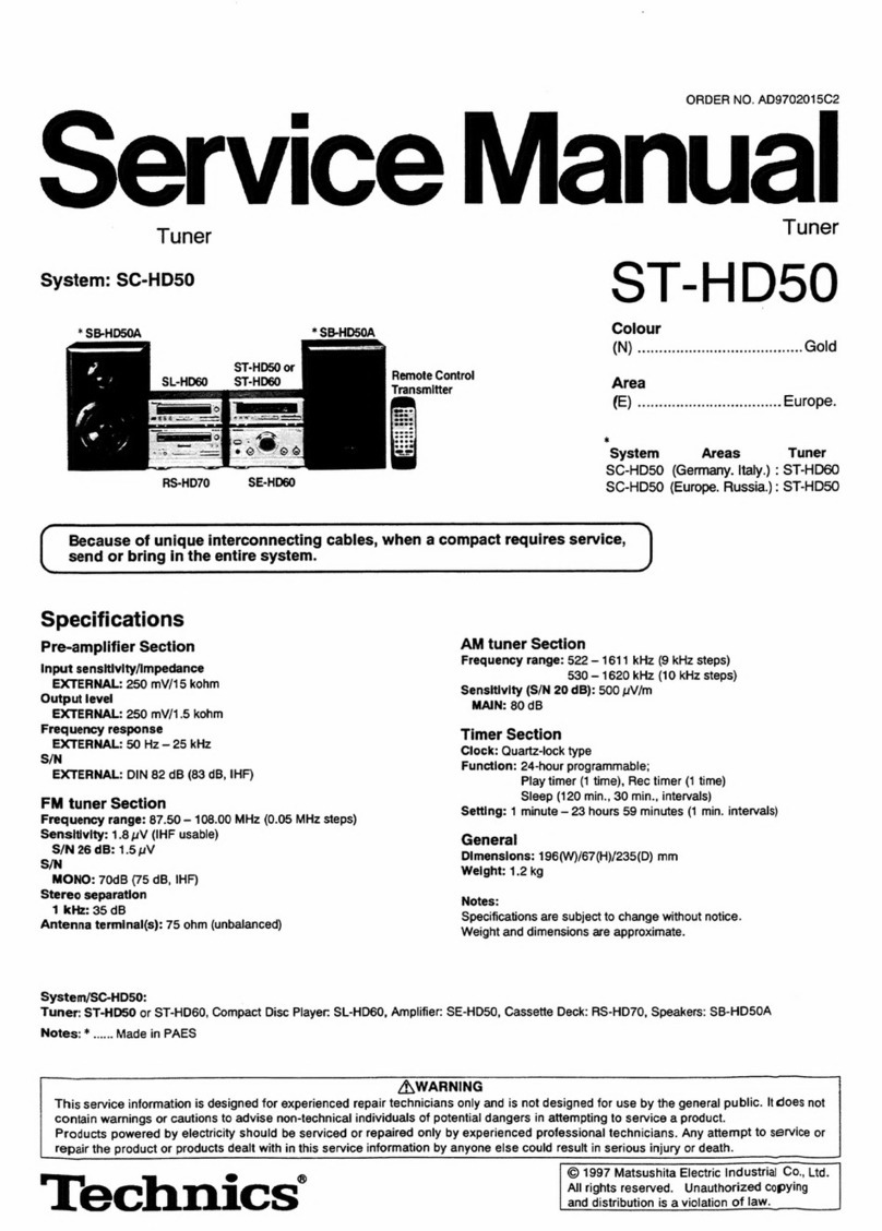
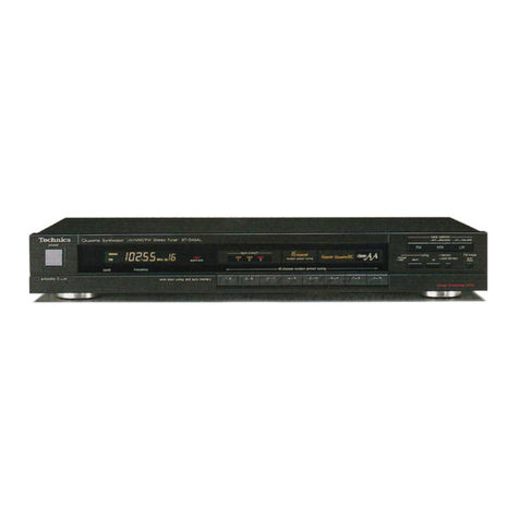
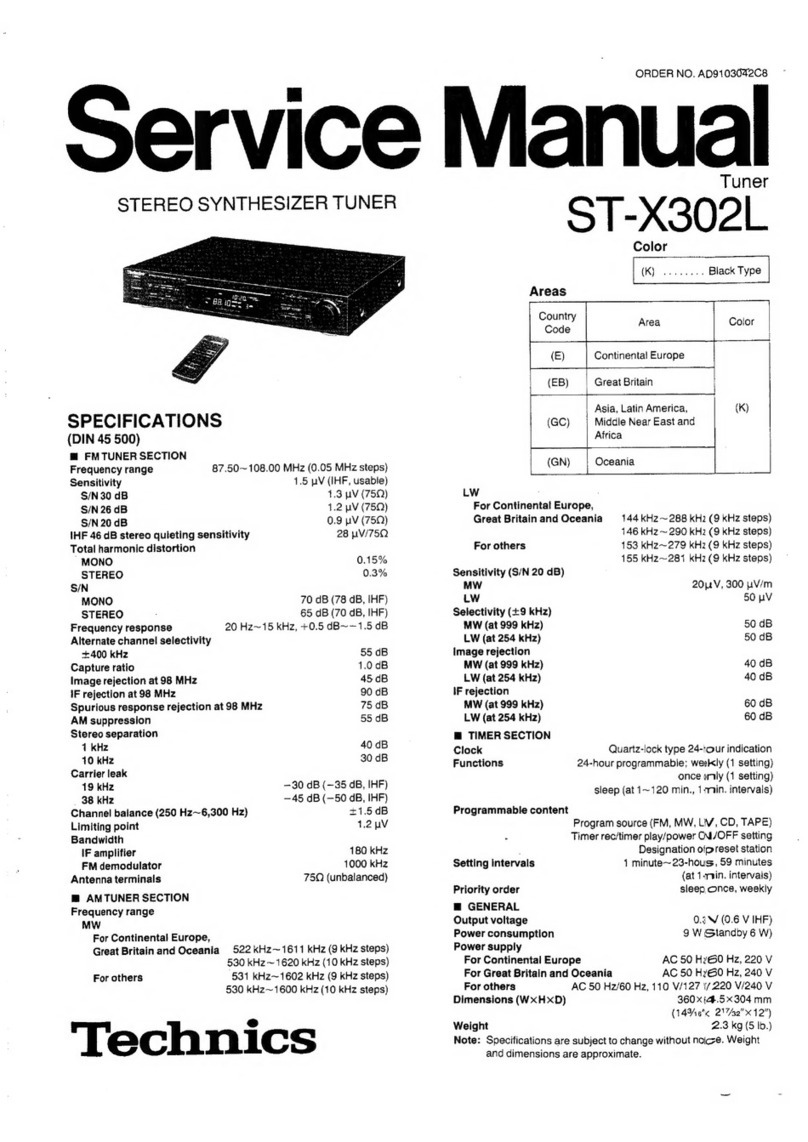
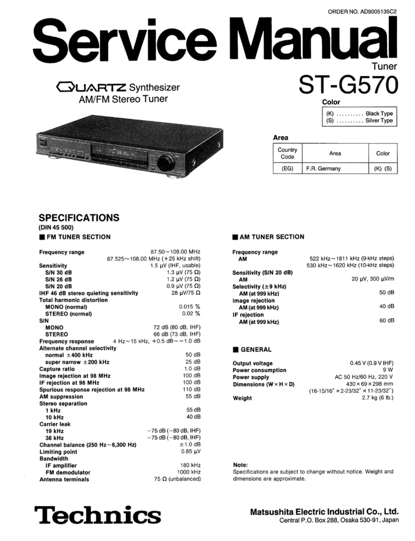
  9. Technics QUARTZ ST-X999 User manual

Technics QUARTZ ST-X999 User manual

CYUARTZ
Synthesizer
AM/FM
Stereo
Tuner
SPECIFICATIONS
(DIN
45
500)
m
FM
TUNER
SECTION
Frequency
range
Sensitivity
S/N
30
dB
S/N
26
dB
S/N
20
dB
IHF
46
dB
stereo
quieting
sensitivity
Total
harmonic
distortion
MONO
STEREO
S/N
MONO
STEREO
Frequency
response
20
Hz
~
15
kHz,
Alternate
channel
selectivity
+400
kHz
Capture
ratio
Image
rejection
at
98
MHz
IF
rejection
at
98
MHz
Spurious
response
rejection
at
98
MHz
AM
suppression
Stereo
separation
1
kHz
Carrier
leak
19
kHz
38
kHz
Channel
balance
(250
Hz
~
6,300
Hz)
Limiting
point
Bandwidth
IF
amplifier
FM
demodulator
Antenna
terminals
m
AM
TUNER
SECTION
Frequency
range
MW
530
kHz
~
1620
87.50~
108.00
MHz
(0.05
MHz-steps)
1.5
pV
(IHF,
usable)
~70
dB
(—80
dB,
IHF)
—75
dB
(—80
dB,
IHF)
Selectivity
(+
9
kHz)
MW
(at
999
kHz)
iow
aot
image
rejection
1.2
pV
(759
)
0.9
pV
(750)
MW
(at
999
kHz)
28
uV/75Q
IF
rejection
MW
(at
999
kHz)
0.15%
ee
SECTION
0.3%
70
dB
(78
dB,IHF
)
Precision
65
dB
(71
dB,IHF
)
Functions
+0.5
dB
~
-1.5
dB
70
dB
1.0dB
Programmable
content
90
dB
90
dB
90dB_
Setting
intervals
55
dB
Priority
order
40dB
&
GENERAL
Output
voltage
Power
consumption
Power
supply
+1.2dB
Dimensions
(W
x
H
x
D)
1.0
pV
.
Weight
180
kHz
1000
kHz
75Q
(unbalanced)
522
kHz
~
1611
kHz
(9
kHz-steps)
kHz
(10
kHz-steps)
ORDER
NO.
AD89051
18C2
ervice
Manual
Tuner
3
T-X999
Color
|
(K)...Black
Type
|
Area
Country
Code
Area
Color
(EG)
|
F.
R.
Germany
&
Italy
(K)
Sensitivity
(S/N
20
dB)
MW
20
pV,300
pV/m
55
dB
40
dB
60
dB
Quarz-jock
type
24-hour
indication
Within
0
sec.~
+10
sec.
monthly
(at
25°C)
24-hours
programmable
weekly
(1
setting)
once
only
(1
setting)
sleep
(at
10~60
min.
10-min.
intervals)
Program
source
(FM,
MW)
Power
ON/OFF
setting
Designation
of
preset
station
1
minute
~23
hours,59
minutes
(at
1-min.intervals)
sleep,
once,
weekly
0.5
V
(1.0
V,
IHF)
9W(clock
5W)
AC
50
Hz/60
Hz.220V
360
x
64.5
x
288
mm
(14-3/16”
x
2-17/32”
x
11-11/32”)
2.1
kg
(4.6
Ib.)
Specifications
are
subject
to
change
without
notice.
Weight
and
dimensions
are
approximate.
Technics
Matsushita
Electric
Industrial
Co.,
Ltd.
Central
P.O.
Box
288,
Osaka
530-91,
Japan
@
CONTENTS
Page
Page
ACCESSORIES.
sis
s2
Ses
seed
eee
naeneaeehesaasa
dad
2
CIRCUIT
BOARDS
AND
WIRING
CONNECTION
CONNECTIONS
2.0.0.0...
ccc
cece
eee
eet
2
DIAGRAM
So.
nasa
cetais
denied
och
eee
14~16
LOCATION
OF
CONTROLS
...............00
20
ee
eens
3
FUNCTIONS
OF
IC
TERMINALS.................0.,
17
DISASSEMBLY
INSTRUCTIONS
...............00.
4,5
DESCRIPTION
OF
FLPANEL
............2.....00.,.
18
MEASUREMENTS
AND
ADJUSTMENTS
............
6,7
RESISTORS
AND
CAPACITORS
...............
19~21
BLOCK
DIAGRAM
..........
000
e
cece
eter
teens
8,9
REPLACEMENT
PARTS
LIST
..................
21~23
SCHEMATIC
DIAGRAM
..............000
eee
ee
10~13
EXPLODED
VIEWS...
1...
eect
ee
ees
24
TERMINAL
GUIDE
OF
IC’S,
TRANSISTORS
AND
DIODES:
“eidsrevnatetedeig
cin
fa
Sis
She
owe
nas
Gs
14
m@
ACCESSORIES
Stereo
connection
cable
(SUPK2203-1)
..............
1
©3-core
flat
cable
(SWKTX930E)
.............
ccc
ve
ee
1
@FM
indoor
antenna
(SSA270M)
................-.0005
1
e@AC
power
supply
cord
(SFDACO5E03)
.................
1
@AM
loop
antenna
(SPB1162T)
...............
ee ee
eee
1
eRemote-control
transmitter
(EUR64754)
..............
1
e@AM
antenna
holders
(SMA233-1M)
..............-065
1
Batteries
(RO3)
.....
0.
cece
eee
eee
ee
2
(SMA231M)
.......
0.
cece
eee
eee
1
e@Screws
(XTB3+10AFZ)
.....
0...
cee
ccc
eens
2
™@
CONNECTIONS
7
AM
LOOP
ANT
“SWITCHED”
outlet:
This
unit
CONTROL
AMPLIFIER
eet
Stereo
connection
A
cable
(included)
AC
power
supply
cord
(Included
with
amplifier)
3-core
flat
cable
(included)
Amplifier
(option)
Ze
—
@O0OOO
PQOOOO®
Audio
equipment
rated
up
to
500W
can
be
connected.
Power
is
controlled
by
power
switch
of
this
unit.
Household
AC
outlet
2)
AC
power
supply
cord
(included)
The
configuration
of
the
AC
outlet
and
AC
power
supply
cord
differs
according
to
area.
ORDER
NO.
AD8905118C2-A
CQUARTZ
Synthesizer
MW/FM
Stereo
Tuner
ST-X999
@
Frequenzzahler
@
Drosselspule(100,H)
@
Widerstand(100kQ)
m
MESSUNGEN
UND
JUSTIERUNGEN
UKW
JUSTIERUNGEN
Einstellungen
der
Bedienelemente
und
zu
verwendende
Gerate.
@
UKW-Messender(UKW-MS)
@
Stereo-Modulator
@
Verzerrungs-Analystator
@
Elektronische
Gleichstrom-Voltmeter(EVM)
Anmerkung:
Fir
2201,
Z202,
L321
und
L322
werden
bereits
justierte
Ersatzteile
geliefert.
Die
Kerne
dieser
Teil
daher
nicht
drehen.
UKW-MONO-VERZERRUNGS-JUSTIERUNG
1.Der
Testaufbau
ist
in
der
Abbildung
gezeigft.
2.Stellen
Sie
die
Einheit
auf
“"FM(UKW)”
Betrieb.
ZUSTAND
DES
UKW-MESSENDERS
Modulation
Modulationsfrequenz
Ausgangspegel
3.Die
Radiofrequenzanzeige
und
den
Messender
auf
100.10MHz
einstellen.
4.Den
Kern
von
T201
so
justieren,
daB
die
im
Signalzustand
gemessene
Spannung
OmV
(0+20mV)
im
300mV-Bereich
betragt.
5.7202
so
justieren,
daB
der
Verzerrungsfaktor
des
linken
Kanals
minimal
wird.
6.Schritte
4
und
5
einige
Male
wiederholen.
7.Versichern
Sie
sich,
daB
die
Verzerrungsfaktoren
von
Kanal
L
und
Kanal
R
annahernd
gleich
sind
und
auf
ein
Minimum
gehaiten
sind.
Anmerkung:
Fur
die
Justierung
ist
ein
Schraubendreher
aus
Kunststoff
zu
verwenden.
MPX-SGO-JUSTIERUNG
1.Der
Testaufbau
ist
in
der
Abbildung
gezeigt.
2.Den
UKW-Bertriebsart-Wahlshalter
in
die
“on/auto”-Po-
sition
stellen.
3.Radio
und
MeBsender
auf
100.10MHz
einstellen.
4.VR301
auf
19kHz
+
30Hz
auf
der
Frequenzzahleranzeige
justieren.
@
VERWENDUNG
EINES
ALTERNATIVSYSTEMS
1.Stereosignal
vom
Mefsender
eingeben
oder
eine
Stereo-Sendung
empfangen.
2.VR301
justieren,
bis
die
Stereo-Anzeige
aufleuchtet.
Den
Arm
von
VR301
mit
Lack
sichern,
wie
in
der
Abbildung
gezeigt.
Digitaler
Frequenzmesser
“Stereo”
AUS
ZUSTAND
DES
UKW-MESSENDERS
Modulation
...
100%
Modulationsfrequenz
.........0KHz
Ausgangspegel,
“Stereo”
AUS
Stellung
“Stereo”
EIN
Stellung
(Anzeigebeleuchtung)
Einstellpunkt
des
pilotschaltkreis’
ELNSTELLUNG
DER
PHASENSPERRUNG
EINES
SCHLEIFENVERSCHIUSSES
1.Der
Anschlu8
der
Testausriistung
ist
in
der
Abbiidung
dargestellt.
2.TP903
und
TP904
Uberbriicken.
3.CT901
unter
Beobachtung
des
Frequenzzahlers
auf
524,288
kHz+10
Hz
einstellen.
4.Nach
der
Einstellung
die
Uberbriickung
zwischen
TP903
und
TP904
entfernen.
5.Den
Netzschalter ausschalten.
UKW
STEREO
KLIRRFAKTOR-JUSTIERUNG
1.Der
Testaufbau
ist
in
der
Abbildung
gezeigt.
2.Stellen
Sie
die
Einheit
auf
"FM(UKW)”
Betrieb.
3.Die
Radiofrequenzanzeige
und
den
Messender
auf
100.10MHz
einstellen.
4.L1
so
justieren,
daB
der
Verzerrungsfaktor
des
linken
Kanals
minimal
wird.
5.,Uberprifen,
daB
die
Verzerrungsfaktoren
des
linken
und
rechten
Kanals
fast
gleich
sind.
Anmerkung:
Fur
die
Justierung
ist
ein
Schraubendreher
aus
Kunststoff
zu
verwenden.
Eine
MeBsonde
hoher
Impedanz
verwenden.
Digitaier
Frequenzmesser
ZUSTAND
DES
UKW-MESSENDERS
Modulation
“L”order
“R”
Betriebsart
90%
,Pilotssigna!l
10%
Modulationsfrequenz
.........1kKHz(Pilot
19kHz)
Ausgangspegel
BEBO
UKW
ANT
—
ay’
A
8
STEREO
MOOULATOR
Abgabebetried
...
L
oder
A
Printed
in
Japan
F890502,100
TW/FF/YY
m
LOCATION
OF
CONTROLS
Tuner
section
i
Power
“STANDBY
())
/ON”
switch
(POWER
“ON/STANDBY
(!)”)
Remote-control
signal
receptor
(SENSOR)
FM
mode
selector
(FM
MODE)
Tuning
buttons
(TUNING)
Band
selectors
(BAND
SELECTOR)
Preset-tuning
buttons
(1-0)
(28
CHANNEL
RANDOM
PRESET
TUNING)
Memory
button
(MEMORY)
Timer
section
Digital
frequency
display
Quartz-lock
indicator
(QUARTZ
LOCK)
Memory
indicator
(MEMO)
Channel
display
FM
stereo
indicator
(STEREO)
FM
mode
indicators
Es
Ae
oo
&
(=| [=|
[>]
[&) fs)
SS)
6||7
F
[1]
Sleep
button
(SLEEP)
[A]
Stand-by
indicator
(STANDBY)
[2]
Cancel
button
(CANCEL)
Day
display
[3]
Stand-by
button
(STANDBY)
Timer
ON/OFF
indicator
(ON/OFF)
[4]
Read
button
(READ)
[D]
Time
display
[5]
Set
button
(SET)
[E]
Colon
indicator
[6]
Select
buttons
(SELECT)
[F]
Timer-mode
indicator
(ONCE/WEEKLY/SLEEP)
Clock
set
button
(CLOCK
SET)
*
The
operating
procedures
and
features
are
similar
to
those
for
and
of
the
ST-X990.
eRemote
control
transmitter
(EUR64754)
oO
ROPE
m
DISASSEMBLY
INSTRUCTIONS
Ref.
No.
1
Removal
of
the
cabinet
|
Procedure
|
@Remove
the
4
screws
(@~Q).
|
1
-—___-
+
Ref.No.
|
Removal
of
the
front
panel
3.
Remove
the
3
screws
(Q@~®).
2
4.
Remove
the
front
panel
in
the
direction
of
the
arrow.
|
Procedure
|
1.
Remove
the
flat
cable
(J901,
J902).
1-2
2.
Push
the
front
panel
in
the
direction
of
the
arrow
@
and
remove
the
holder
in
the
direction
of
the
arrow
@).
Removal
of
the
flat
cable
Pull
out
the
flat
cable
while
pressing
the
Flat
connector
cable
Connector
Ref.
No.
3
2.
Remove
the
3
screws
(@~®).
3.
Slightly
pull
the
front
panel
toward
you
and
remove
the
main
P.C.B.
Removal
of
the
main
P.C.B.
Procedure
|
1,
Remove
the
10
screws
(Q@~®).
133
Removal
of
the
preset
tuning
SW
P.C.B.
and
band/tuning/timer
operation
SW
P.C.B.
Band/
tuning
/
timer
operation
SW
P.C.B.
Procedure
12-4
1.
Remove
the
4
screws
(@~O).
2.
Remove
the
band/tuning/timer
operation
SW
P.C.B.
3.
Remove
the
1
screw
(@).
4.
Push
the
4
claws
and
remove
the
preset
tuning
AA
rae
SW
P.C.B.
Preset
tuning
SW
P.CB,
~~
4A)
§
-
‘
e
Ref.
No.
5
=
Procedure
Removal
of
the
remote
control
j
1.Remove
the
battery
cover
lid.
3.Insert
a
screwdriver
blade
between
the
2.
Remove
the
one
screw
(@).
upper
and
lower
covers
inside
the
battery
compartment
and
them
slowly
loosen
the
bottom
cover.
Battery
cover
lid
m@
MEASUREMENTS
AND
ADJUSTMENTS
FM
ADJUSTMENT
Control
positions
and
equipment
used
@
FM
signal
generator(FM-SG)
@
Frequency
counter
e@
Stereo
modulator
@
Choke
coil({100uH)}
@
Distortion
analyser
@
Resistor(100kQ)
@
DC
electronic
voltmeter(EVM)
Note:
For
Z201
(AM-ANT/OSC),
Z202
(AM-IFT),
L321
(L.P.F)
and
L322
(L.P.F),
they
are
supplied
as
adjusted
parts.
So,
do
not
turn
the
cores
of
the
parts.
It
is
not
necessary
to
adjust
the
AM
circuit.
FM
MONO
DISTORTION
ADJUSTMENT
FM
SIGNAL
GENERATOR
CONDITION
1.Test
equipment
connection
is
shown
in
figure.
Modulation
2.Set
the
unit
to
"FM”
mode.
Modulation
frequency
3.Set
the
radio
frequency
display
and
signal
generator
to
Output
leve!
100.10MHz.
4.Adjust
the
core
of
T201
so
that
the
voltage
measured
in
signal
mode
is
OmV(O0+20mV)
in
300mV
range.
5.Adjust
T202
so
that
the
distortion
factor
of
L-CH
is
mini-
mized.
6.Repeat
steps
4
and
5.
7.Make
sure
that
the
distortion
factors
of
L-CH
and
R-CH
are
nearly
the
same
and
minimum.
Note:
The
adjusting
screwdriver
used
should
be
made
of
resin.
MPX
VCO
ADJUSTMENT
1.Test
equipment
connection
is
shown
in
figure.
2.Set
the
unit
to
“on/auto”
position.
3.Set
the
radio
frequency
display
and
signal
genarator
to
100.10MHz.
4.Adjust
VR301
for
19kHz+30Hz
on
frequency
counter
reading.
USING
ALTERNATE
SYSTEM
1.Receive
the
stereo
broadcast.
2.Adjust
VR301
until
stereo
indicator
lights
up.
Fix
the
arm
of
VR301
as
shown
in
figure.
Frequency
counter
"*Stereo"’
OFF
FM
SIGNAL
GENERATOR
CONDITION
Modulation
one
100%
Modulation
frequency
........
OkHz
Output
level...
eee
66dB
@-®,
O-©.......
“Stereo”
OFF
position
®-®.......
“Stereo”
ON
position
(indicator
fighting)
Os
edieicvece
Adjust
point
of
pilot
circult
PLL
CLOCK
FREQUENCY
ADJUSTMENT
Use
a
high
impedance
probe.
P : :
‘
‘s
Frequency
Counter
1.Test
equipment
connection
is
shown
in
figure.
2.Short
TP903
and
TP904.
3.Adjust
CT901
for
524.288kHz+10Hz
on
frequency
counter
reading.
4.
After
the
adjustment,
open
up
the
shorting
between
TP903
and
TP904.
5.
Turn
off
the
power
switch.
kHz
a
TP901
0
Ee?
FM
ANT
(750)
TP902
(GND)
FM
STEREO
DISTORTION
ADJUSTMENT
1.Test
equipment
connection
is
shown
in
figure.
2.Set
the
unit
to
"FM”
mode.
3.Set
the
radio
frequency
display
and
signal
generator
to
100.10MHz.
4.Adjuste
L1
so
that
the
distortion
factor
of
L-CH
is
minimized.
5.Make
sure
that
the
distortion
factors
of
L-CH
and
R-CH
are
nearly
the
same
and
minimum.
Modulation
Output
level
Note:
The
adjusting
screwdriver
used
should
be
made
of
resin.
eADJUSTMENT
POINTS
AMLOOP
ANT
FMANT
75Q
OUTPUT
|
(100.0
MHz)
fa]
FM
FRONT-END
PACK
FM
offset
FM
MONO
distortion
PLL
Clock
FM
MPX
VCO
(19
KHz
output)
]
~S
@|
PLL
Clock
GND
{C901
FM
MPX
VCO
(19
kHz)
Modulation
frequency
FM
offset
(—)
adj
FM
offset
(+)
adj
FM
SIGNAL
GENERATOR
CONDITION
“L”mode
or
“R”mode
90%,
Pilot
10%
1kHz(Pilot
19kHz)
66d
FM
ANT
AM
ANT
AM
Signal
Zi
FM
FRONT
END
faa
ae
m@
BLOCK
DIAGRAM
CF201
CF
202
8
sf
FM
OSC
Q201,202
r
i
a
wi
|
©
eat)
Qld!
|
Qi02
FM/AM
Loop
filter
aa
FM
MONO
DISTORTION
adj.
See
°
¢
T201,202
“iy
AN7273A
det,
coil
FM/AM
IF
AMP.
DET,
16
I7
de
4
med
AMP
O==0
7
L
C201
Q205
Signal
receive
detector
X10
(AM)
Q207~209
(72MHz)
FM/AM
=
Power
supply
a
Y
selector
=
ry
—
SDC
INT
©
PLL
FREQUENCY
RESET
©
SYNTHESIZER
DgIU
ogi!
p33}
0912
:
BA
Ko
;
D913
py
re
PO3Q
m
Ty
T
q
901
$902 $903
$904
|
goo
(1)
(So)
3
(2)
ie
re
(3)
$s
4
(4)
D7S5IQSHGF7OI
Hf
«se
IC
901
$905
$906
$907
$908
p
OO
(5)
re
8
(6)
pore
m
$29
8
af
MICRO
COMPUTER
OWER
©
_
KS3
$909
$910
s9l2
eo
5
(9)
a
(0)
re
f
(MEMORY)
B
|
Seana
4
S9I7
$918
$914
$921
bys
rare:
(TIME
ato
(TIME
Sta
(CLOCK
aS
re
Vien
T°
9
Rean
f°
f
ser)
f°
2
(SLEEP)
.
2
2s
x2
6
sgig9
$920
$928
¢O
9
(STANDBY#-O
9
(CANCEL)
12
$
(POWER)
|
i
~
id
ise
$9i5
s9l6
$924
$923
a
bane
2
(TIME
A
)¢-0
(TIME
7
“0
(UP
(DOWN
ne
Zi
tuniney
f°
P
TUNING)
.
8b
ks5
$926
$925
$922
LOO
(AM)
220
(FM)
2
(MODE)
id
vary
L
aaa:
naa
cs
Vss
$0
~
$15
---------T0~T7
VOOaD
:
—
eee
ee
i
ee
ee
Oo
——
KEY
MATRIX
ons
Hy
e
a
FL9OI
DISPLAY
—8—
mode
90%,
FM
ANT
ZI
FM
FRONT
END
ft,
ose
-i-s
ey
ee
GY
7
m@
BLOCK
DIAGRAM
CF201
CF
202
8
FM
MONO
DISTORTION
adj
ea
cee
a
Oo
O
T201,202
it
FM
det,
coil
2
c
9
16
Ji7
jh
O
O=-0=-O
(1)
4
AN7273A
FM/AM
IF
AMP,
DET,
AF
AMP
AN?7470
FM
MPX
O
_——
Om
ee
eer
rn
csr
sr
nn
nr
snr
canna
cnn
acre
rcs
een
ene
ee
ee
ee
;
jin
9201,202
r
L
|
En
|
|:
|
RF
6
FM
|
=o
Mix
.
YrfeM
amy
bel
FM
|_|
Mating
|
6
O)
Reh
dp
TA
IF
amp}
det
level
det
|
Ja
@302
|
g
FM
OSC
|
7
SY
|
|
7
Z202
|
:
ate
etic
iq!
13
X
ae
OUTPUT
|
|
|
fl
Y
HF
van
R313,
ant
1
aeariet)
cieaa
LT
tin
ty
L_
eT
b=
;
ii
Cet
°
y
meter
|
Stereo/
~O)
Lch
i
mono
Qlol
|
Q102
eee
aeereee
4
|
]
selector
|
SN
Forcible
a30i(
:
|
=|
3)
Loop
filter
a]
z
VCO
stop
3
AM
AM
AM
I
|
L
|
|
C
elneantimtiematen
©
padkemtemn
Sorukenten
Somniieten
©
cite
|
2
5
18
6
0
15
9303,
aged
rte
eager
=
4
A
at
304
1
¢8)
|
©
d
eee
cece
A
+>
'
AM
OSC
Coil
piv
:
Zee’
AM
OSC
|
+
VR301
TP3010
_?
T
MPX,VCO
adj
MPX
VCO
odj
|
(2)
!
-——
G8)
ie
ee
(AM)
oi
D204
Se
He
205
(1)|
CONTROL
OUT
1
GenrRoe
(2)}
REMOTE
CONTROL
ae
ine
AMPLIFIER)
(2)
G)
+8
OUTPUT
(AM)
ig
G8)
D
(Teme)
Q210
o
20
1e02
Saar
z90!
oO
oO
FM/AM
8
=
Remote
Power
supply
SS
B
o
Vv
Remote
control
3
I
2
14
i
selector
a
receiver
4
XOUT
Xin
POI
FM
wl
FH
!
4
4
!
1
|
AM
no
(2)
Note
Vss
cE GL
pata
J
3
60
53
4
pe
54
Pe
aa
oe
5
=
—
=
SS
=
wor
a
ee
6
34
f5
I
FM
STEREO
MONO
MUTE
80
FM
soc
|
—=
FM
Signal
soc
o00C>
FM
OSC
|
LM7OO!I
8h
oars
ine
be
!
|
{C101
hep
is
|
mm
AM
Signa!
|
PLL
FREQUENCY
é
Reser
ae
|
sta
am
osc
|
SYNTHESIZER
ce
L
0910
14
O9I1
7
15
a
p33
O28
o
KI
ogi2
ea
64
x
t
t
0913
Bt
és
17
K3
PO3
Q
if
$901
soo2
|
5903.
|
‘so0a
|
|
|
2
oO
0
(1)
i
(2)
te)
$
(3)
gs
(4)
:
D7SISHGF7OI
|
ac
Sa
Hp
x82
fic
901]
O203
$905
$906
$907
s908
poweR
{2
yo
Oo
(5)
fo
(6)
(7)
te)
(8)
MICRO
COMPUTER
os
124
sy
D909
$909
$910
$912
I
+6
(9)
0
(0)
$3
9
(MEMORY)
bs
I
Q701.702,
as
S9l7
S918
S34
|
$921
|
D701
~
704
T701
oS
(TIME
05
(TIME
too
(CLOCK
Rio}
EP)
23
SET)
READ)
fg.
set)
Piste
“
2h
sy
x2
t—
;
2
a
Ct
AC
IN
1
=S9l9
Tue
$920
1
$928
|
=
x90!
Rectifier
t©
9
(sTanosy
PICANCEL)
D
(POWER)
|
i
(4.194304
MHz)
and
~
24
39
24
S9I5
S916
lneet
10233
a!
de
J,
regulator
N
Po
7
UTIME
A
f-0
0
(TIME
Y
)-9
TUNING)
[©
TUNING)
8
I
$926
$922
~
see
$925
458__Ge)
ee
ed
pane
Sey
oTE_tamy
Dem
S"D_
Moe)
4
Woo
8)
(2)
RLY7O1
Dee
+
—
cee
vss
$0~
S15
---------
T0~T7
TORS
:
of
--
--—
-s-oo
--
D710~713
SQ
oa
KEY
MATRIX
-
3
-
=
ow
A
+
i
AC
OUTLET
|
Q906
(SWITCHED)
RELAY
DRIVE
FL9OI
DISPLAY
|
et
T
|
Se
ee
—~8—
—~9
ST-X999
1
2
MAIN
CIRCUIT
PopSet
SSS
7
A
JKION-1
FM
ANT
750.
FM
signal
i
|
F
|
AM
signal
\
I
JKION-2
AM
ANT
®)
!
B
JKIOI-3
L203
Ip
a
ena
LOOP
ANT
ve
y
(AM)
O)
Cil2
0.001
at
ye
58
ye:
2SK2668
FM
MIXER
Tt
201,202
2SC2787LTA
FM
IF
AMP
(Clo
LM7OOI
PLL
FREQUENCY
SYNTHESIZER
R902
2.2K
RIOS C108
560
25V47
S22kH2—1611
KHZ
;
OO
%
(FM)
-
esyv
sipleae
oe
|
1
'
eth
ae
ff
87
SMHz
—=108
OkHz
C106
20.01
RIO4
IK
Q101,102
2SC2603EFGTA
FM/AM
LOOP
FILTER
ST-X999
ST-X999
10
FM
+B
LINE
9208,
209
regs
2SA933SQRSTA
AM
OSC
POWER
SUPPLY
(FM/AM)
4
0207
1SS254TA
AM
+8
LINE
0204
ISS254TA
a
35
3
=
0914,
915
<=
MAISOLF
D915
(ORNG)
4-5
0914
-*t-4
0917
4-5
0910
+913
917,919
'SS254TA
lav
(14.3V)
14.5v
(av)
Q207
R221
100K
2SCI740SQSTA
POWER
SUPPLY
(FM/AM)
R250
560
1c201
AN7273A
4.7
e210
r
2SC1740SQSTA
TA
oH;
ue
9
040
040
0
$901
|
[s902
|
[s903
75)
6)
7)
ae
0
0890
O00
0
s905
|
|s906
|
['s907
7)
@
(MEMORY
)
a
ot
——
$909
°o
O o
S910
sal2
FEW
switcy
circuit
(TIMER
(TIMER
(CLOCK
SET)
READ)
SET)
(SLEEP)
a
—
1
47V)
R913
150K
R9I5
150K
aN
R96
|
R914
150K
R937
56K
WV
A090
O40
840
OY
S9I7
S9i8
S914
$92i
(STANDBY)
CANCEL!
R936
5.6K
a
(Rye
o
O-@
O@9
O
Ysoi9
$920
$928
(
CTA)
ISELECTY)
SELE
TV:
°
O
S915
|
[S916
AWN
R935
5.6K
AM
4
oH
$924
$923
t
AM)
(MODE)
4.
pas
eae
iFM!
ot
°
see
$925
REMOTE
SENSOR/
2301
K68
SWITCH
CIRCUIT
ewe
cont’
oe
$922
66026646
©,
BUFFER
AMP
83
(AM
OSC)
a
ge
9901
=
2SC1I74O0SQSTA
SWITCHING
2SA933SQRSTA
R2is
47K
(REMOTE
CONT)
MUTINGSCORT
_4
a
5
i
ge
@205
s
{
Cae
Fa
is
2SC1740SQSTA
x
|
|S
R928
SIGNAL
RECEIVE
mS
ley
DETECTOR
ay
le
a
fy
ea
=
=
ia
|
38
Bee
RBS
18825a7
AN
|
990!
ae
Bra
58
RS
:
~
36
|
s
=
Q905
“
2
OV
$a7v
I4.6v
1a6v
fov
3
BV
OV
54v
me
a
(9-0
+
-O--O
0)
-0-O-©)-0-©-O-O-
OOO)
etre
Nahe
aS
aS
Sav
R949
g
4
~
|
R920
10k
KS6
KSS
K3
K2
KI
KO
KS4
KS3
KS2
KSI
KSO
P62
CL
DATA
PO3
SD
STEREO
INT
NC
as05
fA
TET
-
Nyy
370K
2.9
@9
ks?
ce
NC
Vt
ae0d\
2SCI740SQSTA
e906
i
oN
5
G84
mney
POWER
FAILURE
2SC!740SQSTA
——(2i)
kse
|
a
No
Signa!
"H"
RESET
@e=
es
3
a
DETECTION
RELAY
DRIVE
2
\
Received
Signai"L"
.
©
=
(GND)
ve
Key:
Penh
Sil,
Key
Scan
Sian
Ne
ATV
rower
OL
gsc
8
x
Bs
He
|
3
x90!
0
:
L~
ov
PLL
clock
222%
=
8
152
4.194304
MHz
or
2V/
msec
div.
Li
0
-|-F
|
frequency
g
ov
=
V2
_
x2
2V/Imsec
div.
PCL
GI}—0
Le
(r)os02
$
C712
RO4I
col?
E55
Se
TPO!
Ov
©
ov
5.5V0.047
330
5.6P
2
mS
<
=
H
=
x!
ibe
MONO
0)
s
me
cra
ae
we
aty
8.
rs
OV,
(
)
e906
6v
1000
e730!
PSS
Hiecrth
cee
sil
e
ov
g
‘3
S
cit
Mae
Wl
pon
vere
‘cai
For
cible
mone.
mode
Fmsoc
G9)
Z
3
70.01
“8
G6)
voo
07519HGF701
voo
6+
d
MICRO
COMPUTER
e902
0902
s7
6
2SCI740SQSTA
MAIGSTA
SWITCHING
:
sé
é
ove
4
47V,
Segument
Signal
Grid
Signat
4.
6V
(OV)
$3--
as
monn
m4
4
i
pa!
weds
G79!
|_|
Sra
WB
ei
images
5V
2SC3940A0ST/
GO
s4
bhi
U
Lis
oy
~30v
hice
50c
64)
—_
5
9903
REGULATOR
|_|
20V/0.5msec.
div
20v/
0
5msec
div
Mating
©
28C2787LTA
Ss
|__]
3
©
VOLTAGE
as
S
DETECTION
is
~
ge
!
1
i“
SO
SIS
Sl4
Si3
$i2
Stt
$io
$9
ss T7
Té
Q903
(5
av)
I
R715
100
Q702
Lt
tos
[8
hs
2SCI685RST
28
REGULATOR
Papeed
3
|s 3} |e
138
L
8
“|
Ve)
2
ot
HOR
8}
18)
Le
3}
13
Ls
7
Cd
a
.
oe
=
B—-B)-@9-
2).
299
O_O
(9
_O-9
1-0)
-O#-+O)$
-01-©-O$-O#-D-O-O
8
z
FL9O!
(SADFV273G)
FL
DISPLAY
REMOTE
CONT.
RECEIVER
—~10—
-W-
ST-X999
ST-X999
10 12 13 14
'SC2787LTA
L901
100p
LM70O[
SYNTHESIZER
AF
signal
R250
{HL
ina
=
eae
eae
eee
Ie
=aante
5.6K
0909
1SS254TA
KO
KS4
KS3
KS2
KSI
ZK
R320
7
KS6
KS5S
K3
KS
Key
Return
Signal
8
OV
x2
x
SAN
[isve-e
Vss
Ps
Wl
\oaverp
D7519HGF7OI
MICRO
COMPUTER
20v/0.5msec.
div
—
|
=
~~~)
in
eae
KSO
P62
Grid
Signa!
ai.
Tee
-wWvV
20V/0.Smsec.
div
2SC2787LTA
cgi2
0.01
K
MA
een,
7
SO
SIS
sia
Si3
Sie
iS)
>|
g
® ®
FL9O!
(SAOFV273G)
1S
T4
13
2
35V100
C928
100P
100
¢305_
R305
L32I
ico
N83
eK
te
Ae
EM
SERENE
0208,
209
a
aroe-L5o
Y
‘
2,
SORSTA
PLL
FREGUEKCY
2SA933SQRSTA
1201
7
1
eSD
ia
POWER
SUPPLY
AN7273A
H
Q
R325
JK301
(FM/AM)
FM/AM
IF
AMP!
Rao
cz20
3
fy
ey
See
ee
AWN
Loch
DET,
AF
AMP
Tok
AB¥ID
AV
;
sensi
c
ew
£220
ay
ayy
4
CH
WK
414
3V
(oy)
©
esoe
i}
Nosy
:
¢
R306
i
F
35V3.
Ane
CP
ba
Sele
OUTPUT
i
Q207,
1av
8
{14.3V)
=
ic201
14.5V
8
PEP
IVS
TSE
Beenie
ee
ORT
PET
av)
ie
R
ch
(54)
(2——(1)—(10)
5
By
IV
2
a!
(BMT
SVITUSVT
oy)
to
el
av)
Z|
9207
88
a200[8T
|
wey
R233 C225
$
2SCI740SQSTA
Soe
xe
60x
_KiaP
2k
POWER
SUPPLY
$8]
Le
bSey
[os]
s
y
«@
By
IFM/AM)
FM
offset
am
roe}
L2
Le
xl
AM
+B
LINE
of
8
voltage
(Omv)
1K
|
STR
oss
Van
Zs
o
rs
of
ao
=
“MPX
VCO
adj
Q303
2SA933SQRSTA
ean
MUTING
CONT.
Q210
z
2SCI740SQSTA
Ft
_
BUFFER
AMP
&
(AM
OSC)
o2v
ore
(OV)
2°S
ges
/
2
anv
R213
aX
~S\
100K
%
Q205
CY
2SCI740SQSTA
Osa
ov
4
28
2SA933SQRSTA
ReIesamK
TSS
(REMOTE
CONT)
MUTING
CONT
3
©
=
gx
0205
se
se
ae
2SCI740SQSTA
x|
|e
SIGNAL
RECEIVE
Jk901
Ss
|e
DETECTOR
FS
R955
IK
S
z
WA
(1)
|
controw
out
5
5
954
1K
CONTROL
S58
RES
WN
(2)
REMOTE
CONTROL
OUTT
(To
AMPLIFIER)
Boa
RS
0990
MA700ATA
L902
100pH
“=
-
Vf
~~.
+B
OUT
x
=
9905
a
‘
2SA933SQRSTA
54v
¥
$0d
sav
R949
ge
CL
DATA
PO3
8D
STERE
gee
“PY ARK
£804
Sor
-
:
CH
2SCI740SQSTA
0906
C)
t
34
a904
Dey
POWER
FAILURE
2SC!
740SQSTA
se,
No
Signal
*H”
a
g
2
DETECTION
RELAY
DRIVE
Received
Signal"L"
z
cols
tie
=
H=47V
ss48
%
[es
Lov
oree
Toy
a
°
was
a
3
os
A
rvy7o1
°
<
Coa
5
=
Ce
Lg
a
eenaaiea:
Fed
=v
os
H
189.
&
2
a8
bISOT
AF2
7254
&
a
d
o_O
x
oa
ee
;
4
go
JK701
2SCI740SQSTA
-
_AtTON
Awol
;
14
7V
AC
220
47V
5
(50/60H2)
ia
os
70!
35
x8
$8
gs
“
SST
701
<8
=z
2SC3940AQSTA
5
33
REGULATOR
AC
OUTLET
(SWITCHED)
E
54v)
Q702
a
2SCIGB5RST
0702
REGULATOR
G
a
230.2V
me
C732
0.01
o710,711
ISS254TA
RTIT
—~12—
16 17
18
2
cy
|
SCHEMATIC
DIAGRAM
(Parts
list
on
page
19~22)
(This
schematic
diagram
may
be
modified
at
any
time
with
the
development
eRemote
control
unit
of
new
technology.)
‘
Note
1:
|
2')—(24)
b
6
ne
ar"
=
ov
2$901~S910__:
Preset
tuning
switches.
Note
2:
oF
=
$901:
CH1,
$902:
CH2,
S903:
CH3,
S904:
CH4,
SUseot
Goramiediltereinipelrs
29)
Chattering
ee
ae
nate
ra
Sao
CHE
Ses:
SH
The
ceramic
filters
(CF201,
CF202)
for
FM-IF
circuit
are
available
in
P|
tf
|
he
eae
he
simuhaneous
°S912
‘
Momovevicn.
three
ranks.
For
this
circuit,
be
sure
to
use
the
ceramics
of
the
(9)
push
ene
;
Luin
same
rank
in
a
pair.
O
O
S914
:
Clock
set
switch.
a
,
:
ee
ee
=
©S915~S921__:
Timer
operation
switches.
At
repairing
and
replacement,
pay
close
attention
to
the
diodes
ow
i
27
ie
3
7
=
$915:
SELECT(A),
$916:
SELECT(¥)
(D915,
D914)
for
use
as
different
diodes
must
be
used
depending
on
al al
a
a
acc
«es
$917:
SET,
$918:
READ,
S919:
STANDBY
each
rank
of
the
ceramic
filters.
oe
2h 70
he
hie
GY
S|
|shitt
resiser
$920:
CANCEL,
S921:
SLEEP
;
ies
mS
ToS
PS
|
oo
ee
A
6
©$922
:
FM
mode
selector
switch.
COlSeMAarRInG:::
res
is]
=
‘es
S$923,$924
:
Tuning
switches.
(Red,
Black
or
White)
Ff
|
I
ie
ned
2
3
$923:
DOWN,
S924:
UP
46
30
2
(5)
a
Pulse
5<z@
@$925,S926
:
Band
selector
switches.
4
eae
isc:
hs
fy
a
3
|
|
generation
BP
$925:
FM,
S926:
MW
SFE
RANK
D915
Ean
-
. :
(14)
a
©S928
:
Power
switch.
40.7MHz
(Color)
FREQUENCY
Lf
oN
e
we
ewe
¢
Indicated
voltage
values
are
the
standard
values
for
the
unit
|
Orange
|
O
|
x
|
10.72MHz
|
(3)
Lox
P
measured
by
the
DC
electronic
circuit
tester
(high-impedance)
with
10.70MH
ae
@3)
A)
the
chassis
taken
as
standard.
Therefore,
there
may
exist
some
fread
|
x
|
x
|
t0.70MHe
|
(5)
ieee
errors
in
the
voltage
values,
depending
on
the
internal
impedance
ewe
=
|
x
|
|
10.67
MHz
fe
of
the
DC
circuit
tester.
(
):
AM
voltage
©)
Zs
.
Positive
voltage
lines
AF
signal
lines
Note:
©
mark:
Diode
is
used.
Je
$
Qi
od
LI
100uH
acco
FM
OSC
<=>
FM
signal
x
mark:
Diode
is
not
used.
Fes
=
paki
anna
AM
OSC
mma
AM
signal
Osi
<1H-O)
*
Important
safety
notice
;
q
ei
ee
Components
identified
by
4,
mark
have
special
characteristics
*
Caution!
(9)
5
xt
important
for
safety.
When
replacing
any
of
these
components,
{C
and
LSI
are
sensitive
to
static
electricity.
do
s
2
0
use
only
manufacturer's
specified
parts.
Secondary
trouble
can
be
prevented
by
taking
care
during
repair.
a
°
of
sg
%*
Cover
the
parts
boxes
made
of
plastics
with
aluminum
coil.
E
as
i
*
Ground
the
soldering
iron.
F
*
Put
a
conductive
mat
on
the
work
table.
Or
ICl
+
Do
not
touch
the
legs
of
IC
or
LSI
with
the
fingers
directly.
M5046
7-Ol18FP
(
CONTROLLER
©
Remote
control
data
code
Head
Custom
Inversion
Inversion
pulse
code
Data
code
Custom
code
Data
code
Error
Check
Ger
te
NEN
39.24ms
m@
TERMINAL
GUIDE
OF
IC’S,
TRANSISTORS
AND
DIODES
lean
*Data
“0”
«Data
"1"
msle—
ay
a
|
Autorecmute
|
_—_oro01_—|—
coors
Deck
play
<
01001
ru7oo1
|
16F|
2SC3940A-Q
<>
2SC2787L
2SC1685RST
Fanzaraa_[18Fin
|__Function
__|
Customcode
|
_Datacode_|
01001
01001
010000
01001
CD.
skip/search
01100
000010
SeCea
MA165,
MA150LF
01001
010100
Pauses]
«001
000110
oe
osscan
Poi
ze00
MA700A,
1SS254
se
NP
IReoAA
Power
ON/OFF
01001
100000
01001
011000
2SD1450RS
MA4150M_
CD
play/pause
01100
001010
01001
010001
ES
pA
ae
MA4330L
Deck
play
>
001010
CD-skip/search
;
ese
ee
: ;
:
E
LA
a
K
A‘
Cathode
e
a
MA4100M
c
B
Ca
o——_4q—_©
A
|
Tuner6
Deck
>>
e
010101
01001
011001
000100
[Key
No.
|
Tuner
6
53
|
62
|eaPreset
|
oro
t10010__
[Key
No.
|
|
6
|
|
20
|
a
es
Ey
|
a
are
available
in
amics
of
the
»
the
diodes
ending
on
CENTER
FREQUENCY
10.72
MHz
10.70
MHz
10.67
MHz
ring
repair.
lum
coil.
directly.
1
2 3 4
5
6
@
CIRCUIT
BOARDS
AND
WIRING
CONNECTION
DIAGRAM
earns
ist
on
pages
19~22)
"FM
ANT
|
AM
ANT
"AM
|
[CONTROL
|
+
OUTPUT
CAC
IN
MAIN
PC.B.
(_f75a)
|
LOOP
ANT
(AMPLIFIERS
)
tachi
ean
(AC
220V
50
/60Hz
)
i
i
I
a
-
RJBOO77BA
CMK—-1
40SX
A
Re
A
|ddAS
YsaMOd
FM
offset
Vol
tage(OmV)
—~
=
\QkHz
output
(GND)
PLL
clock
frequency
adj.
—15—
C
REMOTE
SENSOR
/
SWITCH
PC.B.
SENSOR
1
(AC
OUTLET
|
(
SWITCHED)
SWITCH
PC.B.
LFM_MODE
|
-|
28CHANNEL
RANDOM
|
[a
PRESET
TUNING
peu,
—~16—
|
TIMER
OPERATION
}
AND
S
TOR
p18
DO
SELEC
eRemote
control
unit
em)
L
|
(hm)
(
Bm
STOP)
i+
Camm,
7,
(mSTOP)
REC
MUTE)
Gams
(4
——PLay——>}
=i
m@
FUNCTIONS
OF
IC
TERMINALS
e1C901
(D7519HGF701)
MICRO
COMPUTER
Function
Remote-control
input
Leading
edge
Stereo
input
Active
Low
4
Po2
sp
Station
detector
input
Active
Low
4
5
P03
Voltage
detector
input
Active
High
6
P60
so
Serial
data
output
P61
SCK
|
Serial
clock
output
Power
failure
detection
.
Pee
Active
Low
9
P63
_|KSO,
CE|
Key
soutce
output
and
CE
for
serial
transfer
hee
10
on
=
Key
source
output
Active
High
13
P53
KS4
Key
return
signal
input
Active
High
Key
source
output
Active
High
Non-Connection
Connected
to
non-connection
Vss
22
|
EVENT
Crystal
oscillator
4.19
MHz
GND
terminal
Power
terminal
5
V+10%
Segment
output
for
FIP
High
withstand
voltage
output
terminal
34
So
so
Segment
output
for
FIP
High
withstand
voltage
output
terminal
—17-—
ST-X999
BATT.
3V
D
fon)
Pin
|
Terminal
No.
Name
43
7
T7
uy
t
50
To
TO
51
|
VLOAD
|
VLOAD
52
VPRE
53
P30
MUTE
54
P31
55
P32
FM
57
INT1
INT1
58
Voo
Voo
59
P20
FMSDC
60
P2i
MONO
61
P22
PCL
P23.
|POWER
RESET
|
RESET
VPRE
|
Power
aupply
for
pre-driver
Digit
output
for
FIP
High
withstand
voltage
output
terminal
Pull-down
resistance
common
terminal
for
FIP
-30V
Muting
output
Active
Low
DTS
selective
output
FM
selective
output
High...-M
Low...AM
HALT
mode
output
Active
High
HALT
mode
(backup)
reset
Connected
in
parallel
to
P62
power
failure
detector
terminal
Power
terminal
(same
as
pin
@)
FM
simultaneous
SD
circuit
control
output
(only
auto
tuning
and
auto
scan
memory)
Active
High
FM
forced
monaural
output
High...Forced
MONO
Low...AUTO
Measuring
terminal
for
internal
system
clock
to
count
fx
767%
Power
output
High...ON
Low...OFF
Reset
terminal
High
with
timer
power
ON
HIGH
Low
with
timer
power
OFF—
LOW
Active
High
SEE)
m
DESCRIPTION
OF
FL
PANEL
eGRID
ASSIGNMENT
8G
S6
S14
S12.
$13
STANDBY
SUN
MON
THU
S4ONCE
stoTUE
FRIs1
WEEKLY
SLEEP
1
|
‘QUARTZ
LOCK
2kHz
MEMO*4
MHz
Gh.
$4
S$2
MWAM
LW
carM
|
ePIN
CONNECTION
om
FETSTSTSICIEIeLe
21
Be
aH
£738]
49
20/2
51
Ez
Pad
EE
EE
6151413
G|G|G|G
PIF
8[7
LIN|NIN|IN|NIN|N{S|S|S{S{S[S{S{S|S8/S/S|S{SIS
N{FIE
comvmenon
HH]
TID
|P
6
a]
8]
falc]
a|e
|
]e]e[P]e]r|
[s/s]
s]s|als]o]s|s
folie]
9
[>]
e]
|
e
ANODE
CONNECTION
ee
es
eee
ea
2e
MHz
iS]
o
iS)
o
a
ec!
>
Zz
co
lew]
re
iva
ct
=
ies]
ro)
NO
pp
Qa
_
[om
_
mie
|
eS
_
_
_ _
a
o
ro
a
ele
a
Lone)
G
re
oq
aa
—
ine)
_
_
_
o
1
°
—
~
_
p
2a,d,e,g
—18—
wR
Notes:
*
im
Col
ma
Numbering
S
Example:
ERD
2
Type
Wat
(1/
ERX
Type
Watt
(2'
Numbering
S
Example:
ECKD
1
Type
Volt
(5q
ECEA
5
Type
Volt
(5q
@
Capacity
va
otherwise,
f
@
Resistance
otherwise,
JTO
JNO
{EO
[oral
S|
m
RESISTORS
AND
CAPACITORS
Notes
:
*
Important
safety
notice
:
ST-X999
Components
identified
by
A\
mark
have
special
characteristics
important
for
safety.
When
replacing
any
of
these
components
use
only
manufacturer’s
specified
parts.
Numbering
System
For
Resistors
Example:
ERD
25
F
J
102
Type
Wattage
Shape
Tolerance
Value
(1/4W)
(1KQ)
ERX
2
AN
J
471
Type
Wattage
Shape
Tolerance
Value
(2W)
(470Q)
Numbering
System
For
Capacitors
Example:
ECKD
4H
102
Z
F
Type
Voltage
Value
Tolerance
Unique
(50V)
(0.001
NF)
ECEA
50
M
330
Type
Voltage
Characteristics
Value
(50V)
(33pF)
@
Capacity
values
are
in
microtarads
(UF)
unless
specified
otherwise,
P=
Pico-farads
(pF)
F=Farads
(F).
@
Resistance
values
are
in
ohms
(Q),
unless
specified
otherwise,
1K
=
1,000,
1M=
1,000kQ
Part Name
&
Description
ERD
ERG
ERQ
ERX
ERD
ERO
ERC
ERF
ERM
RRJ
:
Carbon
:
Meta!
Oxide
:
Fuse
Type
Metal
:
Metal
Film
L
:
Carbon
(chip)
K
:
Metal
Film
(chip)
:
Solid
:
Incombustible
Box-Shaped
:
Wire-Wound
:
Chip
Resistor
:
Chip
Resistor
10:
1/8W
14:
1/4W
1A:
1W
$2:
1/4W
2F
:
1/4W
2A:
2W
Resistor
Type
Wattage
12:
1/2W
25:
V/4W
18:
1/8W
S1:1/2W
50:
1/2W
3A:
3W
8G
:
1/8W
Capacitor
Type
Voltage
:
Electrolytic
:
Ceramic
:
Ceramic
Capacitor
:
Polyester
:
Polypropylene
:
Ceramic
Non
Polar
Electrolytic
:
Ceramic
(Chip
Type)
:
Ceramic
(Chip
Type)
:
Semiconductor
:
Liquid
electrolyte
double
layer
capacitor
ERDS2TJ104T
OJ:
6.3V
10
:
16V
1H
:
50V
50:
50V
2H
:
500V
1:
100V
KC
:
400V
AC
KC
:
125V
AC
(UL)
Part
Name
&
Description
C.RESISTOR
=
-1/4W
100K
K:
£10%
M:
£20%
2:
+
80
%
-20
:£5%
:
£2%
>
£1%
:
£0.25pF
:
tO.5pF
Remarks
RESISTORS
TERDS2TJIO2T
C.
RESISTOR
1/4W
1K
ST-X999
ERDS2TJ102T
Part
Name
&
Description
C.
RESISTOR
—1/4W
1K
ECBTIH102KBS
|C.
CAPACITOR
Part Name
&
Description
o0V
1000P
Remarks
ERDS2TJ1027
C.RESISTOR
1/4¥
IK
~
TRCBSIHI81KBY
|C.
CAPACITOR
o0V
180P
ERDS2TJ183T
C.RESISTOR
1/48
«18K
~
|ERDS2TJ4731
C.RESISTOR
1/4
47K
ECEADJUIOIB
|E.
CAPACITOR
6.
3V
100U
ECKTIHIO3ZF
|C.
CAPACITOR
SOV
0.
O1U
ERDS27.:824T
C.
RESISTOR
1/48
820K
ECKTLH1O32F
|C.
CAPACITOR
SOV
0.
01U
ERDS2TJ102T
|C.
RESISTOR
1/4¥
IK
ECEA2SM4R7RB
|E.
CAPACITOR
~25V
—+
4,
7U
ERDS2TJ331T
C.
RESISTOR
=
=1/4¥
=.
330
ECEA1CU330B
|
E.
CAPACITOR
16V
4
33U
_{ERDS2TJ222T
C.
RESISTOR
=
1/4W
2.
2K
ECBT1H102KBS
|C.
CAPACITOR
s0V
1000P
ERDS2TJ221T
C.RESISTOR
=
1/4¥
=
220
SOV
0.
01U
ERDS2TJ101T
C.
RESISTOR
=
1/4¥
~=—:100
[ECKTIMLOSZF
|
C.
CAPACITOR
ECBTIHIO2KBS
{C.
CAPACITOR
o0V
1000P
ERDS2TJ101T
ECKTIH103ZF
|C.
CAPACITOR
30V
0.
O1U
——_[erosztg10i7
C.RESISTOR
—
1/4¥
100
|
0
C.RESISTOR
1/4¥
100
[ECKTIH1032F
[C.
CAPACITOR
30V
0.
01U
ERDS2TJ222T
C.RESISTOR
=
1/4W
2.
2K
RCBSIHA70JLY
|C.
CAPACITOR
SOV
47P
~-TerpS2tJ222T
|.
RESISTOR
1/4
2.
2K
ECBTIE2232F5
|C.
CAPACITOR
25V
0.
022U
ERDS2TJ222T
C.RESISTOR
1/4W
2.
2K
RCBSIH1SQJCY
jC.
CAPACITOR
SOV
15P
[ERDS2TJ562T
C.RESISTOR
1/4¥
5.
6K
ECEAQJU101B
|E.CAPACITOR
6.3V
100U
~ERDS2TJ154T
C.
RESISTOR
=1/4#
~—-150K
ECEALEK4R7B
|E.
CAPACITOR
25V
4.
7U
~TERDS2TJ154T
C.
RESISTOR
1/4¥
150K
ECKT1H223ZF
|C.
CAPACITOR
SOV
0.
022U
ERDS2TJ154T
C.
RESISTOR
=
1/4¥
~—-150K
ECKT1H2232F
/C.
CAPACITOR
90V
0.
022U
“|ERDS2TJ1547
C.RESISTOR
1/4¥
150K
ECBT1E2232F5
|C.
CAPACITOR
25V
0.
022U
~
|erbs27J1031
C.RESISTOR
1/48
10K
RCBS1HIOLKBY
|C.
CAPACITOR
30V
100P
ERDS2TJ333T
ECEAICK100B
|E.
CAPACITOR
16V
10U
ERDS2TJ103T
iC.
RESISTOR
/4W
1
C.
RESISTOR
=
=1/4¥
3
10K
ECBTIE103ZF5
jC.
CAPACITOR
25V
0.
O1U
ERDS2TJ562
C.RESISTOR
1/485.
6K
TECEAIHKR47B
|E.CAPACITOR
SOV
0.
47U
ERDS2TJ363T
|
C.
RESISTOR
=1/4¥
56K
ECEAIHK2R2B
|
£.
CAPACITOR
30V
2.
2U
ERDS2TJ563T
C.
RESISTOR
7/40
SOK
ECEAICK1OOB
E,
CAPACITOR
16V LOU
ERDS2TJ
1227.
{ERDS2TJ1027
iC.
RESISTOR
ERDS2TJ684T
C.
RESISTOR
C.
RESISTOR
1/4W
1.2K
ERDS2TJ561T
|C.
RESISTOR
2
re
ERDS2TJ103T
C.
RESISTOR
TERDS21J5627
C.
RESISTOR
ERDS2TJ4717
C.
RESISTOR
/ERDS2TJ362
i
i
“TC.
RESISTOR
1/4¥
5.6K
ECFTD473KXL__S.
CAPACITOR
25V
0.
O47U
ERDS2TJ562
C.RESISTOR
1/4W
5.
6K
RCBSLHI80JCY
|C.
CAPACITOR
SOV
18P
JERDS2TJ562T.
C.RESISTOR
1/4¥
5.
OK
|
ECKTIHLO3ZF
|}C.
CAPACITOR
SOV
0.
O1U
ERDS2TJ562T
C.
RESISTOR
=1/4¥
5.
6K
TECEALCK100B
E.
CAPACITOR
16V
10U
ERDS2TJ103T
|.
RESISTOR
ERDS2TJ152T
C.
RESISTOR
ERDS2TJ391T
|C.
RESISTOR
ERDS2TJ103T
C.
RESISTOR
ERDS2TJ332T
|
C.
RESISTOR
ERDS2TJ472T
C.
RESISTOR
ERDS2TJ562T
C.
RESISTOR
=
1/4W
5.
6K
RCBSLH471KBY
|C.
CAPACITOR
30V
470P
~
TERDS2TJ562T
C.
RESISTOR
=
1/4¥
5.
6K
ECEAICU101B
|E.
CAPACITOR
16V
100U
ERDS2TJ963T
C.RESISTOR
1/4¥
56K
ECEAIHKR47B
/E.
CAPACITOR
SOV
0.
47U
ERDS2TJ824T
/C.
RESISTOR
ERDS2TJ561T
C.
RESISTOR
ERDS2TJ331T
C.
RESISTOR
=
1/4¥
330
ECEAIHKO10B
|
E.
CAPACITOR
S0V
1U,
ERDS2TJ1227
|C.
RESISTOR
ERDS2TJ393T
C.
RESISTOR
[
TERDS2TJ104T
C.RESISTOR
1/4"
100K
|
ERDS2TJ824T
|C.
RESISTOR
ERDS2TJ151T
C.
RESISTOR
ERDS2TJ122T
C.
RESISTOR
ERDS2TJ221T
ic
RESISTOR
ERDS2TJ223T
C.
RESISTOR
~
TERDS2TJ824T
C.RESISTOR
1/4¥
820K
“TECEAIVK3R3B
|.
CAPACITOR
3oV
3.
3U
1/W
12K
~——TECEAIVK3R3B
|E.
CAPACITOR
35
3.30
ERDS2TJ561T
|C.
RESISTOR
ERDS2TJ223T
C.
RESISTOR
~—TERDS2TJ4747
C.RESISTOR
=
1/4W
=
470K
ECEAIVK3R3B
|E.CAPACITOR
©
35V
3.
3U
~TECFTD392KXL
|S,
CAPACITOR
25V
3800P
ERDS2TJ822T
/C.
RESISTOR
ERDS2TJ2727
C.
RESISTOR
ERDS2TJ102T
jC.
RESISTOR
ERDS2TJ272T
C.
RESISTOR
ERDS2TJ124T
C.RESISTOR
1/48
120K
ECFTD392KXL
|S.
CAPACITOR
25V
3900P
ERDS2TJ274T
C.
RESISTOR
=
-1/4W
270K
ECFTD473KXL
/S.
CAPACITOR
25V
0.
047U
ERDS2TJ471T
|C.
RESISTOR
ERDS2TJ562T
C.
RESISTOR
“TERDS27J2731
C.RESISTOR
=1/4W
27K
ECQP1471J23
|P.CAPACITOR
100V
470P
acer
ERDS2TJ332T
|C.
RESISTOR
ERDS2TJ562T
C.
RESISTOR
ERDS2TJ474T
{
C.
RESISTOR
=
1/4¥
=
470K
ECKTIH1O3ZF
|C.
CAPACITOR
o0V
0.
O1U
“TeRDS27J222T
|C.
RESISTOR
ERDS2TJ104T
C.
RESISTOR
ERDS2TJ104T
C.RESISTOR
=
=1/4W
~—
100K
ECBT1H102KBS
|C.
CAPACITOR
SOV
1000P
JERDS2TJ1537
|C.
RESISTOR
ERDS2TJ102T
C.
RESISTOR
ERDS2TJ104T
|C.
RESISTOR
ERDS2TJ153T
C.
RESISTOR
ERDS2TJ104T
C.
RESISTOR
1/48
=
100K
TECBT1H1O2KBS
C.
CAPACITOR
30V
1000P
ERDS2TJ102T
C.RESISTOR
=
-1/4W
IK
[ECEALHKR47B
|E.
CAPACITOR
30V
0.
47U
ERDS2TJ472T
|.
RESISTOR
ERDS2TJ473T
C.
RESISTOR
ERDS2TJ102T
C.
RESISTOR
—1/4W
IK
ECEAICK1OOB
IE.
CAPACITOR
16V
10U
ERDS2TJ122T
|.
RESISTOR
ERDS2TJ473T
C.
RESISTOR
‘ERDS27J5617
C.
RESISTOR
=
1/4W
560
+
“TECFTD32KXL
|S.
CAPACITOR
25
3300P
ERDS2TJ103T
|C.
RESISTOR
ERDS2TJ
103
C.
RESISTOR
ERDS2TJ104T
|C.
RESISTOR
ERDS2TJ102T
C.
RESISTOR
t
t
-
JECETD332KXLS,
CAPACITOR
25V
3300P
CAPACITORS
RCBSIH330JLY
|C.
CAPACITOR
SOV
33P
‘ERDS2TJ473T
C.
RESISTOR
TeRDS2TJ4737_|C.
RESISTOR
ERDS2TJ102T
|C.
RESISTOR
ERDS2TJ153T
C.
RESISTOR
——_|—
ECKTIH1O3ZF
|C.
CAPACITOR
o0V
0.
01U
RCBSLH150JCY
een
me
C.
CAPACITOR
=
SOV
ECBT1H102KBS
|C.
CAPACITOR
30V
1000P
ERDS2TJ102T
|C.
RESISTOR
—~19~—
ERDS2TJ1531
C.
RESISTOR
RCBS1HLSOJCY
C.
CAPACITOR
SOV
ECEALCU222E
jE.
CAPACITOR
16V
2200U
Part
Name
&
Description
Remarks
Part
Name
&
Description
Remarks
ECEAIWU101B
|E,
CAPACITOR
TECEAIVU330B
{F.
CAPACITOR
ECKWNS103ZVS
|C.
CAPACITOR
ECEAIH330B
|E,
CAPACITOR
JEcKTinio3zF
(Cc.
CAPACITOR
ECKTIH1032F
|C.
CAPACITOR
ECEAICK100B
|E.
CAPACITOR
ECEALHKO10B
|E.
CAPACITOR
ECEALVK3R3B
|E.
CAPACITOR
RCBSIHL20JCY
|c.
CAPACITOR
RCBSIHSR6KCY
|C.
CAPACITOR
RCBSLHIOLKBY
|C.
CAPACITOR
RCBSIHIBIKBY
CAPACITOR
“TECBTIHIO2KBS
|C.
CAPACITOR
ECEAICU1O2E
|E.
CAPACITOR
16V
1000U
TECBTHLO2KBS
[C.
CAPACITOR
SOV
1000P
ECEAICU221B
|E.CAPACITOR
16V
2200
|
ECEAICKIOOB
jE.
CAPACITOR
16V
=
10U
ECKT1H1032F
Ic
CAPACITOR
50V_
0.
O1U
ECKT2H1022F
jC.
CAPACITOR
S00V
1000P
ECKTIHIO3ZF
(iC.
CAPACITOR
SOV
0.01U
EECFSR5U473
|E.
CAPACITOR
5.
5V
0.
O47F
ECKTIH103ZF
jC.
CAPACITOR
50V
0.01U
ECEAQJULO2B
|E.
CAPACITOR
6.
3V
1000U
ECEALVU330B
TE
CAPACITOR
35Y
=.
33
ECKT2H102ZF
|C.
CAPACITOR
500V
1000P
ECEAIEU101B
|E.CAPACITOR
25V
100U
ECKTIHI03ZF
|C.
CAPACITOR
SOV
0.01U
@
REPLACEMENT
PARTS
LIST
Notes
:
*
Important
safety
notice:
Components
identified
by
A\
mark
have
special
characteristics
important
for
safety.When
replacing
any
of
these
components
use
only
manufacturer’s
specified
parts.
*
Remote
Control
Ass’
y:
Supply
period
for
three
years
from
termination
of
production.
Part
Name
&
Description
No.
Part
No.
Part
Name
&
Description
Remarks
1ss254Ta
DIODE
INTEGRATED
CIRCUITS 1SS254TA
[DIODE
1SS254TA
|
DIODE
LM7001
IC,
PLL
FREQUENCY
:
1SR35200TB
[DIODE
AN7273A
IC,
FM/AM
IF
AMP
MAAISOMTA
[DIODE
AN7470
IC,
FM
MPX
‘wadoo2mta
[DIODE
D7519HGE701
|IC,
MICRO
COMPUTER
MA4330LTA
{DIODE
1$8254TA
[DIODE
TRANSISTORS
18S254TA
[DIODE
1SS254TA
|
DIODE
2SC2603EFGTA
|
TRANSISTOR
1$8254TA
[DIODE
2SC2787LTA
|
TRANSISTOR
MA4OS1MTA
[DIODE
2SCITA0SQSTA
|
TRANSISTOR
1SS254TA
DIODE
2SA933SQRSTA
|
TRANSISTOR
MALGSTA
DIODE
2SC1740SQSTA
|TRANSISTOR
1SS254TA
[DIODE
2SDI450RSTA
|
TRANSISTOR
MA4O49MTA
DIODE
2SA933SQRSTA
|
TRANSISTOR
MA700ATA
DIODE
2SC3940AQSTA
|
TRANSISTOR
MALOOMTA
|
DIODE
2SC1685RST
|
TRANSISTOR
fiss254ta
[DIODE
2SC1740SQSTA
|
TRANSISTOR
18S254TA
[DIODE
2SCIT40SQSTA
|
TRANSISTOR
[ass2s4ta
[DIODE
2SC2787LTA
|
TRANSISTOR
1SS254TA
[DIODE
|2SCi740SQSTA
|
TRANSISTOR
1$S254TA
[DIODE
2SA933SQRSTA
|
TRANSISTOR
188254TA
DIODE
2SCIT40SQSTA
|
TRANSISTOR
|
;
MALSOLF
DIODE
1SS254TA
[DIODE
DIODES
18S254TA
[DIODE
DIODE
T
—21-
Part
Name
&
Description
.
No.
Part
Name
&
Description
Remarks
18825474
DIODE
EvogBoo5R
—
|o
MATO0ATA
[DIODE
EVOQBOOSR
|
MEMORY
EvoQBOOSR
—
|
CLOCK
SET
VARIABLE.
RESISTORS
EVQQBOOSR
(SELECT
EVOQBOO5R
{SELECT
EVNDXAAOOBS3
|V.
R,
FM
MPX
VCO
ADJ.
EVQQBOO5R
{SET
|
EVOQBO05R
{READ
COMPONENT
COMBINATIONS
EVQQBOO5R
{STAND-BY
EvoQBO05R
{CANCEL
SNVFE337G01
[TUNER
PACK
Evogpoosr
{SLEEP
SLI7Z101-T
[COMPONENT
COMBINATION
EVOQBO05R
[FM
NODE
SLA2Z1-T
[COMPONENT
COMBINATION
EVQQBOO5R
—_|TUNING,
DOWN
|sumas-2
|COMPONENT
COMBINATION
EVQQBOO5R
|
TUNING,
UP
ALQH3029HO
[COMPONENT
COMBINATION
EVOQBOO5R
|
BAND,
FM
EVQQBOO5R
|
BAND,
MW
COILS
EVOQBOO5R
[POWER
RLQZP1R2KT-Y
|COIL
CERAMIC
FILTERS
ELEPKIROMA
{COIL
L321
SLM1B9-P
COIL
SVFE107MZ2-B
|CERAMIC
FILTER
(BLUE)
L322
SLM1BS9-P
COIL
SVFE107MZ2-C
|CERAMIC
FILTER
(ORANGE)
SOTA
ERI
FILTER
)
RLQZP1R2KT-Y
SVFE107MM-B
|CERAMIC
FILTER
ELEPKIROMA
=
|COIL
SVFELO7MM-C
{CERAMIC
FILTER
(ORANGE)
ELEPKIROMA
|
COIL
SLQZ650MH49
{COIL
RLQZPIO1KT-Y
|COIL
RLQZPIO1KT-Y
|COIL
SJF8305N
TERMINAL
BOARD,
ANT
SJFD4
TERMINAL
BOARD,
IN/OUT
TRANSFORMERS
$JS9236
AC
INLET
RJS1A0203-0M
|SOCKET(3P),
TO
AMP
RLI4B002-2
|
TRANSFORMER
$JT31143-¥
|
CONNECTOR(11P)
RLI4B003-Z
|
TRANSFORMER
SJT30743-V
{conecron
7)
SLT5K262-K
|POWER
TRANSFORMER
VARIABLE
CAPACITOR
ECRLAOLOAS2
|
VARIABLE
CAPACITOR
SVQ49U722T-S
|OSCILLATOR
|
SVQ49U422T-S
|OSCILLATOR
DISPLAY
t
SWITCHES
SADFV2736
DISPLAY
TUBE
|
EVQQBOOSR
EVQQBOOSR
EVQQBOOSR
EVQQBOOSR
EVQQBO05R
EVQQBOO5R
EVQQBOO5R
EVQQBO0SR
EVQQBO05R
RELAY
RELAY
TFISES
—
FUSE
250V
TO.
4A
XBA2C25TBO
=
[FUSE
=.
250V
‘12.
5A
emyP_olns!]
ar]
a}
=|
owl
rie
29
Part
Name
&
Description
Part
No.
Part
Name
&
Description
CABINET
PARTS
ERD2STLJIROU
|RESISTOR
ECUVIHA7IKCG
IC.
CAPACITOR
50V
470P
SGP7360F
[REAR
PNEL
ECEAQGKIO1
|E.CAPACITOR
4V
100UF
TSKL307
lpoor
UR64VCS566
UPPER
CABINET
l
$8925
AC
OUTLET
a
UR64CS803A
|
LOWER
CABINET
SHEL81
P.C.B.
HOLDER
R64EC804
—_|BATTERY
COVER
SUW3102
BRACKET
R64CT805
|RUBBER
SWITCH
"/suse74
[SPRING
R52SB327
{SMOKE
PLATE
RYPOO83
FRONT
PANEL
[ureatp374
[BATTERY
TERMINAL
(+.
-)
SHG6390
RUBBER SPACER
UR64TD808
[BATTERY
TERMINAL
(+)
SGXTX990-KG
FRONT
GRILLE
UR64TD809
[BATTERY
TERMINAL
(-)
SBC986
BOTTON,
POWER
r
$BZ9107
BOTTON,
SELECTOR
PACKING
MATERIAL
SBC988
BOTTON,
TIMER
ali
SBC989D
BOTTON,
PRESET
[recouse
PACKING
CASE
SBC989E
BOTTON,
PRESET
SPS5169
|
PAD
SBZ9104
BOTTON,
PRESET
[ssi
PAD
SGX7971A
[ORNAMENT
SPS5073
PAD
XTBS3+8JFZ1
|SCREW
[PROTECTION
COVER
m
aac
iE
25
SKC2061K16
{CABINET
26
SNE2129-1
[SCREW
Al
———_—|RQF0095
|
INSTRUCTIONS
MANUAL
27
SJT390
FUSE
HOLDER
a2
‘|
SDACOSEO3
iirc
Eg0
N
om
ICl
a
|
REMOTE
CONTROLLER
|A4-1
SMA233-
1M
HOLDER
M30467018FP
|
1C,
CONTROLL
SIGNAL
|
XTB3+10AFZ
—
(SCREW
2SC3265Y
TRANSISTOR
SSA270M
FM
ANTENNA
SESO3AWFA
=
{L.
E.
D
SWKTX930E
LEAD
WIRE
ELEAIO1JA
COIL
EUR64754
REMOTE
CONTROLLER
+
CSB420PB6
OSCILLATOR
—23—
B@
EXPLODED
VIEWS
cerarts
list
on
page
23)
ST-X999
@REMOTE
CONTROL
UNIT
22
Printed
in
Japan
F890402400
TW/FF/YY
—24—

Other Technics Tuner manuals

Technics SA-EH790E User manual

Technics

Technics SA-EH790E User manual

Technics st-ch510 User manual

Technics

Technics st-ch510 User manual

Technics ST-9030 User manual

Technics

Technics ST-9030 User manual

Technics ST-7600 User manual

Technics

Technics ST-7600 User manual

Technics ST-300 User manual

Technics

Technics ST-300 User manual

Technics Quartz ST-G7 User manual

Technics

Technics Quartz ST-G7 User manual

Technics Quartz ST-G45AL User manual

Technics

Technics Quartz ST-G45AL User manual

Technics ST-CA01 User manual

Technics

Technics ST-CA01 User manual

Technics ST-610L Building instructions

Technics

Technics ST-610L Building instructions

Technics ST-HD505 User manual

Technics

Technics ST-HD505 User manual

Technics QUARTZ ST-Z400L User manual

Technics

Technics QUARTZ ST-Z400L User manual

Technics ST-CH505 User manual

Technics

Technics ST-CH505 User manual

Technics ST-G90 User manual

Technics

Technics ST-G90 User manual

Technics SA-DV290EE User manual

Technics

Technics SA-DV290EE User manual

Technics ST-CH505 User manual

Technics

Technics ST-CH505 User manual

Technics ST-HD55 User manual

Technics

Technics ST-HD55 User manual

Technics ST-X302L User manual

Technics

Technics ST-X302L User manual

Technics ST-500 User manual

Technics

Technics ST-500 User manual

Technics ST-GT550 User manual

Technics

Technics ST-GT550 User manual
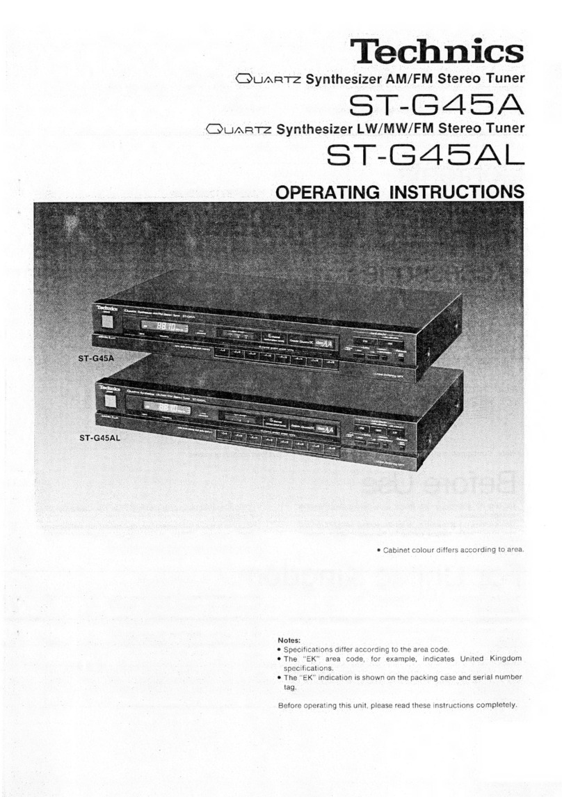
Technics ST-HD515 User manual

Technics

Technics ST-HD515 User manual

Technics ST-G560L User manual

Technics

Technics ST-G560L User manual

Technics ST-GT630 User manual

Technics

Technics ST-GT630 User manual

Technics ST-HD350 User manual

Technics

Technics ST-HD350 User manual

Technics ST-HD50 User manual

Technics

Technics ST-HD50 User manual
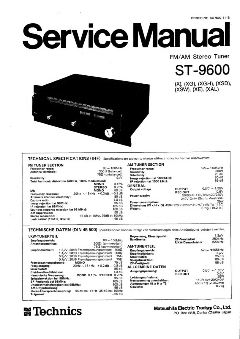
Popular Tuner manuals by other brands

Pioneer TX-9100 KUW Service manual

Pioneer

Pioneer TX-9100 KUW Service manual

Rockford Fosgate RFX8320J Installation reference sheet

Rockford Fosgate

Rockford Fosgate RFX8320J Installation reference sheet

Sony WRR-802A Service manual

Sony

Sony WRR-802A Service manual

Pioneer F-9 Service manual

Pioneer

Pioneer F-9 Service manual

Sony WRU-801A operating instructions

Sony

Sony WRU-801A operating instructions

One Remote DabWiFi6 user guide

One Remote

One Remote DabWiFi6 user guide

MediaTech MT4172 user manual

MediaTech

MediaTech MT4172 user manual

Mat-Tuner mAT-K100 instruction manual

Mat-Tuner

Mat-Tuner mAT-K100 instruction manual

Feig Electronic OBID ID AT-A Mounting instruction

Feig Electronic

Feig Electronic OBID ID AT-A Mounting instruction

Stagg CTU-C6 user manual

Stagg

Stagg CTU-C6 user manual

Onkyo T-4150 Service manual

Onkyo

Onkyo T-4150 Service manual

Eico HFT-90 instruction manual

Eico

Eico HFT-90 instruction manual

Denon TU-660 Service manual

Denon

Denon TU-660 Service manual

Onkyo T-405TX Service manual

Onkyo

Onkyo T-405TX Service manual

Advance acoustic MAT-605 manual

Advance acoustic

Advance acoustic MAT-605 manual

Jensen DLP2500 owner's manual

Jensen

Jensen DLP2500 owner's manual

Sirius XM RAdio SXV300 Accessory guide

Sirius XM RAdio

Sirius XM RAdio SXV300 Accessory guide

Yamaha TX-1000U owner's manual

Yamaha

Yamaha TX-1000U owner's manual

manuals.online logo
manuals.online logoBrands
  • About & Mission
  • Contact us
  • Privacy Policy
  • Terms and Conditions

Copyright 2025 Manuals.Online. All Rights Reserved.