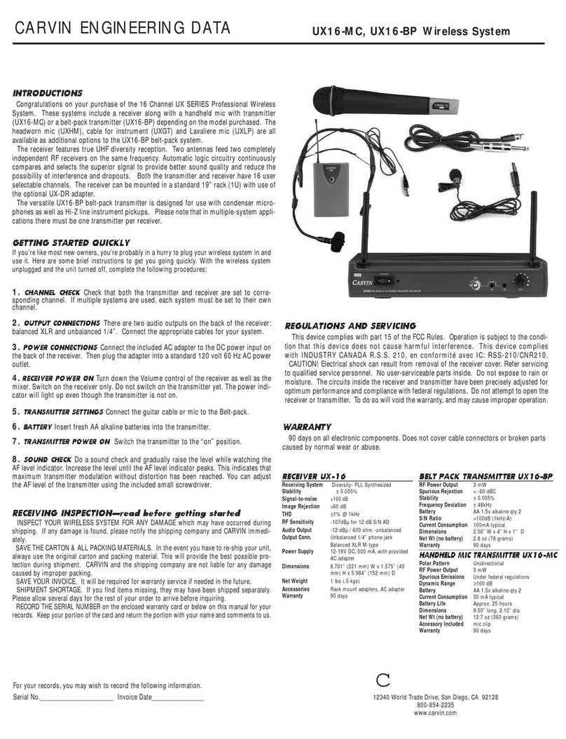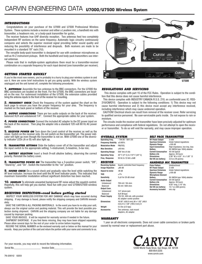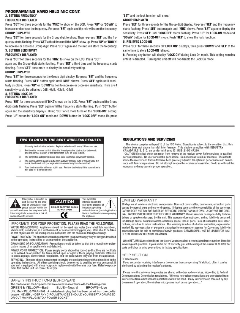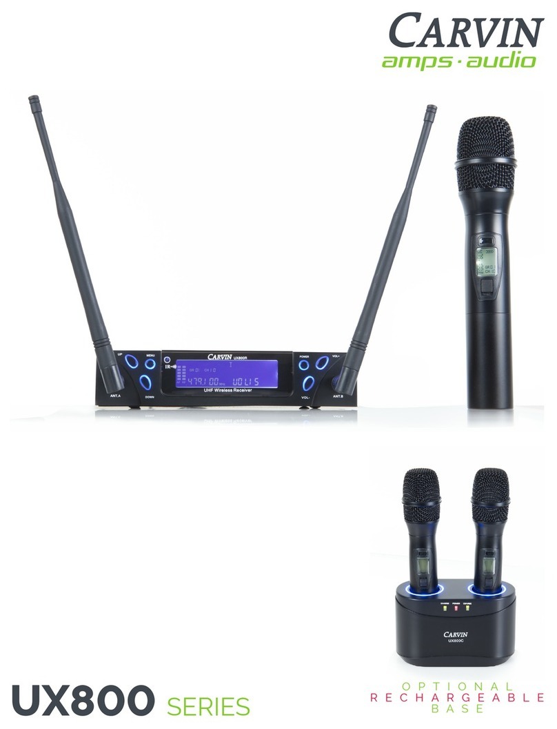
CARVIN ENGINEERING DATA SET UP
PG. 4
WIRELESS MICROPHONE SYSTEM
»1. Battery Installation
»To access the battery compartment, slide the rear
cover panel off toward the bottom. Insert fresh AA
alkaline batteries, observing correct polarity as
marked inside the battery compartment. Slide the
cover back on until it locks.
»2. POWER / MUTE Button: To turn the belt
pack ON, press and release the white button on
the top of the unit. The power button LED and
front display backlight will turn on. The channel/
frequency digits and battery status symbol will be
displayed. To MUTE the output, quickly press
and release the button. “RF OFF” will appear
on the display for 1 second. The backlight will
blink while muted, and the “no speaker” symbol
will show on the display. To UN MUTE, quickly
press and release the button again. “RF ON”
will be displayed for 1 second. To turn the unit OFF, press and hold
the button for about two seconds, the screen will display “OFF” for 1
second, then the UX600B will turn off.
»3. SETTINGS Buttons: Press and hold the SET button until
“SETUP” is displayed. The first digit will be blinking to show the
setting can be changed. Select the setting to be changed with short
presses of the SET button. Adjust the setting with the UP/DOWN
buttons. Press the SET button again to save and exit. GROUP and
CHANNEL: (example: 1- 8; group 1, channel 8) Set both numbers
to match the UX1200R receiver. FREQUENCY: (example: 530.950)
and the “MHz” symbol appears in the lower right. Allows manual
selection of the frequency, however the GROUP-CHANNEL setting
is recommended. (see UX1200R - FREQUENCY) The first 3 digits
change in 1 MHz steps, the second 3 digits change in 0.025 MHz
steps. SENSITIVITY: “SEnSiT” will display for 1 second, then the
setting value (example: 0 dB). Settings from +12dB to -18dB, in 3 dB
steps. Sets the level of the internal preamp to the transmitter. You
may want to increase this setting for soft speaking when used with
microphones, or set it lower to prevent overloading from powerful
vocals, or when connected to an instrument. The recommended
setting for electric guitar is “-9dB”, with the attenuator (ATT) set to
ON (see next paragraph). ATTENUATOR: (ATT OFF, ATT ON) Adds
an attenuation circuit when used. Recommended when connecting
instruments with the UX-GT cable, or with strong vocals through
the PERFORMER Series or UX-LP1 mics. If the SENSITIVITY setting
has been turned all the way down and the transmitter is still being
overdriven, setting ATT ON will add a buffer to the internal preamp
to allow more headroom. RF POWER: (rFP Hi, rFP Lo). Changes
the transmitter’s RF power output. Use the “rFP Hi” setting if you
experience dropouts which cannot be remedied by changing the
channel/frequency, or if the transmitter will be used far from the
receiver. Set this to “rFP Lo” if the sytem is causing interference
with another system, if used very close to the receiver, or if you are
hearing unexplainable distortion at high audio levels. SCREEN LOCK:
(Loc OFF, Loc ON): Set to “Loc ON” to prevent accidental changes
or tampering. If set to Loc ON, only the Lock screen will display
when settings are accessed. Change the setting to Loc OFF to allow
adjustments.
»4. INPUT CONNECTION: Connect one of the following to the
mini XLR input jack on the UX600B transmitter: Performer Series-
Connect the mic cable to the mini XLR input jack. Place the mic
on the vocalist’s head. Keep the mic a minimum of 2 inches from
the mouth to minimize air hitting the mic. UX-LP1 Lavaliere Mic-
Connect the lavaliere mic cable to the mini XLR input jack. Clip
the mic to clothing near the top center of the chest. For optimum
sound, position the mic as close to the mouth with the top of the mic
facing up. Test out various positions along the center of the chest to
determine the ideal mic placement. This may vary from person to
person as each voice projects uniquely. UX-GT Instrument Cable-
Connect the cable to the mini XLR input jack. Plug the 1/4” connector
into a guitar, bass or other instrument. Turn the volume down on
the receiving mixer or amplifier before
turning the transmitter power ON.
carvinaudio.com UX Series 2018-6-27
UX600B BELT-PACk TRANSmITTER
1. BATTERy INSTALLATIoN
To access the battery compartment, slide the rear cover panel off
toward the bottom. Insert fresh AA alkaline batteries, observing
correct polarity as marked inside the battery compartment. Slide
the cover back on until it locks.
2. PoWER / MUTE BUTToN
To turn the beltpack ON, press and release the white button on
the top of the unit.
The power button LED and front display backlight will turn on.
The channel/frequency digits and battery status symbol will be
displayed.
To MUTE the output, quickly press and release the button.
“RF OFF” will appear on the display for 1 second.
The backlight will blink while muted, and the “no speaker”
symbol will show on the display.
To UNMUTE, quickly press and release the button again.
“RF ON” will be displayed for 1 second.
To turn the unit OFF, press and hold the button for about two seconds, the screen will
display “OFF” for 1 second, then the UX600B will turn off.
3. SETTINGS BUTToNS
Press and hold the SET button until “SETUP” is displayed.
The first digit will be blinking to show the setting can be changed.
Select the setting to be changed with short presses of the SET button.
Adjust the setting with the UP/DOWN buttons.
Press the SET button again to save and exit.
GROUP and CHANNEL: (example: 1- 8; group 1, channel 8)
Set to both numbers match the UX1200R receiver.
FREQUENCY: (example: 530.950) and the “
MHZ”
symbol appears in the lower right.
Allows manual selection of the frequency, however the GROUP-CHANNEL setting is rec-
ommended. (see UX1200R - FREQUENCY)
The first 3 digits change in 1 MHz steps, the second 3 digits change in 0.025 MHz steps.
SENSITIVITY: “SEnSiT” will display for 1 second, then the setting value.
(example: 0 dB) Settings from +12dB to -18dB, in 3 dB steps.
Sets the level of the internal preamp to the transmitter. You may want to increase this set-
ting for soft speaking when used with microphones, or set it lower to prevent overloading
from powerful vocals, or when connected to an instrument. The recommended setting for
electric guitar is “-9dB”, with the attenuator (ATT) set to ON (see next paragraph).
ATTENUATOR: (Att OFF, Att ON) Adds an attenuation circuit when used.
Recommended when connecting instruments with the UXGT cable, or with strong vocals
through the UX-HM3 or UX-LP1 mics. If the SENSITIVITY setting has been turned all the
way down and the transmitter is still being overdriven, setting ATT ON will add a buffer to
the internal preamp to allow more headroom.
RF POWER: (rFP Hi, rFP Lo) Changes the transmitter’s RF power output.
Use the “rFP Hi” setting if you experience dropouts which cannot be remedied by chang-
ing the channel/frequency, or if the transmitter will be used far from the receiver.
Set this to “rFP Lo” if the sytem is causing interference with another system, if used very
close to the receiver, or if you are hearing unexplainable distortion at high audio levels.
SCREEN LOCK: (Loc OFF, Loc ON):
Set to “Loc ON” to prevent accidental changes or tampering. If set to Loc ON, only the
Lock screen will display when settings are accessed. Change the setting to Loc OFF to
allow adjustments.
4. INPUT CoNNECTIoN:
Connect one of the following to the mini XLR
input jack on the UX600B transmitter:
UX-HM3 HEAdSET MIC:
Connect the mic cable to the mini XLR input jack. Place
the mic on the vocalist’s head. Keep the mic a minimum of 2 inches from the mouth to
minimize air hitting the mic.
UX-LP1 LAVALIERE MIC:
Connect the lavaliere mic cable to the mini XLR input jack.
Clip the mic to clothing near the top center of the chest. For optimum sound, position the
mic as close to the mouth with the top of the mic facing up. Test out various positions
along the center of the chest to determine the ideal mic placement. This may vary from
person to person as each voice projects uniquely.
UXGT INSTRUMENT CABLE:
Connect the cable to the mini XLR input jack. Plug
the 1/4” connector into a guitar, bass or other instrument. Turn the volume down on the
receiving mixer or amplifier before turning the transmitter power ON.
Push the
round
button to
release
the cable
1. BATTERy INSTALLATIoN
(1.A, 1.B, 1.C)
While holding the lower part of the transmitter body, unscrew the windscreen capsule
(1.A) on top of the mic. Press the release clip (1.B) to eject the battery dock (1.C) and
remove it from the body. Install fresh AA alkaline batteries, observing correct polarity as
marked inside the battery compartment. Replace the battery dock and make sure the clip
snaps into the locked position so the battery dock will not slide out. Match the rectangular
stub on the windscreen capsule to the 4 pins in the mic body and turn clockwise until tight.
2. PoWER / MUTE BUTToN
To turn the mic ON, press and release the button on the bottom end of the mic.
The display and backlight will turn on.
The channel/frequency digits and battery status symbol will be displayed.
To MUTE the mic, quickly press and release the button.
“RF OFF” will appear on the display for 1 second. The
backlight will flash while muted.
To UNMUTE, quickly press and release the button again.
“RF ON” will be displayed for 1 second.
To turn the mic OFF, press and hold the button for about
two seconds, the screen wil display “OFF”, then turn off.
3. SETTINGS BUTToNS
To access the settings buttons, slide the black plastic cover off the end of the mic.
CHANGING SETTINGS:
Press and hold the SET button until “SETUP” is displayed. The setting to be edited will
be blinking. Press the SET button again to select a different setting to edit.
Adjust the setting with the UP/DOWN buttons.
Press the SET button again to save and exit.
GROUP and CHANNEL: (example: 1- 8; group 1, channel 8)
Set to both numbers match the UX1200R receiver.
FREQUENCY: (example: 530.950) and the “
MHZ”
symbol appears in the lower right.
Allows manual selection of frequency, however the GROUP-CHANNEL setting is recom-
mended. (see UX1200R - FREQUENCY)
The first 3 digits change in 1 MHz steps, the second 3 digits change in 0.025 MHz steps.
LEVEL: (example: 0 dB) range of +12dB to -18dB, in 3 dB steps.
Sets the level of the internal mic pre to the transmitter. You may want to increase this set-
ting for soft speaking, or set it lower to prevent overloading the mic from powerful vocals.
RF POWER: (rF Hi, rF Lo) Changes the transmitter’s RF power output.
Use the “rF Hi” setting if you experience dropouts which cannot be remedied by changing
the channel/frequency, or if the transmitter will be used far from the receiver.
Set this to “rF Lo” if the sytem is causing interference with another system, if used very
close to the receiver, or if you are hearing unexplainable distortion at high audio levels.
SCREEN LOCK: (Loc OFF, Loc ON): Set to “Loc ON” to prevent accidental changes or
tampering. If set to Loc ON, only the Lock screen setting will be accessable.
1
UX600m HANDHELD mICROPHONE
UX-HM3
(black)
or
UX-HM3T
(tan)
UX-LP1
UXGT
4
2
UX600B BELT-PACk TRANSmITTER
1. BATTERy INSTALLATIoN
To access the battery compartment, slide the rear cover panel off
toward the bottom. Insert fresh AA alkaline batteries, observing
correct polarity as marked inside the battery compartment. Slide
the cover back on until it locks.
2. PoWER / MUTE BUTToN
To turn the beltpack ON, press and release the white button on
the top of the unit.
The power button LED and front display backlight will turn on.
The channel/frequency digits and battery status symbol will be
displayed.
To MUTE the output, quickly press and release the button.
“RF OFF” will appear on the display for 1 second.
The backlight will blink while muted, and the “no speaker”
symbol will show on the display.
To UNMUTE, quickly press and release the button again.
“RF ON” will be displayed for 1 second.
To turn the unit OFF, press and hold the button for about two seconds, the screen will
display “OFF” for 1 second, then the UX600B will turn off.
3. SETTINGS BUTToNS
Press and hold the SET button until “SETUP” is displayed.
The first digit will be blinking to show the setting can be changed.
Select the setting to be changed with short presses of the SET button.
Adjust the setting with the UP/DOWN buttons.
Press the SET button again to save and exit.
GROUP and CHANNEL: (example: 1- 8; group 1, channel 8)
Set to both numbers match the UX1200R receiver.
FREQUENCY: (example: 530.950) and the “
MHZ”
symbol appears in the lower right.
Allows manual selection of the frequency, however the GROUP-CHANNEL setting is rec-
ommended. (see UX1200R - FREQUENCY)
The first 3 digits change in 1 MHz steps, the second 3 digits change in 0.025 MHz steps.
SENSITIVITY: “SEnSiT” will display for 1 second, then the setting value.
(example: 0 dB) Settings from +12dB to -18dB, in 3 dB steps.
Sets the level of the internal preamp to the transmitter. You may want to increase this set-
ting for soft speaking when used with microphones, or set it lower to prevent overloading
from powerful vocals, or when connected to an instrument. The recommended setting for
electric guitar is “-9dB”, with the attenuator (ATT) set to ON (see next paragraph).
ATTENUATOR: (Att OFF, Att ON) Adds an attenuation circuit when used.
Recommended when connecting instruments with the UXGT cable, or with strong vocals
through the UX-HM3 or UX-LP1 mics. If the SENSITIVITY setting has been turned all the
way down and the transmitter is still being overdriven, setting ATT ON will add a buffer to
the internal preamp to allow more headroom.
RF POWER: (rFP Hi, rFP Lo) Changes the transmitter’s RF power output.
Use the “rFP Hi” setting if you experience dropouts which cannot be remedied by chang-
ing the channel/frequency, or if the transmitter will be used far from the receiver.
Set this to “rFP Lo” if the sytem is causing interference with another system, if used very
close to the receiver, or if you are hearing unexplainable distortion at high audio levels.
SCREEN LOCK: (Loc OFF, Loc ON):
Set to “Loc ON” to prevent accidental changes or tampering. If set to Loc ON, only the
Lock screen will display when settings are accessed. Change the setting to Loc OFF to
allow adjustments.
4. INPUT CoNNECTIoN:
Connect one of the following to the mini XLR
input jack on the UX600B transmitter:
UX-HM3 HEAdSET MIC:
Connect the mic cable to the mini XLR input jack. Place
the mic on the vocalist’s head. Keep the mic a minimum of 2 inches from the mouth to
minimize air hitting the mic.
UX-LP1 LAVALIERE MIC:
Connect the lavaliere mic cable to the mini XLR input jack.
Clip the mic to clothing near the top center of the chest. For optimum sound, position the
mic as close to the mouth with the top of the mic facing up. Test out various positions
along the center of the chest to determine the ideal mic placement. This may vary from
person to person as each voice projects uniquely.
UXGT INSTRUMENT CABLE:
Connect the cable to the mini XLR input jack. Plug
the 1/4” connector into a guitar, bass or other instrument. Turn the volume down on the
receiving mixer or amplifier before turning the transmitter power ON.
Push the
round
button to
release
the cable
1. BATTERy INSTALLATIoN
(1.A, 1.B, 1.C)
While holding the lower part of the transmitter body, unscrew the windscreen capsule
(1.A) on top of the mic. Press the release clip (1.B) to eject the battery dock (1.C) and
remove it from the body. Install fresh AA alkaline batteries, observing correct polarity as
marked inside the battery compartment. Replace the battery dock and make sure the clip
snaps into the locked position so the battery dock will not slide out. Match the rectangular
stub on the windscreen capsule to the 4 pins in the mic body and turn clockwise until tight.
2. PoWER / MUTE BUTToN
To turn the mic ON, press and release the button on the bottom end of the mic.
The display and backlight will turn on.
The channel/frequency digits and battery status symbol will be displayed.
To MUTE the mic, quickly press and release the button.
“RF OFF” will appear on the display for 1 second. The
backlight will flash while muted.
To UNMUTE, quickly press and release the button again.
“RF ON” will be displayed for 1 second.
To turn the mic OFF, press and hold the button for about
two seconds, the screen wil display “OFF”, then turn off.
3. SETTINGS BUTToNS
To access the settings buttons, slide the black plastic cover off the end of the mic.
CHANGING SETTINGS:
Press and hold the SET button until “SETUP” is displayed. The setting to be edited will
be blinking. Press the SET button again to select a different setting to edit.
Adjust the setting with the UP/DOWN buttons.
Press the SET button again to save and exit.
GROUP and CHANNEL: (example: 1- 8; group 1, channel 8)
Set to both numbers match the UX1200R receiver.
FREQUENCY: (example: 530.950) and the “
MHZ”
symbol appears in the lower right.
Allows manual selection of frequency, however the GROUP-CHANNEL setting is recom-
mended. (see UX1200R - FREQUENCY)
The first 3 digits change in 1 MHz steps, the second 3 digits change in 0.025 MHz steps.
LEVEL: (example: 0 dB) range of +12dB to -18dB, in 3 dB steps.
Sets the level of the internal mic pre to the transmitter. You may want to increase this set-
ting for soft speaking, or set it lower to prevent overloading the mic from powerful vocals.
RF POWER: (rF Hi, rF Lo) Changes the transmitter’s RF power output.
Use the “rF Hi” setting if you experience dropouts which cannot be remedied by changing
the channel/frequency, or if the transmitter will be used far from the receiver.
Set this to “rF Lo” if the sytem is causing interference with another system, if used very
close to the receiver, or if you are hearing unexplainable distortion at high audio levels.
SCREEN LOCK: (Loc OFF, Loc ON): Set to “Loc ON” to prevent accidental changes or
tampering. If set to Loc ON, only the Lock screen setting will be accessable.
1.A
3
1.C 3
1.B
UX600m HANDHELD mICROPHONE
UX-HM3
(black)
or
UX-HM3T
(tan)
UX-LP1
UXGT
4
2
UX600B BELT-PACk TRANSmITTER
1. BATTERy INSTALLATIoN
To access the battery compartment, slide the rear cover panel off
toward the bottom. Insert fresh AA alkaline batteries, observing
correct polarity as marked inside the battery compartment. Slide
the cover back on until it locks.
2. PoWER / MUTE BUTToN
To turn the beltpack ON, press and release the white button on
the top of the unit.
The power button LED and front display backlight will turn on.
The channel/frequency digits and battery status symbol will be
displayed.
To MUTE the output, quickly press and release the button.
“RF OFF” will appear on the display for 1 second.
The backlight will blink while muted, and the “no speaker”
symbol will show on the display.
To UNMUTE, quickly press and release the button again.
“RF ON” will be displayed for 1 second.
To turn the unit OFF, press and hold the button for about two seconds, the screen will
display “OFF” for 1 second, then the UX600B will turn off.
3. SETTINGS BUTToNS
Press and hold the SET button until “SETUP” is displayed.
The first digit will be blinking to show the setting can be changed.
Select the setting to be changed with short presses of the SET button.
Adjust the setting with the UP/DOWN buttons.
Press the SET button again to save and exit.
GROUP and CHANNEL: (example: 1- 8; group 1, channel 8)
Set to both numbers match the UX1200R receiver.
FREQUENCY: (example: 530.950) and the “
MHZ”
symbol appears in the lower right.
Allows manual selection of the frequency, however the GROUP-CHANNEL setting is rec-
ommended. (see UX1200R - FREQUENCY)
The first 3 digits change in 1 MHz steps, the second 3 digits change in 0.025 MHz steps.
SENSITIVITY: “SEnSiT” will display for 1 second, then the setting value.
(example: 0 dB) Settings from +12dB to -18dB, in 3 dB steps.
Sets the level of the internal preamp to the transmitter. You may want to increase this set-
ting for soft speaking when used with microphones, or set it lower to prevent overloading
from powerful vocals, or when connected to an instrument. The recommended setting for
electric guitar is “-9dB”, with the attenuator (ATT) set to ON (see next paragraph).
ATTENUATOR: (Att OFF, Att ON) Adds an attenuation circuit when used.
Recommended when connecting instruments with the UXGT cable, or with strong vocals
through the UX-HM3 or UX-LP1 mics. If the SENSITIVITY setting has been turned all the
way down and the transmitter is still being overdriven, setting ATT ON will add a buffer to
the internal preamp to allow more headroom.
RF POWER: (rFP Hi, rFP Lo) Changes the transmitter’s RF power output.
Use the “rFP Hi” setting if you experience dropouts which cannot be remedied by chang-
ing the channel/frequency, or if the transmitter will be used far from the receiver.
Set this to “rFP Lo” if the sytem is causing interference with another system, if used very
close to the receiver, or if you are hearing unexplainable distortion at high audio levels.
SCREEN LOCK: (Loc OFF, Loc ON):
Set to “Loc ON” to prevent accidental changes or tampering. If set to Loc ON, only the
Lock screen will display when settings are accessed. Change the setting to Loc OFF to
allow adjustments.
4. INPUT CoNNECTIoN:
Connect one of the following to the mini XLR
input jack on the UX600B transmitter:
UX-HM3 HEAdSET MIC:
Connect the mic cable to the mini XLR input jack. Place
the mic on the vocalist’s head. Keep the mic a minimum of 2 inches from the mouth to
minimize air hitting the mic.
UX-LP1 LAVALIERE MIC:
Connect the lavaliere mic cable to the mini XLR input jack.
Clip the mic to clothing near the top center of the chest. For optimum sound, position the
mic as close to the mouth with the top of the mic facing up. Test out various positions
along the center of the chest to determine the ideal mic placement. This may vary from
person to person as each voice projects uniquely.
UXGT INSTRUMENT CABLE:
Connect the cable to the mini XLR input jack. Plug
the 1/4” connector into a guitar, bass or other instrument. Turn the volume down on the
receiving mixer or amplifier before turning the transmitter power ON.
Push the
round
button to
release
the cable
1. BATTERy INSTALLATIoN
(1.A, 1.B, 1.C)
While holding the lower part of the transmitter body, unscrew the windscreen capsule
(1.A) on top of the mic. Press the release clip (1.B) to eject the battery dock (1.C) and
remove it from the body. Install fresh AA alkaline batteries, observing correct polarity as
marked inside the battery compartment. Replace the battery dock and make sure the clip
snaps into the locked position so the battery dock will not slide out. Match the rectangular
stub on the windscreen capsule to the 4 pins in the mic body and turn clockwise until tight.
2. PoWER / MUTE BUTToN
To turn the mic ON, press and release the button on the bottom end of the mic.
The display and backlight will turn on.
The channel/frequency digits and battery status symbol will be displayed.
To MUTE the mic, quickly press and release the button.
“RF OFF” will appear on the display for 1 second. The
backlight will flash while muted.
To UNMUTE, quickly press and release the button again.
“RF ON” will be displayed for 1 second.
To turn the mic OFF, press and hold the button for about
two seconds, the screen wil display “OFF”, then turn off.
3. SETTINGS BUTToNS
To access the settings buttons, slide the black plastic cover off the end of the mic.
CHANGING SETTINGS:
Press and hold the SET button until “SETUP” is displayed. The setting to be edited will
be blinking. Press the SET button again to select a different setting to edit.
Adjust the setting with the UP/DOWN buttons.
Press the SET button again to save and exit.
GROUP and CHANNEL: (example: 1- 8; group 1, channel 8)
Set to both numbers match the UX1200R receiver.
FREQUENCY: (example: 530.950) and the “
MHZ”
symbol appears in the lower right.
Allows manual selection of frequency, however the GROUP-CHANNEL setting is recom-
mended. (see UX1200R - FREQUENCY)
The first 3 digits change in 1 MHz steps, the second 3 digits change in 0.025 MHz steps.
LEVEL: (example: 0 dB) range of +12dB to -18dB, in 3 dB steps.
Sets the level of the internal mic pre to the transmitter. You may want to increase this set-
ting for soft speaking, or set it lower to prevent overloading the mic from powerful vocals.
RF POWER: (rF Hi, rF Lo) Changes the transmitter’s RF power output.
Use the “rF Hi” setting if you experience dropouts which cannot be remedied by changing
the channel/frequency, or if the transmitter will be used far from the receiver.
Set this to “rF Lo” if the sytem is causing interference with another system, if used very
close to the receiver, or if you are hearing unexplainable distortion at high audio levels.
SCREEN LOCK: (Loc OFF, Loc ON): Set to “Loc ON” to prevent accidental changes or
tampering. If set to Loc ON, only the Lock screen setting will be accessable.
1
1.A
3
1.C 3
1.B
UX600m HANDHELD mICROPHONE
UX-HM3
(black)
or
UX-HM3T
(tan)
UX-LP1
UXGT
4
2
»1. Battery Installation (1.A, 1.B, 1.C)
»While holding the lower part of the transmitter body, unscrew the
windscreen capsule (1.A) on top of the mic. Press the release clip
(1.B) to eject the battery dock (1.C) and remove it from the body.
Install fresh AA alkaline batteries, observing correct polarity as
marked inside the battery compartment. Replace the battery dock
and make sure the clip snaps into the locked position so the battery
dock will not slide out. Match the rectangular stub on the windscreen
capsule to the 4 pins in the mic body and turn clockwise until tight.
»2. POWER / MUTE Button
»To turn the mic ON, press and release the button
on the bottom end of the mic. The display and
backlight will turn on. The channel/frequency digits
and battery status symbol will be displayed. To
MUTE the mic, quickly press and release the button. “RF OFF” will
appear on the display for 1 second. The backlight will flash while
muted. To UN MUTE, quickly press and release the button again. “RF
ON” will be displayed for 1 second. To turn the mic OFF, press and
hold the button for about two seconds, the screen will display “OFF”
then turn off.
»3. SETTINGS Buttons
»To access the settings buttons, slide the black plastic cover off
the end of the mic. CHANGING SETTINGS: Press and hold the SET
button until “SETUP” is displayed. The setting to be edited will be
blinking. Press the SET button again to select a different setting to
edit. Adjust the setting with the UP/DOWN buttons. Press the SET
button again to save and exit. GROUP and CHANNEL: (example:
1- 8; group 1, channel 8) Set both numbers to match the UX1200R
receiver. FREQUENCY: (example: 530.950) and the “MHz” symbol
appears in the lower right. Allows manual selection of frequency,
however the GROUP-CHANNEL setting is recommended. (see
UX1200R - FREQUENCY) The first 3 digits change in 1 MHz steps, the
second 3 digits change in 0.025 MHz steps. LEVEL: (example: 0 dB)
range of +12dB to -18dB, in 3 dB steps. Sets the level of the internal
mic pre to the transmitter. You may want to increase this setting for
soft speaking, or set it lower to prevent overloading the mic from
powerful vocals. RF POWER: (rF Hi, rF Lo) Changes the transmitter’s
RF power output. Use the “rF Hi” setting if you experience dropouts
which cannot be remedied by changing the channel/frequency, or if
the transmitter will be used far from the receiver. Set this to “rF Lo” if
the system is causing interference with another system, if used very
close to the receiver, or if you are hearing unexplainable distortion at
high audio levels. SCREEN LOCK: (Loc OFF, Loc ON): Set to “Loc ON”
to prevent accidental changes or tampering. If set to Loc ON, only
the Lock screen setting will be accessible.
UX600B BELT-PACk TRANSmITTER
1. BATTERy INSTALLATIoN
To access the battery compartment, slide the rear cover panel off
toward the bottom. Insert fresh AA alkaline batteries, observing
correct polarity as marked inside the battery compartment. Slide
the cover back on until it locks.
2. PoWER / MUTE BUTToN
To turn the beltpack ON, press and release the white button on
the top of the unit.
The power button LED and front display backlight will turn on.
The channel/frequency digits and battery status symbol will be
displayed.
To MUTE the output, quickly press and release the button.
“RF OFF” will appear on the display for 1 second.
The backlight will blink while muted, and the “no speaker”
symbol will show on the display.
To UNMUTE, quickly press and release the button again.
“RF ON” will be displayed for 1 second.
To turn the unit OFF, press and hold the button for about two seconds, the screen will
display “OFF” for 1 second, then the UX600B will turn off.
3. SETTINGS BUTToNS
Press and hold the SET button until “SETUP” is displayed.
The first digit will be blinking to show the setting can be changed.
Select the setting to be changed with short presses of the SET button.
Adjust the setting with the UP/DOWN buttons.
Press the SET button again to save and exit.
GROUP and CHANNEL: (example: 1- 8; group 1, channel 8)
Set to both numbers match the UX1200R receiver.
FREQUENCY: (example: 530.950) and the “
MHZ”
symbol appears in the lower right.
Allows manual selection of the frequency, however the GROUP-CHANNEL setting is rec-
ommended. (see UX1200R - FREQUENCY)
The first 3 digits change in 1 MHz steps, the second 3 digits change in 0.025 MHz steps.
SENSITIVITY: “SEnSiT” will display for 1 second, then the setting value.
(example: 0 dB) Settings from +12dB to -18dB, in 3 dB steps.
Sets the level of the internal preamp to the transmitter. You may want to increase this set-
ting for soft speaking when used with microphones, or set it lower to prevent overloading
from powerful vocals, or when connected to an instrument. The recommended setting for
electric guitar is “-9dB”, with the attenuator (ATT) set to ON (see next paragraph).
ATTENUATOR: (Att OFF, Att ON) Adds an attenuation circuit when used.
Recommended when connecting instruments with the UXGT cable, or with strong vocals
through the UX-HM3 or UX-LP1 mics. If the SENSITIVITY setting has been turned all the
way down and the transmitter is still being overdriven, setting ATT ON will add a buffer to
the internal preamp to allow more headroom.
RF POWER: (rFP Hi, rFP Lo) Changes the transmitter’s RF power output.
Use the “rFP Hi” setting if you experience dropouts which cannot be remedied by chang-
ing the channel/frequency, or if the transmitter will be used far from the receiver.
Set this to “rFP Lo” if the sytem is causing interference with another system, if used very
close to the receiver, or if you are hearing unexplainable distortion at high audio levels.
SCREEN LOCK: (Loc OFF, Loc ON):
Set to “Loc ON” to prevent accidental changes or tampering. If set to Loc ON, only the
Lock screen will display when settings are accessed. Change the setting to Loc OFF to
allow adjustments.
4. INPUT CoNNECTIoN:
Connect one of the following to the mini XLR
input jack on the UX600B transmitter:
UX-HM3 HEAdSET MIC:
Connect the mic cable to the mini XLR input jack. Place
the mic on the vocalist’s head. Keep the mic a minimum of 2 inches from the mouth to
minimize air hitting the mic.
UX-LP1 LAVALIERE MIC:
Connect the lavaliere mic cable to the mini XLR input jack.
Clip the mic to clothing near the top center of the chest. For optimum sound, position the
mic as close to the mouth with the top of the mic facing up. Test out various positions
along the center of the chest to determine the ideal mic placement. This may vary from
person to person as each voice projects uniquely.
UXGT INSTRUMENT CABLE:
Connect the cable to the mini XLR input jack. Plug
the 1/4” connector into a guitar, bass or other instrument. Turn the volume down on the
receiving mixer or amplifier before turning the transmitter power ON.
Push the
round
button to
release
the cable
1. BATTERy INSTALLATIoN
(1.A, 1.B, 1.C)
While holding the lower part of the transmitter body, unscrew the windscreen capsule
(1.A) on top of the mic. Press the release clip (1.B) to eject the battery dock (1.C) and
remove it from the body. Install fresh AA alkaline batteries, observing correct polarity as
marked inside the battery compartment. Replace the battery dock and make sure the clip
snaps into the locked position so the battery dock will not slide out. Match the rectangular
stub on the windscreen capsule to the 4 pins in the mic body and turn clockwise until tight.
2. PoWER / MUTE BUTToN
To turn the mic ON, press and release the button on the bottom end of the mic.
The display and backlight will turn on.
The channel/frequency digits and battery status symbol will be displayed.
To MUTE the mic, quickly press and release the button.
“RF OFF” will appear on the display for 1 second. The
backlight will flash while muted.
To UNMUTE, quickly press and release the button again.
“RF ON” will be displayed for 1 second.
To turn the mic OFF, press and hold the button for about
two seconds, the screen wil display “OFF”, then turn off.
3. SETTINGS BUTToNS
To access the settings buttons, slide the black plastic cover off the end of the mic.
CHANGING SETTINGS:
Press and hold the SET button until “SETUP” is displayed. The setting to be edited will
be blinking. Press the SET button again to select a different setting to edit.
Adjust the setting with the UP/DOWN buttons.
Press the SET button again to save and exit.
GROUP and CHANNEL: (example: 1- 8; group 1, channel 8)
Set to both numbers match the UX1200R receiver.
FREQUENCY: (example: 530.950) and the “
MHZ”
symbol appears in the lower right.
Allows manual selection of frequency, however the GROUP-CHANNEL setting is recom-
mended. (see UX1200R - FREQUENCY)
The first 3 digits change in 1 MHz steps, the second 3 digits change in 0.025 MHz steps.
LEVEL: (example: 0 dB) range of +12dB to -18dB, in 3 dB steps.
Sets the level of the internal mic pre to the transmitter. You may want to increase this set-
ting for soft speaking, or set it lower to prevent overloading the mic from powerful vocals.
RF POWER: (rF Hi, rF Lo) Changes the transmitter’s RF power output.
Use the “rF Hi” setting if you experience dropouts which cannot be remedied by changing
the channel/frequency, or if the transmitter will be used far from the receiver.
Set this to “rF Lo” if the sytem is causing interference with another system, if used very
close to the receiver, or if you are hearing unexplainable distortion at high audio levels.
SCREEN LOCK: (Loc OFF, Loc ON): Set to “Loc ON” to prevent accidental changes or
tampering. If set to Loc ON, only the Lock screen setting will be accessable.
1
1.A
3
1.C 3
1.B
UX600m HANDHELD mICROPHONE
UX-HM3
(black)
or
UX-HM3T
(tan)
UX-LP1
UXGT
4
2
