CARVIN PWS2001 User manual

CAUTION
RISK OF ELECTRIC SHOCK
DO NOT OPEN
SAFETY INSTRUCTIONS (EUROPEAN)
The conductors in the AC power cord are colored in accordance with the following code.
GREEN & YELLOW—Earth BLUE—Neutral BROWN—Live
U.K. MAIN PLUG WARNING: A molded main plug that has been cut off from the cord is
unsafe. NEVER UNDER ANY CIRCUMSTANCES SHOULD YOU INSERT A DAM-
AGED OR CUT MAIN PLUG INTO A POWER SOCKET.
IMPORTANT! FOR YOUR PROTECTION, PLEASE READ THE FOLLOWING:
WATER AND MOISTURE: Appliance should not be used near water (near a bathtub, washbowl,
kitchen sink, laundry tub, in a wet basement, or near a swimming pool, etc). Care should be taken
so that objects do not fall and liquids are not spilled into the enclosure through openings.
POWER SOURCES: The appliance should be connected to a power supply only of the type
described in the operating instructions or as marked on the appliance.
GROUNDING OR POLARIZATION: Precautions should be taken so that the grounding or polar-
ization means of an appliance is not defeated.
POWER CORD PROTECTION: Power supply cords should be routed so that they are not like-
ly to be walked on or pinched by items placed upon or against them, paying particular atten-
tion to cords at plugs, convenience receptacles, and the point where they exit from the appli-
ance.
SERVICING: The user should not attempt to service the appliance beyond that described in
the operating instructions. All other servicing should be referred to qualified service person-
nel.
This symbol is intended to
alert the user to the pres-
ence of uninsulated “dan-
gerous voltage” within the
product’s enclosure that may be of suf-
ficient magnitude to constitute a risk of
electric shock to persons.
This symbol is intend-
ed to alert the user to
the presence of impor-
tant operating and
maintenance (servicing) instructions
in the literature accompanying the
appliance.
LIMITED WARRANTY
Your Carvin product is guaranteed against failure for ONE YEAR unless otherwise stated. Vacuum
tubes are guaranteed for 90 days. Carvin will service and supply all parts at no charge to the cus-
tomer providing the unit is under warranty. Shipping costs are the responsibility of the customer.
CARVIN DOES NOT PAY FOR PARTS OR SERVICING OTHER THAN OUR OWN. A COPY OF THE
ORIGINAL INVOICE IS REQUIRED TO VERIFY YOUR WARRANTY. Carvin assumes no responsibility
for horn drivers or speakers damaged by this unit. This warranty does not cover, and no liability is
assumed, for damage due to: natural disasters, accidents, abuse, loss of parts, lack of reasonable
care, incorrect use, or failure to follow instructions. This warranty is in lieu of all other warranties,
expressed or implied. No representative or person is authorized to represent or assume for Carvin
any liability in connection with the sale or servicing of Carvin products. CARVIN SHALL NOT BE
LIABLE FOR INCIDENTAL OR CONSEQUENTIAL DAMAGES.
When RETURNING merchandise to the factory, you may call for a return authorization number.
Describe in writing each problem. If your unit is out of warranty, you will be charged the current FLAT
RATE for parts and labor to bring your unit up to factory specifications.
HELP SECTION
RF Interference
If you encounter receiving interference (from other than an operating TV station), often it can be
eliminated by adjusting the receiver’s squelch control, as described in this manual.
Please note that wireless frequencies are shared with other audio services. According to Federal
Communications Commission regulations, “Wireless microphone operations are unprotected from
interference from other licensed operations within the band. If any interference is received by any
Government or non-Government operation, the wireless microphone must cease operation…”
If you need assistance with operation or frequency selection, please contact Carvin’s service
department.
Application Freq. Code Freq. (MHz)
• Traveling frequencies T2 169.505
(Normally work anywhere in the U.S.A. and Canada, T3 170.245
but as a result tend to be crowded T8 171.905
• For use only where there is no channel 7: 8G 175.800
7I 176.200
• For use only where there is no channel 8: 8D 181.200
8M 183.200
8S 184.200
• For use only where there is no channel 9: 9F 187.600
9Q 189.800
• For use only where there is no channel 10: 10C 193.000
10J 194.400
10W 196.800
• For use only where there is no channel 11: 11G 199.800
11S 202.200
• For use only where there is no channel 12: 12L 207.000
12S 208.200
12V 208.600
• For use only where there is no channel 13: 13B 210.800
13Q 213.800
Multi-channel Systems
Following are groupings of frequencies suggested for multi-channel wireless systems.
• For use where TV channels 7, 9, 11 and/or 13 are operating: 8D-8M-8S-10C-10J-10W-12L-12S-12V
Traveling frequencies T2, T3 and/or T8 may be used with any of the above frequencies except for: 8D, 8M and 10C.
Interference may result from the use of these frequency combinations.
• For use where TV channels 8, 10 and/or 12 are operating: 7G-7I-9F-9Q-11G-11S-13Q or
7G-7I-9F-11G-11S-13B-13Q
Traveling frequencies T2, T3 and/or T8 may be used with any of the above frequencies with no interference problems.
CARVIN WIRELESS OPERATING FREQUENCIES
For future reference, please record your system information here (the serial numbers appear
inside the battery compartment of each transmitter, and on the bottom of each receiver):
Operating Frequency
Freq. Code____ ____ ____ Frequency____ ____ ____ •____ ____ ____ MHz
Receiver
Model_________________ Serial Number____ ____ ____ ____ ____ ____ ____
Transmitter
Model_________________ Serial Number____ ____ ____ ____ ____ ____ ____
ACCESSORIES
PWS-RMA Rack-mount antenna kit brings antenna inputs
to the front of receiver for ease of setup.
PWS-VPC Vinyl pouch with belt clip holds UniPak.
PWS-WSC Foam windscreen for handheld transmitter.
PWS-WRP Water-resistant pouch for UniPak transmitter.
PWS-STC Stand clamp for handheld, 5/8”-27 threads.
PWS-XLR Connecting cable for UniPak transmitter with
an XLRF-type input connector, for Lo-Z mics
with XLRM-type output terminations.
PWS-PAK UniPack™ transmitter
PWS-MIC Handheld microphone
PWS-GTR 1/4” instrument cable
PWS-HWM Headset mic
PWS-LPM Lapel condenser mic

OVERALL SYSTEM
Operating Freq. VHF high band, 169 MHz to 216 MHz
Frequency Stability ±0.005%, single-frequency
crystal-controlled
Modulation Mode FM
Max Deviation ±30 kHz, traveling freq. ±15 kHz
Operating Range 200’ minimum
Operating Temp 40° F (4° C) to 110° F (43° C)
Freq. Response 100 Hz to 15 kHz
RECEIVER
Receiving System Dual independent receivers, auto-
matic switching diversity reception
Image Rejection ≥60 dB
Signal-to-noise
.80 dB at 10 kHz deviation (IEC-weighted)
THD ≤1% (10 kHz deviation @ 1 kHz)
Sensitivity 10 µV for 60 dB S/N (IEC-weighted)
Audio Output
Unbalanced 350 mV (at 1 kHz, ±10 kHz deviation,
10k ohm load)
Balanced 220 mV (at 1 kHz, ±10 kHz deviation,
10k ohm load)
Output Conn.
Unbalanced 1/4” phone jack
Balanced XLRM-type
Power Supply 12-18V DC, 350 mA, with provided
AC adapter
Dimensions 16.93” (430.0 mm) W x 1.92” (48.8
mm) H x 7.28” (185.0 mm) D
Weight 5.5 lbs (2.5 kgs)
Accessories Two whip antennas, rack mount
adapters, AD1205A AC adapter
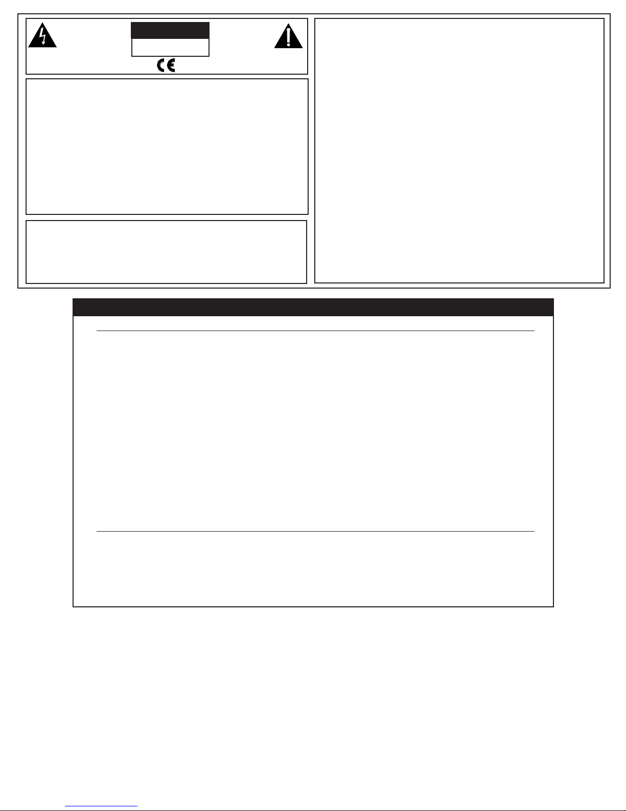
INTRODUCTION
Thank you for choosing a Carvin professional wireless system. You have joined thou-
sands of other satisfied customers who have chosen our products because of their quali-
ty, performance and reliability. This Carvin wireless microphone system is the successful
result of years of design and manufacturing experience.
This professional wireless system includes a receiver and either a body-pack or a hand-
held transmitter on a specific crystal-controlled frequency.
The receiver features true diversity reception. Two antennas feed two completely inde-
pendent RF sections on the same frequency; automatic logic circuitry continuously com-
pares and selects the superior received signal, providing better sound quality and reduc-
ing the possibility of interference and dropouts. The receiver is made to be mounted in a
standard 19” rack (1U).
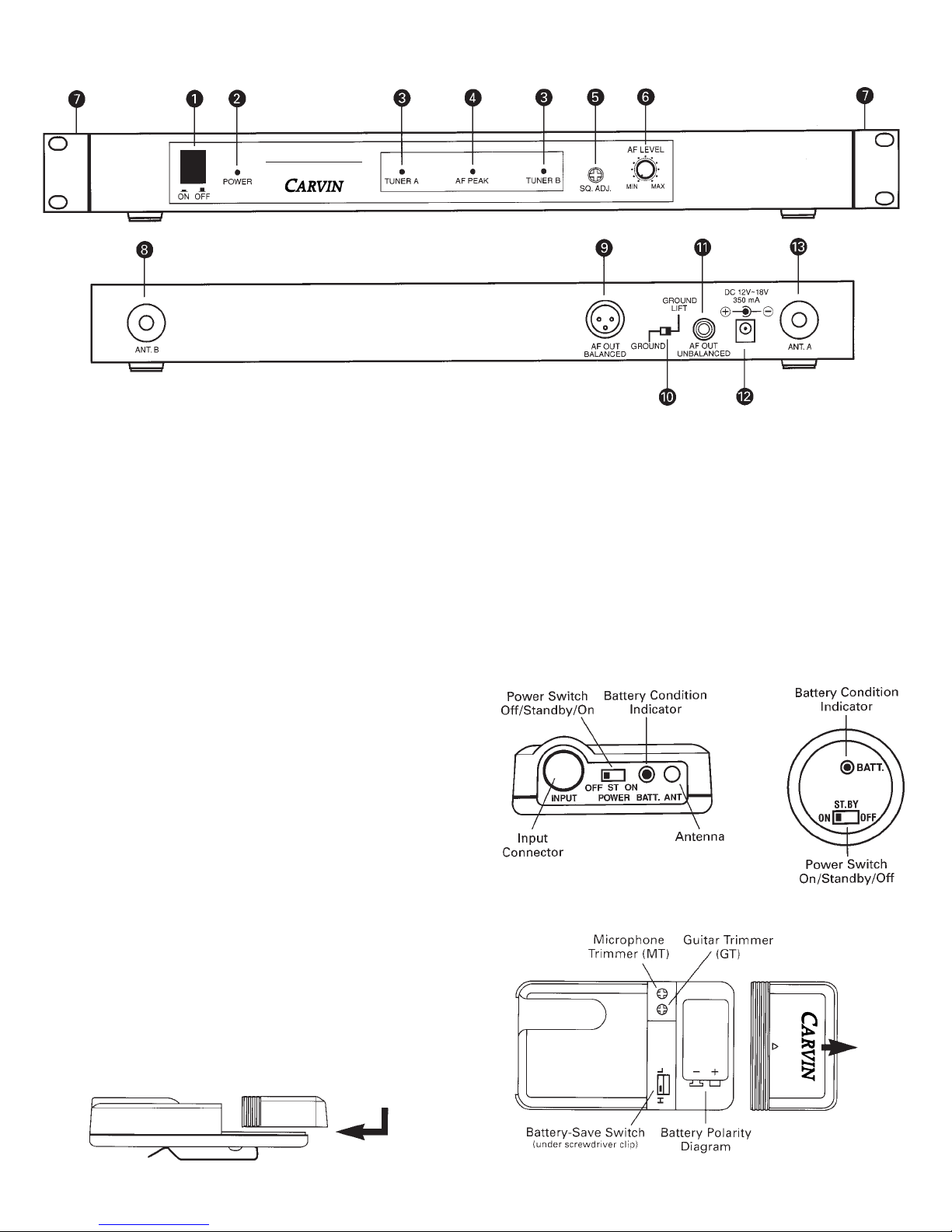
The versatile UniPack™ body-pack transmitter has both low- and high-impedance inputs
plus a bias connection, for use with dynamic and electret condenser microphones, as well
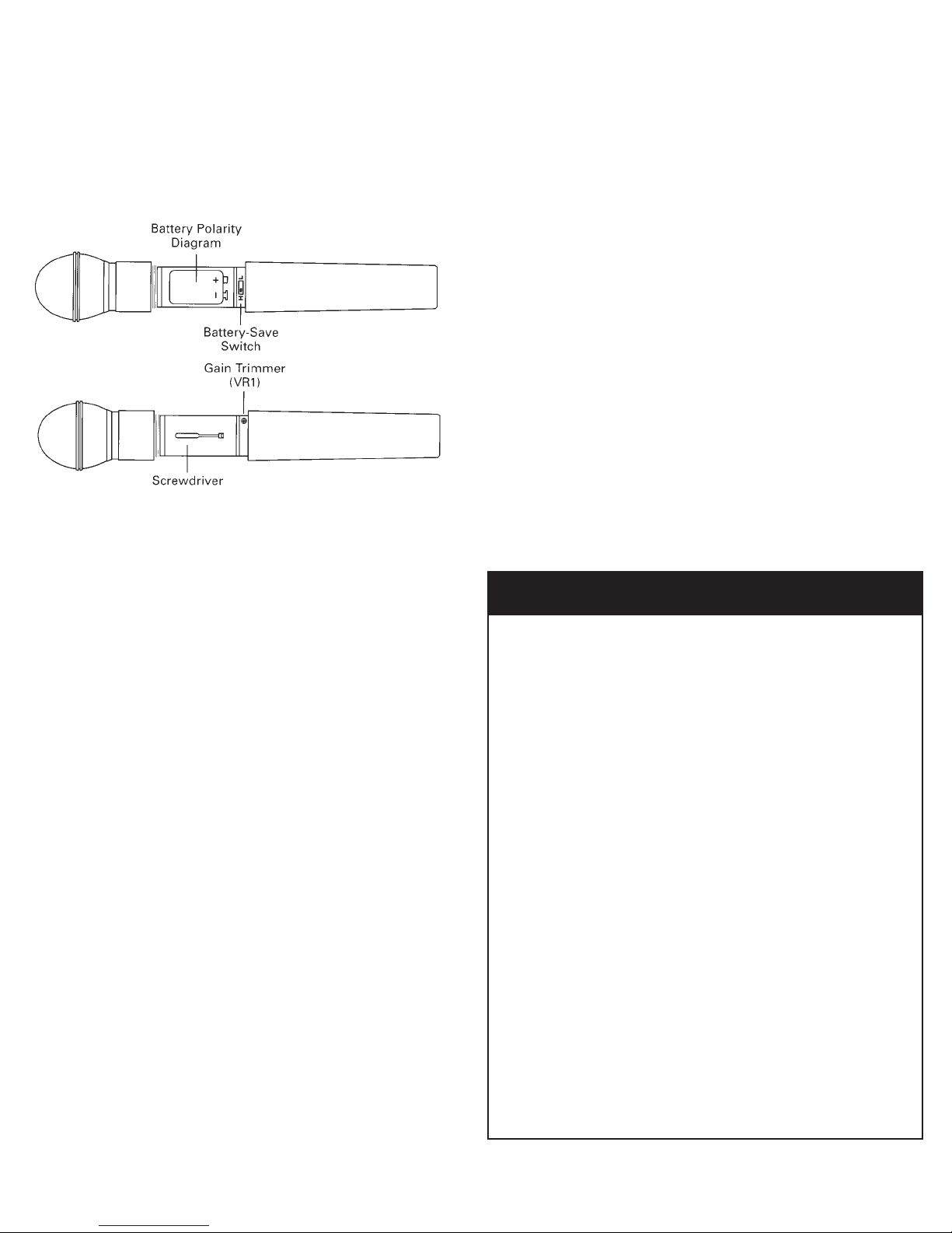
as Hi-Z instrument pickups. Both the handheld and UniPack transmitters use internal 9-
volt batteries and have Off/Standby/On switches, battery condition indicators, and battery-
save switches.
Please note that in multiple-system applications there must be a transmitter-receiver
combination on a separate frequency for each input desired (only one transmitter for each
receiver). Because the wireless frequencies are in or near VHF TV frequencies, only cer-
tain wireless frequencies are useable in a particular geographical area. Also, only certain
of the available operating frequencies may be used together. (Frequency selection infor-
mation will be found on the back cover.)
INSTALLATION AND OPERATION
This device complies with part 15 of the FCC Rules. Operation is subject to the condi-
tion that this device does not cause harmful interference.
This device complies with INDUSTRY CANADA R.S.S. 210, en conformite´ avec IC: RSS-
210/CNR210. Operation is subject to the following conditions: 1) This device may not
cause harmful interference and 2) this device must accept any interference received,
including interference which may cause undesired operation.
CAUTION! Electrical shock can result from removal of the receiver cover. Refer servicing
to qualified service personnel. No user-serviceable parts inside. Do not expose to rain or
moisture.
The circuits inside the receiver and transmitter have been precisely adjusted for optimum
performance and compliance with federal regulations. Do not attempt to open the receiv-
er or transmitter. To do so will void the warranty, and may cause improper operation.
RECEIVER INSTALLATION
LOCATION
For best operation the receiver should be at least
3 ft. above the ground and at least 3 ft. away from
a wall or metal surface to minimize reflections.
The transmitter should also be at least 3 ft. away
from the receiver, as shown in figure A.
Keep antennas away from noise sources such as
motors, automobiles, and neon lights, as well as
large metal objects.
For your records, you may wish to record the following information.
Serial No._____________________ Invoice Date_______________
PWS-PAK UNIPAK™ TRANSMITTER
RF Power Output 50 mW max
Spurious Emissions Under federal regulations
Dynamic Range ≥90 dB
Input Connections High impedance, low imp, bias
Battery 9V (NEDA type 1604) alkaline
Current Consumption 30 mA typical
Battery Life Approx. 15 hours in “H” position
Approx. 20 hours in “L” position
Dimensions 2.56” W x 4.33” H x 1.00” D
Net Wt (no battery) 2.8 oz (78 grams)
Accessories Included Hi-Z input cable
PWS-MIC HANDHELD TRANSMITTER
Polar Pattern Unidirectional
RF Power Output 50 mW max
Spurious Emissions Under federal regulations
Dynamic Range ≥90 dB
Microphone Element
PWS-DYM Audio-Technica dynamic
Battery 9V (NEDA type 1604) alkaline
Current Consumption 30 mA typical
Battery Life Approx. 15 hours in “H” position
Approx. 20 hours in “L” position
Dimensions 9.50” long, 2.10” dia.
Net Wt (no battery) 12.7 oz (360 grams)
Accessory Included Stand clamp
76-20012 898
12340 World Trade Drive, San Diego, CA 92128
(619) 487-1600 (800) 854-2235
www.carvin.com
RECEIVING INSPECTION—read before getting started
INSPECT YOUR WIRELESS SYSTEM FOR ANY DAMAGE which may have occurred during
shipping. If any damage is found, please notify the shipping company and CARVIN immedi-
ately.
SAVE THE CARTON & ALL PACKING MATERIALS. In the event you have to re-ship your unit,
always use the original carton and packing material. This will provide the best possible pro-
tection during shipment. CARVIN and the shipping company are not liable for any damage
caused by improper packing.
SAVE YOUR INVOICE. It will be required for warranty service if needed in the future.
SHIPMENT SHORTAGE. If you find items missing, they may have been shipped separately.
Please allow several days for the rest of your order to arrive before inquiring.
RECORD THE SERIAL NUMBER on the enclosed warranty card or below on this manual for your
records. Keep your portion of the card and return the portion with your name and comments to us.
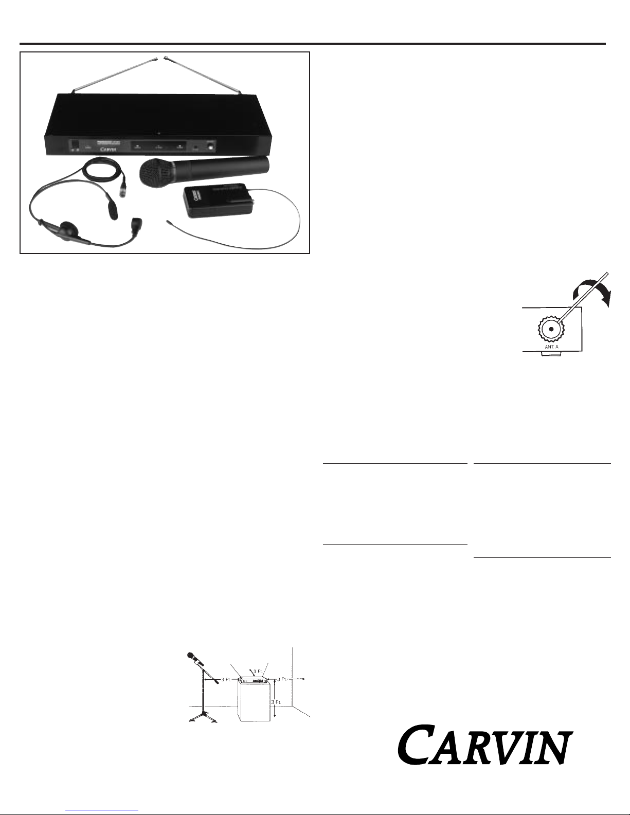
OUTPUT CONNECTIONS
There are two audio outputs on the back of the receiver: balances (220 mV) and unbal-
anced (350 mV). Use shielded audio cable for the connection between the receiver and
the mixer. If the input of the mixer is a 1/4” jack, connect a cable from the 1/4” unbal-
anced audio output on the back of the receiver to the mixer. If the input of the mixer is
an XLR-type input, connect a cable from the balanced XLR-type audio output on the back
of the receiver to the mixer.
The two isolated audio outputs permit simultaneous feeds to both unbalanced and bal-
anced inputs. For example, both a guitar amp and a mixer can be driven by the receiv-
er.
ANTENNAS
Assemble the two whip antennas to the special connec-
tors provided. Screw the whips into the threaded side
holes at the rear of the connector (Fig. B).
Attach the antennas to the antenna input jacks. The
antennas are normally positioned in the shape of a “V”
(45° from vertical) for best reception.
Do not try to move the antenna rod after the connector
shell has been tightened down. Always loosen the connector shell completely before
repositioning the rod.
If there is not sufficient space above the receiver and/or if the receiver is installed in a
metal cabinet, the antennas can be mounted in the threaded holes in the back of the con-
nectors so the antennas will stick straight out from the back of the receiver. Use one set
of threaded holes or the other; do not attempt to bend the antenna rods. (The optional
accessory PWS-RMA rack-mount antenna kit brings antenna inputs to the front of the
receiver.)
POWER CONNECTIONS
Connect the included AD1205A AC adapter to the DC power input on the back of the
CARVIN ENGINEERING DATA
PWS2001 UniPak™ Transmitter System
PWS2002 Handheld Dynamic Microphone System
Fig. B
Fig. A

FRONT PANEL CONTROLS AND FUNCTIONS
1. POWER SWITCH: Press switch on, and the “power” indicator will light.
2. POWER INDICATOR.
3. TUNER OPERATION INDICATORS: Indicates when maximum transmitter modula-
tion without distortion has been reached.
5. SQUELCH CONTROL: Adjusts the level of noise-muting circuit (preset at factory but
can be adjusted as circumstances warrant).
6. AF LEVEL CONTROL: Adjusts level at both audio output jacks. Does not affect AF
Peak indicator.
7. MOUNTING ADAPTERS: For mounting the receiver in any standard 19” rack. Attach
to receiver with screws supplied.
REAR PANEL CONTROLS AND FUNCTIONS
8. TUNER “B” ANTENNA JACK: Antenna connector for tuner”B.” Attach the antenna
directly, or extend it with an antenna cable.
9. BALANCED AUDIO OUTPUT JACK: XLRM-type connector. A standard 2-conductor
shielded cable can be used to connect the receiver output to a balanced aux-level
input on a mixer.
10. GROUND LIFT SWITCH: Disconnects the ground pin of the balanced output (9)
from ground. Normally, the switch should be to the left (ground connected). If
hum caused by a ground loop occurs, slide switch to the right.
11. UNBALANCED AUDIO OUTPUT JACK: 1/4” phone jack. Can be connected to an
unbalanced aux-level input of a mixer or tape recorder.
12. DC POWER INPUT: For the provided AD1205A AC adapter, or other 12-18V DC
source. (Receiver requires 350 mA.)
13. TUNER “A” ANTENNA JACK: Antenna connector for tuner “A.” Attach the antenna
directly, or extend it with an antenna cable.
TRANSMITTER SETUP
BATTERY SELECTION
An alkaline 9-volt battery is recommended.
UniPak™ Transmitter Battery Installation:
1. Slide off the battery cover as shown in Figure E.
2. Carefully insert a fresh 9-volt alkaline battery, observing correct polarity as marked
inside the battery compartment. The transmitter housing is designed to prevent incor-
rect installation of the battery. Do not force the battery in.
3. Replace the battery cover (Fig. F.).
BATTERY CONDITION INDICATOR:
The red battery condition indicator (Fig. I/J) should light strongly with a fresh battery.
As the battery weakens, the indicator will grow dimmer. When the indicator becomes
very dim or goes out, there is little life left in the battery. Replace it at once for contin-
ued operation af the transmitter.
BATTERY-SAVE SWITCH
All transmitters feature battery-save switches (Fig. E/G). As supplied, the switch is set
in the “H” (high) position for maximum range. Switching to the :L: (low) position
increases battery life by reducing power. (Note: Effective range decreases when the
switch is set at the :L: position.)
The UniPak transmitter is supplied with a Hi-Z cable. The cable is wired for use with guitars or
other high-impedance sources.
FRONT & REAR PANEL CONTROLS
Fig. E
Fig. I Fig. J
Fig. F
Fig. C
Fig. D
PWS2000
SERIES
VHF DIVERSITY RECEIVER
PWS-PAK
TRANSMITTER

HANDHELD TRANSMITTER BATTERY INSTALLATION:
1. While holding the upper part of the transmitter body just below the ball-screen,
unscrew the lower body cover and slide it downward to expose the battery compart-
ment.
2. Lift the white “battery keeper” arm, and insert a 9V battery. Be certain to observe
correct polarity as marked inside the battery compartment (Fig. G). The transmitter
housing is designed to prevent incorrect installation of the battery. Do not force the
battery in.
3. Replace the lower body cover. Do not overtighten.
SYSTEM OPERATION
Check the frequency of the system against the chart on page 7 to ensure you have the
proper frequency for your area. The frequency is marked on the back panel of the
receiver.
Turn down the AF Level control of the receiver as well as the mixer. Switch on the
receiver only. Do not switch on the transmitter yet.
RECEIVER ON…
The power indicator will light up and one of the diversity indicator LEDs (A or B) will
light, even though the transmitter is not on.
TRANSMITTER ON…
The transmitters have a 3-position power switch. When the switch is set to “Standby,”
the transmitter produces both RF and audio. With the switch “Off,” there is minimum
noise output due to a special muting system.
RECEIVER SQUELCH
The squelch control on the front panel of the receiver is preset at the factory, but can
be adjusted if you must use the system in an area with considerable RF interference. If
there is audio output from the receiver when your transmitter is off, adjust the squelch
control so the system will receive the signal from your transmitter but “squelch” or
eliminate the unwanted background RF noise. This adjustment can cause a reduction
in useable range of the wireless transmitter, so set the control to the lowest position
that reliably mutes the unwanted RF signals.
INPUT LEVEL ADJUSTMENT
Input trimmer controls in the transmitters enable you to use microphones or guitars
with different sensitivities, or to adjust for different acoustic levels.
Caution! The small trimmer controls are delicate; use only the supplied screwdriver. Do
not force the trimmers beyond their normal 260° range of rotation.
Return the screwdriver to its storage clip when not in use.
UNIPAK TRANSMITTER
Slide the battery cover off the top part of transmitter and remove the screwdriver from
its clip (Fig. E). Gently turn the “MT” (mic trimmer) and :GT” (guitar trimmer) controls
to their full counter-clockwise positions.
ADJUSTING MICROPHONE INPUT LEVEL:
With typically-loud acoustic input level to the microphone, carefully turn the MT control
clockwise while watching the receiver’s AF Peak indicator. Increase the MT control set-
ting until the AF Peak indicator lights. This indicates that maximum transmitter modu-
lation without significant distortion has been reached. (When using a guitar, return the
MT control setting to minimum.)
ADJUSTING GUITAR / INSTRUMENT INPUT LEVEL:
While playing at typically-loud levels, carefully turn the GT control clockwise while
watching the receiver’s AF Peak indicator. Increase the GT control setting until the AF
Peak indicator lights. This indicates that maximum transmitter modulation without sig-
nificant distortion has been reached. (When using a microphone, return the GT control
setting to minimum.)
After adjusting input levels, return the screwdriver to its clip and reinstall the battery
cover. No further transmitter gain adjustments should be needed, as long as the input
device and the acoustic input level are not changed.
HANDHELD TRANSMITTER
Unscrew the lower body cover and slide it downward, exposing the screwdriver and
gain trimmer (Fig. H). Remover the screwdriver and gently turn this gain trimmer con-
trol to its full counter-clockwise position.
With acoustic input to the microphone at typically-loud levels, carefully turn the trim-
mer control clockwise while watching the receiver’s AF Peak indicator. Increase the
control setting until the AF Peak indicator lights. This indicates that maximum trans-
mitter modulation without significant distortion has been reached.
Return the screwdriver to its clip and close and secure the lower body. (Make certain
that the white “battery keeper” arm is inside the body.) No further transmitter adjust-
ments should be needed, as long as the acoustic input does not change significantly.
FREQUENCY SELECTION
Each transmitter/receiver system operates on a single factory-aligned, crystal-con-
trolled frequency. Available frequencies are shown in the chart below.
Operating frequency is specified by a two- or three-character code, such as”T2” or
“11G,” in addition to the actual frequency in MHz. The frequency of each transmitter
appears on a label on the outside of the unit. The frequency of the receiver appears on
a label on the back of the unit and the frequency of each system appears on the outer
carton. For future reference, please record them in the space provided.
Because most of these authorized frequencies are shared with TV broadcasting, fre-
quency selection is largely dependent upon which TV broadcast channels are in opera-
tion where the wireless system is to be used.
Fig. G
Fig. H
1. Use only fresh alkaline batteries. Do not use (carbon-zinc) batteries.
2. Position the receiver so that it has the fewest possible obstructions between
it and the normal location of the transmitter. Line-of-sight is best.
3. The transmitter and receiver should be as close together as conveniently
possible.
4. The receiver antenna should be in the open and away from any metal. If in
a rack, have the unit on top or angle antennas outward away from the metal
rack.
5. A receiver cannot receive signals from two transmitters at the same time.
6. The power switch on the transmitter has three positions:
“Off,” “Standby” and “On.” In the middle “Standby” position, the transmit-
ter sends only RF to the receiver; the audio source is turned off.
7. For best operation, adjust the guitar or mic trimmer only until the maximum
output lights the AF Peak indicator (don’t overmodulate).
8. If the AF Level control of the receiver is set too high, it may over-drive the
input of the mixer or clip the output of the receiver, causing distortion. If
the receiver output is set too low, the overall signal-to-noise ratio of the
system may be reduced.
Adjust the output level of the receiver so the highest sound pressure level
going into the microphone causes no input overload in the mixer, and yet
permits the mixer level controls to operate in their”normal” range (not set
too high or too low). This provides optimum signal-to-noise for the entire
system.
9. Turn the transmitter off when not in use. Remove the battery if the trans-
mitter is not to be used for a period of time.
10. In multiple-system applications, set the battery-save switches on “L” (low)
is possible, to reduce the chance of intermodulation problems.
TEN TIPS TO OBTAIN THE BEST RESULTS
This manual suits for next models
1
Other CARVIN Microphone System manuals

CARVIN
CARVIN PM100 WIRELESS User manual

CARVIN
CARVIN UX600 User manual

CARVIN
CARVIN UX600B User manual

CARVIN
CARVIN UX16-MC User manual

CARVIN
CARVIN UH6000 User manual

CARVIN
CARVIN UX800 Series User manual

CARVIN
CARVIN UH5000 User manual

CARVIN
CARVIN UX1000BP User manual

CARVIN
CARVIN USM16BP User manual

CARVIN
CARVIN U7000 User manual
Popular Microphone System manuals by other brands

Behringer
Behringer ULTRALINK ULM2000 user manual

Chameleon Audio Products
Chameleon Audio Products IMC-1001 user manual

Inkel
Inkel IRM-816 Operation manuals

Studio Evolution
Studio Evolution SE-200D operating manual

BST
BST UDR116 instruction manual

Beamreach networks
Beamreach networks BeamPlex BRU-150 quick guide