WRT-800A (AU) 1-2
Notes on Use
On channel selection
•
The microphone/transmitter and tuners are classified by
frequency band.
A 14-MHz frequency band (or two consecutive-
numbered TV channels, such as 66 and 67 of the WRT-
800A) is assigned to each microphone/transmitter and
tuner model.
In building up a UHF wireless microphone system, be
sure to combine a microphone/transmitter and a tuner
having the same TV channel number.
•
Make sure that the channel selected on the microphone is
the same as that selected on the tuner used in the same
system.
•
Depending on the noise or interference conditions, the
selectable channels may not necessarily all be usable. If
necessary, you can determine the usable channels by
stepping the channel selection through a number of
channels on a tuner with the microphone set to OFF.
Those channels on which the RF indicator of the tuner
does not light are usable.
•
If there is a TV broadcasting station near by, do not use
the station’s channel.
On microphone system operation
•
To operate with 2 or more channels, maintain a distance
of at least 30 cm (1 ft.) between each pair of microphones.
For details of operation with 2 or more channels, refer to
the Operating Instructions for the WRR-800A/801A/850A
UHF Synthesized Diversity Tuners.
•
Ensure that the tuners set to channels not being used are
either turned off or set to the minimum output level.
•
When powering the microphone on or off, to keep the
noise to a minimum, set the audio output level from the
tuner or mixer to a minimum.
•
Powering the microphone on without checking the
channel selection first may interfere with the operation of
other microphones/transmitters, if the current setting is
already being used.
•
Separate the reception antennas and the microphone by
more than 3 m (10 ft.).
On battery
•
Use a new alkaline battery, and check the recommended
“useby” date on the bottom of the battery.
•
Be careful to insert the battery with the correct polarity.
•
When not using the wireless microphone for a long period,
remove the battery to avoid leakage. If a battery does leak,
clean all leakage from the unit and insert new battery.
Leakage left in the unit may cause poor battery contact. If
there seems to be poor battery contact, consult your Sony
dealer.
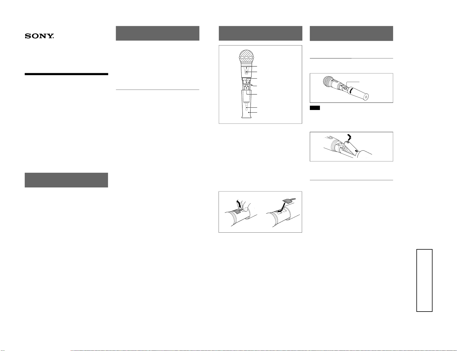
On the antenna
Do not touch the antenna while using as it will significantly
degrade good performance, causing drop outs, etc.
The WRT-800A can transmit on any selected wireless
channel among those listed below.
Channels and Carrier
Frequencies
WL Channel Frequency (MHz) WL Channel Frequency (MHz)
66-01 792.250 67-01 799.250
66-02 792.375 67-02 799.375
66-03 792.500 67-03 799.500
66-04 792.625 67-04 799.625
66-05 792.750 67-05 799.750
66-06 792.875 67-06 799.875
66-07 793.000 67-07 800.000
66-08 793.125 67-08 800.125
66-09 793.250 67-09 800.250
66-10 793.375 67-10 800.375
66-11 793.500 67-11 800.500
66-12 793.625 67-12 800.625
66-13 793.750 67-13 800.750
66-14 793.875 67-14 800.875
66-15 794.000 67-15 801.000
66-16 794.125 67-16 801.125
66-17 794.250 67-17 801.250
66-18 794.375 67-18 801.375
66-19 794.500 67-19 801.500
66-20 794.625 67-20 801.625
66-21 794.750 67-21 801.750
66-22 794.875 67-22 801.875
66-23 795.000 67-23 802.000
66-24 795.125 67-24 802.125
66-25 795.250 67-25 802.250
66-26 795.375 67-26 802.375
66-27 795.500 67-27 802.500
66-28 795.625 67-28 802.625
66-29 795.750 67-29 802.750
66-30 795.875 67-30 802.875
66-31 796.000 67-31 803.000
66-32 796.125 67-32 803.125
66-33 796.250 67-33 803.250
66-34 796.375 67-34 803.375
66-35 796.500 67-35 803.500
66-36 796.625 67-36 803.625
66-37 796.750 67-37 803.750
66-38 796.875 67-38 803.875
66-39 797.000 67-39 804.000
66-40 797.125 67-40 804.125
66-41 797.250 67-41 804.250
66-42 797.375 67-42 804.375
66-43 797.500 67-43 804.500
66-44 797.625 67-44 804.625
66-45 797.750 67-45 804.750
66-46 797.875 67-46 804.875
66-47 798.000 67-47 805.000
66-48 798.125 67-48 805.125
66-49 798.250 67-49 805.250
66-50 798.375 67-50 805.375
66-51 798.500 67-51 805.500
Specifications
Transmitter and modulator section
Oscillator Crystal controlled PLL synthesizer
Carrier frequencies 792.250 to 805.500 MHz
(102 settings at 125 kHz intervals)
Tone signal 32.768 kHz
Type of emission 110KF3E
RF power output 5 mW
Frequency stability Within ±0.002%
Type of antenna
1
/
4
-wavelength helical
Pre-emphasis 50 µs
Reference deviation ±5 kHz (94 dB SPL, 1 kHz)
(0 dB SPL = 2 ×10
–5
Pa)
Frequency response 100 to 13,000 Hz
Signal-to-noise ratio 57 dB or more
(A-weighted, with reference
deviation at WRR-800A/801A)
Maximum input 128 dB SPL (1 kHz)
Microphone unit Electret condenser microphone
Directivity Uni-directional
Power section
Power requirements 1.5 V DC
(one LR6/size AA alkaline battery)
Battery life Approx. 12 hours at 25°C (77°F)
with Sony LR6 alkaline battery
General
Operating temperature 0°C to +50°C (32°F to 122°F)
Storage temperature –30°C to +60°C (–22°F to +140°F)
Dimensions 55 ×216 mm (2
1
/
4
×8
5
/
8
inches)
(Maximum dia. ×length)
Mass Approx. 200 g (7.1 oz) including
battery
Supplied accessories
Microphone holder (1)
Stand adaptor PF
1
/
2
to W
3
/
8
(1)
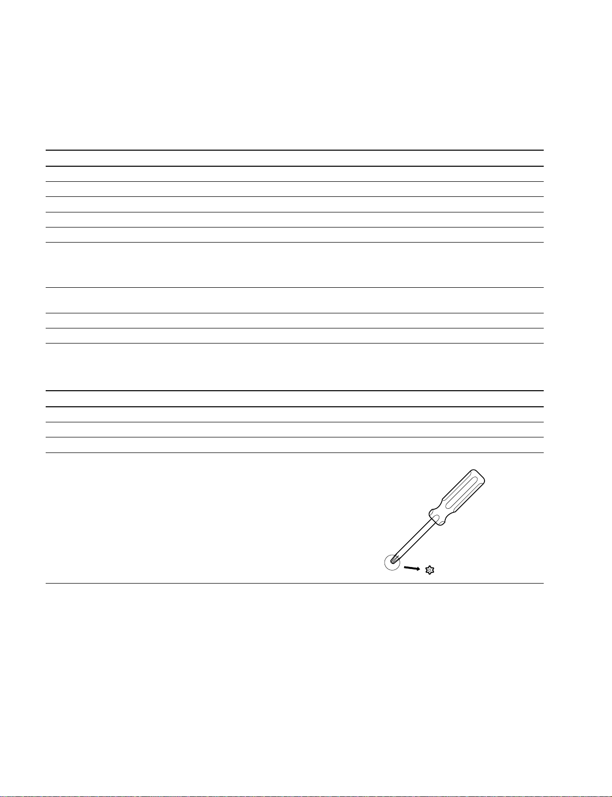
Screwdriver (1)
Operating Instructions (1)
Design and specifications are subject to change without
notice.
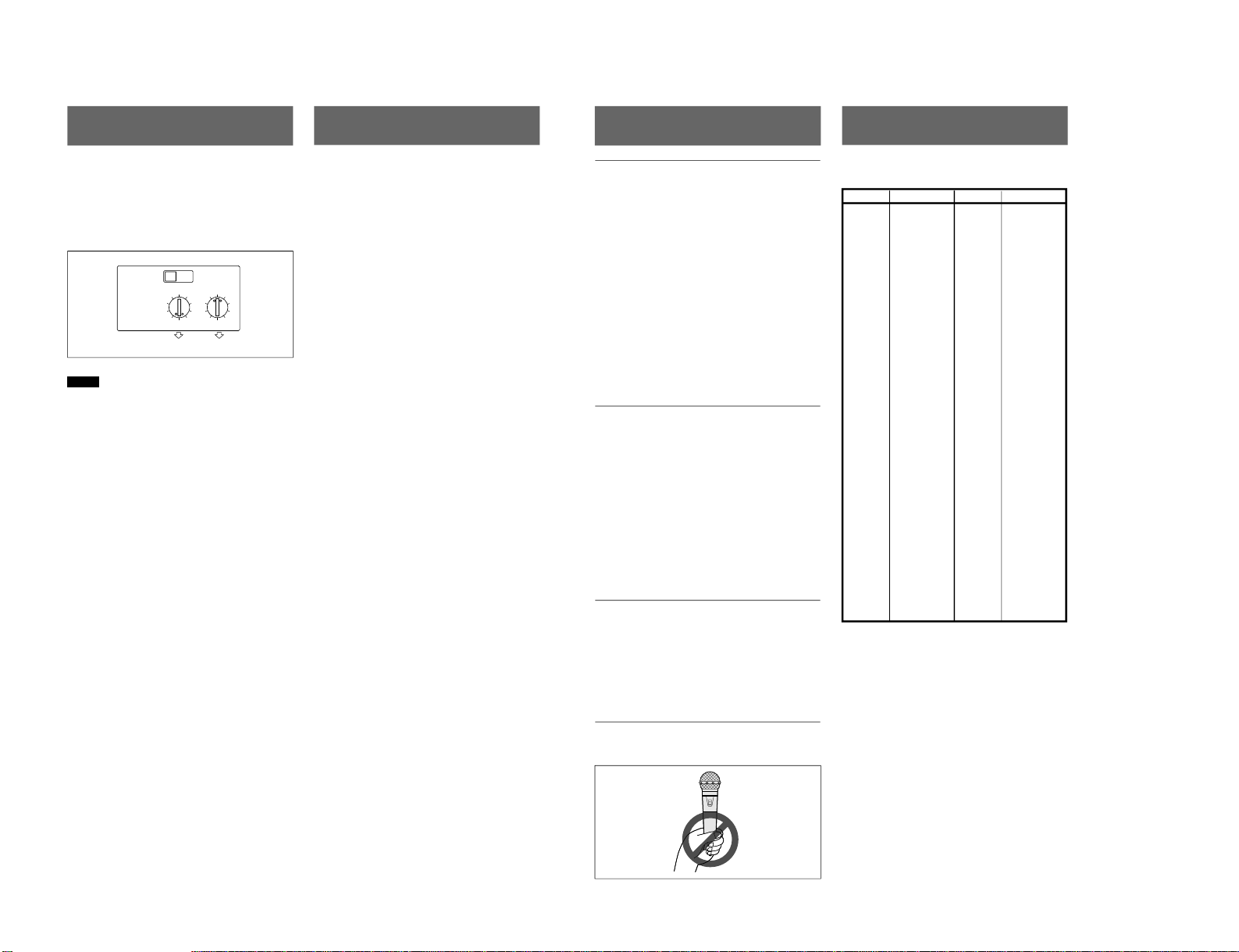
Channel Setting
Check that the power is off and set the channel select
switches for the desired channel using the supplied
screwdriver.
Set the upper slide switch to 66 or 67 and set the rotary
switches to the last two digits of the desired wireless
channel.
Example: To set to channel 66-05
Notes
•
Turn off the microphone when setting the transmitting
channel to eliminate interference or noise on other
wireless equipment.
If the channel select switches are operated while the
microphone is on, the power indicator flashes as a
warning.
•
If you set to any channel other than those listed in the
table on the page on the rear, the power indicator flashes
as a warning.
•
The microphone does not transmit while the power
indicator is flashing.
6766
5
0
347
28
6
19
5
0
3
47
28
6
19
05