© Panasonic Corporation 2010. All rights reserved.
Unauthorized copying and distribution is a violation
of law.
PSG1002003CE
Wireless System
Model No. SH-FX71GC
SH-FX71GN
Product Color: (K)...Black Type
TABLE OF CONTENTS
PAGE PAGE
1 Safety Precautions----------------------------------------------- 2
1.1. General Guidelines---------------------------------------- 2
1.2. Before Repair and Adjustment ------------------------- 3
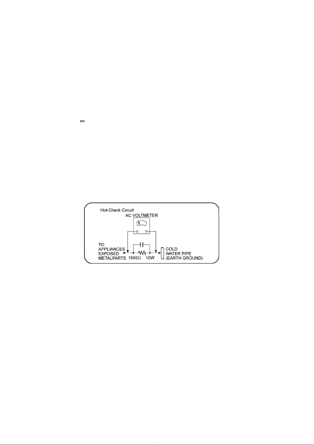
1.3. Protection Circuitry ---------------------------------------- 3
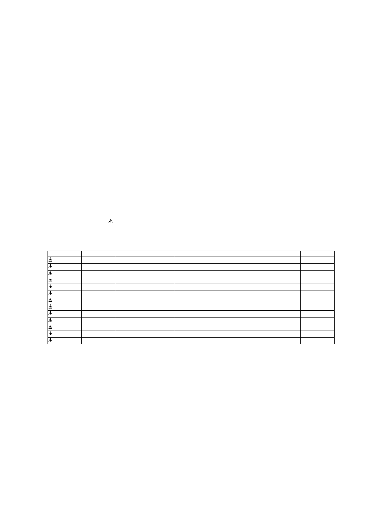
1.4. Safety Part Information----------------------------------- 3
2 Warning -------------------------------------------------------------- 4
2.1. Prevention of Electro Static Discharge (ESD)
to Electrostatically Sensitive (ES) Devices---------- 4
2.2. Service caution based on Legal restrictions -------- 5
3 Service Navigation ----------------------------------------------- 6
3.1. Service Hint ------------------------------------------------- 6
4 Specifications ----------------------------------------------------- 7
5 Operating Instructions------------------------------------------ 8
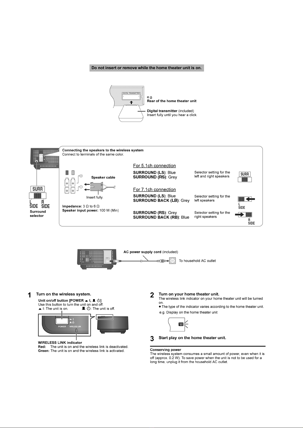
5.1. Digital Transmitter connection-------------------------- 8
5.2. Surround Speakers connection to the Digital
Receiver ----------------------------------------------------- 8
5.3. AC Power Supply Cord connection ------------------- 8
5.4. Making the Wireless link --------------------------------- 8
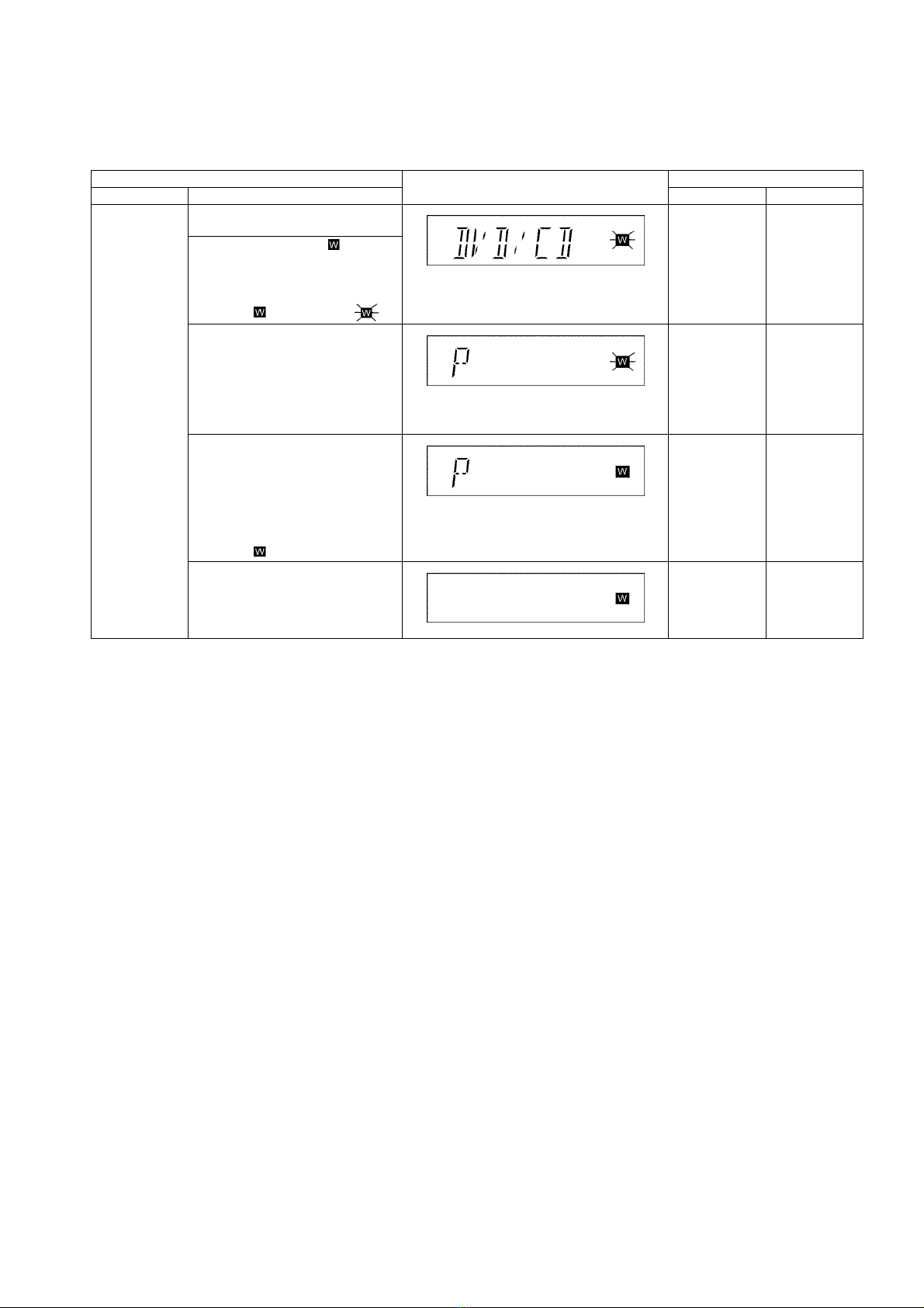
6 Service Mode ------------------------------------------------------ 9
6.1. Service Mode Table 1 ------------------------------------ 9
7 Disassembly and Assembly Instructions ---------------10
7.1. Main Parts Location Diagram--------------------------11
7.2. Disassembly flow chart----------------------------------12
7.3. Disassembly of Digital Receiver ----------------------13
8 Service Position -------------------------------------------------18
8.1. Checking & Repairing LED Drive P.C.B. and
LED P.C.B.------------------------------------------------- 18
8.2. Checking & Repairing D-AMP P.C.B. --------------- 18
9 Voltage Measurement & Waveform Chart--------------- 19
9.1. D-AMP P.C.B. --------------------------------------------- 19
9.2. LED P.C.B.------------------------------------------------- 19
9.3. Waveform Chart ------------------------------------------ 19
10 Illustration of IC’s, Transistors and Diodes ------------ 20
11 Block Diagram --------------------------------------------------- 21
11.1. RECEIVER BLOCK DIAGRAM----------------------- 21
12 Wiring Connection Diagram--------------------------------- 23
12.1. Digital Receiver------------------------------------------- 23
13 Schematic Diagram Notes ----------------------------------- 24
14 Schematic Diagram -------------------------------------------- 25
14.1. D-AMP CIRCUIT ---------------------------------------- 25
14.2. LED DRIVE CIRCUIT and LED CIRCUIT-------- 26
15 Printed Circuit Board ------------------------------------------ 27
15.1. D-AMP P.C.B., LED DRIVE P.C.B. and LED
P.C.B. ------------------------------------------------------- 27
16 Exploded View and Replacement Parts List ----------- 29
16.1. Exploded View and Mechanical Replacement
Parts List --------------------------------------------------- 29
16.2. Electrical Replacement Parts List-------------------- 34