CAS Corporation TW-100 User manual

B
BT
T
I
IN
ND
DI
IC
CA
AT
TO
OR
R
-
--
--
--
--
--
--
--
--
--
--
--
--
--
--
--
--
--
--
--
--
--
--
--
--
--
-
M
MO
OD
DE
EL
L
:
:
T
TW
W-
-1
10
00
0
--------------------------
- PAGE 1 -

T
Ta
ab
bl
le
e
o
of
f
C
Co
on
nt
te
en
nt
ts
s
1. TECHNICAL SPECIFICATION ................................ PAGE 3
2. OVERALL VIEW ...................................................... PAGE 4
3. CONNECTION ......................................................... PAGE 4
4. TEST MODE ........................................................... PAGE 5
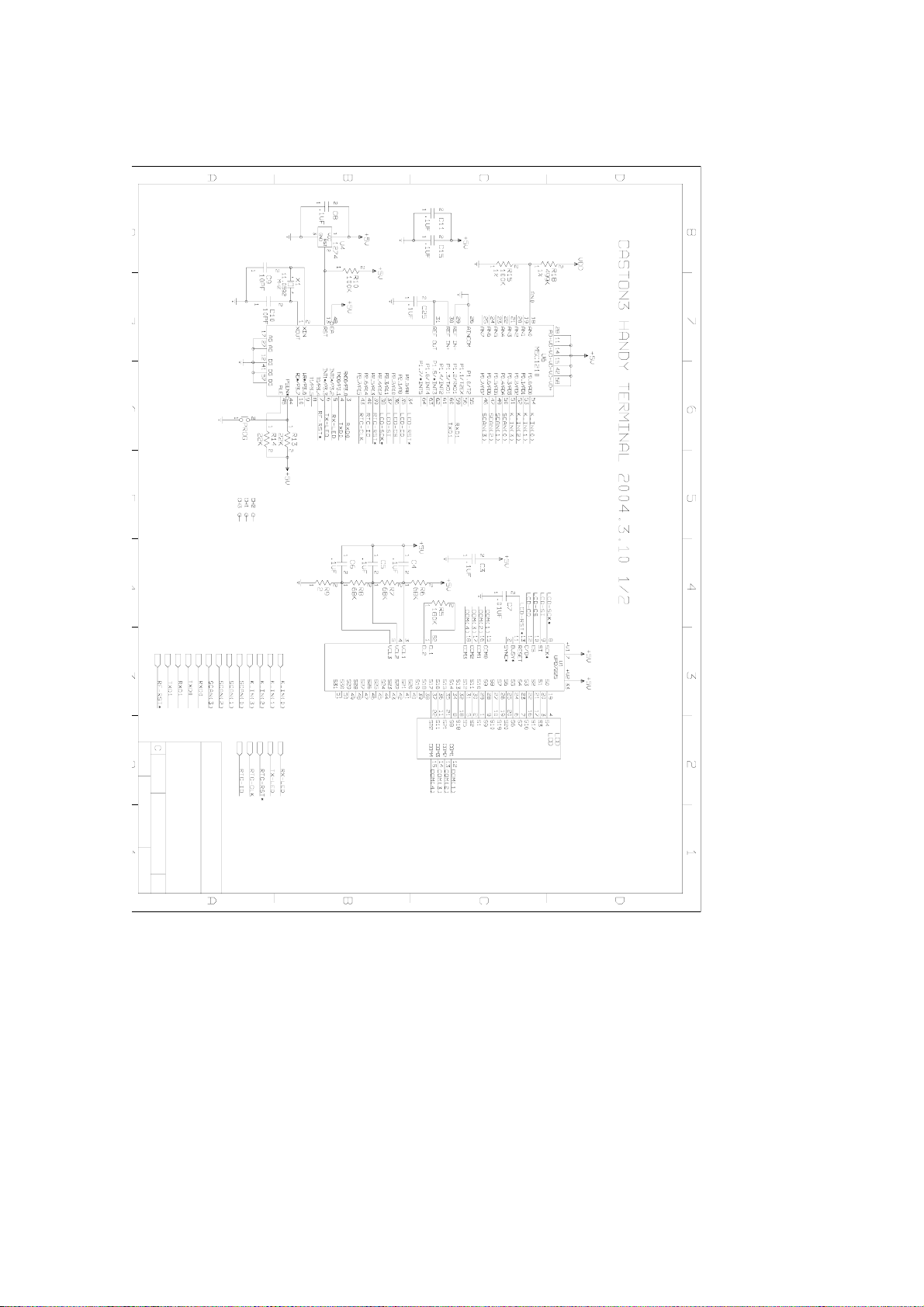
5. SCHEMATIC DIAGRAM ......................................... PAGE 6
6. P.C.B DIAGRAM ............ ........................................ PAGE 9
7. BLOCK DIAGRAM .................................................. PAGE 11
10. CONNECTOR DIAGRAM ....................................... PAGE 12
11. DEVICE OF SPECIFICATION ................................ PAGE 13
12. PART LIST .............................................................. PAGE 13
13. EXPLODED VIEW................................................... PAGE 16
14. ERROR MESSAGE & TROUBLE SHOOTING ....... PAGE 17
15. PRINT FORMAT DOWNLOAD ………………......... PAGE 17
16. PROGRAM DOWNLOAD ………………………....... PAGE 18
- PAGE 2 -

1. TECHNICAL SPECIFICATION
■Technical Specification
Display LCD (5 digit)
Size of letter 12mm (Height)
Display below zero “-” minus signal
Status Lamp ZERO, GROSS, NET, TARE, PRINT, HOLD
Power TW-100 : Rechargeable DC Battery 7.2V 750mA
Charger : AC220V/60Hz
Power consumption 0.5 W/h
Operation temperature -10℃to +40℃
Frequency 2402Mhz ~2483Mhz
Channel 79 channels
Channel interval 1 Mhz
Communication method FSK(Frequency Shift Keying fsk)
Comm. speed 9600bps
Comm. distance Approximate 50M ~ 100M
- PAGE 3 -

2. OVERALL VIEW
,'
,'
3. CONNECTION
(1) Connection of serial printer
RXD 3ᄋ------------------------------------ ᄋTransmit Data
TXD 2ᄋ------------------------------------ ᄋReceive Data
GND 7ᄋ------------------------------------ ᄋSignal Ground
TW-100 charger RS-232C port 9pin port(Female) Print port
- PAGE 4 -

4. TEST MODE
HOW TO ENTER
1) Turn on power while pressing ZERO key and TEST mode starts.
LCD CHECK MODE
1) All letters of LCD will be turned on.
2) Press ON/OFF key to move the next mode.
KEY CHECK MODE
1) The LCD window displays “0-“
2) It will display the key number pressed.
3) Press ON/OFF key to move the next mode.
COMMUNICATION (RS-232) CHECK MODE
1) The LCD window displays “t- r-“.
2) Transmit key number value when one of key 0~9 is pressed.
3) ASCII ‘0~9’ is transmitted, the display of TW-100 will show.
4) If ON/OFF key is pressed, ‘out’ message is transmitted and TEST MODE is ended.
LCD DISPLAY EXPLANATION
tESt 1 All letters of LCD turn on
tESt 2 Displays TW-100key number
tESt 3 Displays the transmitted data of TW-100 and the
received data from PC
- PAGE 5 -

(1) MAIN
5. SCHEMATIC DIAGRAM
- PAGE 6 -

- PAGE 7 -

(2) CHARGER
-
+
D3
RB153
R11
1K
C3
0.1uF
C2
0.1uF
R9
6.4K F
U1
PIC16F676
1
4
3
2
12
14
5
13
6
7
11
10
8
9
VDD
RA3/MCLR
RA4/OSC2
RA5/OSC1
AN1/RA1
VSS
RC5
AN0/RA0
RC4
RC3/AN7
AN2/RA2
AN4/RC0
AN6/RC2
AN5/RC1
CN5
전면
LED
R6
1K
F1
221/100V
Q2
2N7002
+5V
+5V
U3
LM7805
1
3
2
VIN
G
N
D
VOUT
CN2
LPH03-03
1
2
3
R10
3.6K F
Q1
FDS6679
CN6
TO BATTER Y
1
2
3
4
5
CN3
LPH03-02
1
2
D2
1N4007
C7
0.1uF
TW-100-01
1.0
CAS INDUSTRIAL TW-100 NI-MH CHARGER
A4
11Friday , D ecember 02, 2005
Smart Power Management Co.Ltd.
Title
Size Document Number Rev
Date: Sheet of
+5V
LD2
GREEN
LD3
RED
+12V
CN1
LPH03-02
1
2
R12
1K
+5V
BD1
BEAD 5mm
250V/315mA
FUSE
+
C6
470/16V
CN5
5267-03
1
2
3
CN4
5267-05
1
2
3
4
5
+12V
LD1
RED
BD2
BEAD 5mm
JP2
220V
U2
LM317T
3
1
2
VIN
A
D
J
VOUT
+12V
RY1
RY -12W-K
R3
47K
D1
B240
R7
8K F
C1
0.1uF
+12V
R2
2K F
+
C5
470/50V
R8
4K F
R5
3.3/2W
R4
1K
R1
10K F
C4
0.1uF
JP1
110V
CN7
5264-05
1
2
3
4
5
- PAGE 8 -

6. P.C.B DIAGRAM
(1) MAIN P.C.B
- PAGE 9 -

(2) Charger P.C.B
(4) CHG P.C.B
- PAGE 10 -

7. BLOCK DIAGRAM
1
1
2
2
BLUETOOTH MODULE
MCU
(MSC 1210)
DRIVER
(UPD7225)
DISPLAY
(LCD)
RS-232
(MAX232)
PRINTER
PC
POWER
MANAGEMENT
BATTERY
11.0592MHz
<FIG 1>
- PAGE 11 -

8. CONNECTOR DIAGRAM
1) MAIN PCB
6100-PTW-0010-0
MAIN PCB
PROG
(DOWNLOAD CONNECTOR)
P/S
(POWER S/W)
B/T
(BLUETOOTH MODULE CONNECTOR)
EXT
(CHG PCB CONNECOTOR)
BAT
(BATTERY)
CN2
(RS-232C CONNECTOR)
BATTERY
CHG PCB
<FIG 2>
- PAGE 12 -

2) CHARGER PCB
CN5
(RS-232C)
CN6
(CHARGER CONNETOR)
CN1
(AC INPUT)
CN2
(POWER
TRANS)
CN3
(TRANS OUPUT)
<FIG 3>
9. DEVICE OF SPECIFICATION
3) MPU : MSC1210
4) RESET : TC1274
5) REGULATOR : LM2940, LM2575-3.3
6) DISPLAY DRIVER : UPD7225G
7) BLUETOOTH MODULE : ESD100
10. PART LIST
자재코드 품명 규격 단위 수량 비고
PARTS NAME : CHAGER PCB ASS'Y
6180-PCI-1110-A CHARGER PCB 6180-PCI-1110-A EA 12004.11.06
6200-IPU-1702-0 IC(CPU) ICS1702M(SOIC) EA 1 U1
6220-I00-7805-0 IC(REGULATOR) TA7805S EA 1 U4
6273-I00-0177-0 FET 2SJ177(CI-2400BS) EA 1 Q1
6280-I00-1815-0 TRANSISTOR 2SC1815A(3198) EA 1 Q2
6515-CJ3-0010-0 RESISTOR 1/4W CFR 1K(±5%) EA 5 R4, 5, 6, 11, 12
6505-MF3-0020-0 RESISTOR 1/4W MFR 2K(±1%) - F EA 1 R10
6505-MF3-0036-0 RESISTOR 1/4W MFR 3.6K(±1%) - F EA 1 R2
6505-MF3-0064-0 RESISTOR 1/4W MFR 6.4K(±1%) - F EA 1 R1
6505-MF3-0100-0 RESISTOR 1/4W MFR 10K(±1%) - F EA 1 R9
6505-MF3-0150-0 RESISTOR 1/4W MFR 15K(±1%) - F EA 1 R3
6515-CJ3-0470-0 RESISTOR 1/4W CFR 47K(±5%) EA 1 R7
6512-CJ0-0062-0 RESISTOR 2W CFR 6.2Ω(±5%) EA 1 R8
6704-C25-0470-0 ELECTRIC CONDENSER 470uF/25V EA 2 C4, 5
6710-CAP-0104-0 CERAMIC CONDENSER 0.1uF/25V(50V) EA 3 C2, 3, 6
6710-CAP-P101-0 CERAMIC CONDENSER 100pF/50V EA 1 C1
6800-F00-0220-0 EMI FILTER EFST221YB(220pF) EA 1 E1
- PAGE 13 -

6800-F00-3580-0 EMI BEAD FILTER BFS-3580 AO Φ3.5*8 EA 2 F1, 2
7801-CLW-0003-0 CONNECTOR(WAFER) LW0640-03(LPH01-03) EA 1 CN6
7801-CLW-0005-0 CONNECTOR(WAFER) LW0640-05(LPH01-05) EA 1 CN4
7804-CCN-7302-0 CONNECTOR(WAFER) 5273-02(LPH03-02) EA 2 CN1, 3
7804-CCN-7303-0 CONNECTOR(WAFER) 5273-03(LPH03-03) EA 1 CN2
1050-A00-0403-A HEAT SINK SY-403-25-2(CI-5/6000) EA 1 U2
7810-C00-0100-0 CONNECTOR 5P-A(TW-100) EA 1 CN5
6291-IPO-5819-0 POWER DIODE 1N5819 EA 1 D1
6291-IPO-4007-0 POWER DIODE 1N4007 EA 1 D2
6290-IBR-0206-0 BRIDGE DIODE KBP-206(SB-206) EA 1 D3
7600-SRY-0012-C RELAY RY12W-K(RW 충전기) EA 1 RY1
7600-SPY-0045-0 POLY S/W RJ-45 EA 1 Fuse
6241-I00-0317-0 IC(LINEAR) LM317 EA 1 U2
7844-W00-0100-0 JUMP WIRE Φ0.6*10m/m EA 1 220
PARTS NAME : MAIN PCB ASS'Y
6100-PTW-0010-0 MAIN PCB 6100-PTW-0010-0 EA 1 2004.12.07
6291-IS0-5819-0 DIODE-POWER 1N5819(SMD) EA 1 D1
7805-CCN-6702-0 CONNECTOR(WAFER) 02-5267 EA 2 BAT, EXT
7805-CCN-6703-0 CONNECTOR(WAFER) 03-5267 EA 1 CN2
6200-IPU-1210-0 IC(CPU) MSC1210Y4PAGT EA 1 U6
6210-IS0-1274-0 IC(RESET) TC1274-10ENTBR EA 1 U4
6224-I00-7225-0 IC(LCD DRIVER) UPD7225G00 EA 1 U1
7010-ZM0-1105-A CRYSTAL 11.0592MHz EA 1 X1
6220-IS0-2575-1 IC(REGULATOR) LM2575-3.3S(TO-263(S)) EA 1 U8
6220-IS0-2940-0 IC(REGULATOR) LM2940CS(SMD) EA 1 U3
6712-CHP-0103-0 CONDENSER-CHIP CL21F 103KBNC EA 1 C7
6712-CHP-0104-0 CONDENSER-CHIP CL21F 104KBNC EA 16 C2~6,8,11,15,18~22,24~26
6712-CHP-0102-0 CONDENSER-CHIP CL21F 102KBNC EA 2 C16, 17
6712-CHP-0100-0 CONDENSER-CHIP CL21F 100JBNC(10pF) EA 2 C9, 10
6704-C16-0010-0 CONDENSER-ELECTRIC 10uF/16V EA 2 C1, 23
6702-CAP-0106-B CONDENSER-TANTAL TANTAL SMD(C) 25V/10uF EA 1 C27
6670-T01-0100-0 INDUCTANCE 100uH(장구형) EA 1 L1
7813-C00-0080-0 PIN HEADER 80PIN(TB-1) EA 0.025 PROG
7212-D00-0770-0 LCD 90770STF-P(TW-100) EA 1 LCD
7232-DR0-0002-0 LED LAMP Φ2.9 - RED EA 1 LD1
7323-DG0-0003-A LED LAMP Φ3 - GREEN EA 1 LD2
6232-IS0-0232-C IC(INTERFACE) MAX232ECSE EA 1 U7
6527-ID3-1000-0 RESISTOR-CHIP 1/10W RR1220P-104D(100KΩ) EA 1 R10, 15
6527-ID3-1800-0 RESISTOR-CHIP 1/10W RR1220P-184D(180KΩ) EA 1 R5
6527-ID0-0020-0 RESISTOR-CHIP 1/10W RR1220P-2R0D(2Ω) EA 1 R9
6527-ID3-0027-0 RESISTOR-CHIP 1/10W RR1220P-272D(2.7KΩ) EA 2 R3, 4
6527-ID3-0220-0 RESISTOR-CHIP 1/10W RR1220P-223D(22KΩ) EA 2 R13, 14
6527-ID0-0470-0 RESISTOR-CHIP 1/10W RR1220P-470D(47Ω) EA 4 R1, 2, 16, 17
6527-ID3-0680-0 RESISTOR-CHIP 1/10W RR1220P-683D(68KΩ) EA 3 R6~8
6527-ID3-4993-0 RESISTOR-CHIP 1/10W RR1220P-4993D(499KΩ) EA 1 R18
7813-C00-0026-A SOCKET CONNECTOR 80PIN (TB-1) EA 0.15 B/T
9505-A00-0024-0 BT MODULE ESD-3.3V EA 1 B/T
7600-SLD-2201-A SLIDE S/W DJS-2201H(TW-100) EA 1 P/S
6180-PTW-1002-A CHG PCB TW-100 EA 1
7810-C00-0110-0 CONNECTOR 5P-B(TW-100) EA 1
7840-W00-0205-B CONNECTOR WIRE 02*55mm(TW-100) EA 1
7840-W00-0305-0 CONNECTOR WIRE 03*55mm(TW-100) EA 1
- PAGE 14 -

PARTS NAME : OPTION PCB ASS'Y
6241-IS0-1302-0 IC(CLOCK) DS1302Z EA 1 U5
6527-ID3-2000-0 RESISTOR-CHIP 1/10W RR1220P-204D(200KΩ) EA 2 R11, 12
6712-CHP-0104-0 CONDENSER-CHIP CL21F 104KBNC EA 1 C14
6712-CHP-0200-0 CONDENSER-CHIP CL21C 200 JBNC(20PF) EA 2 C12, 13
7010-ZK0-3276-0 CRYSTAL 32.768Khz EA 1 X2
PARTS NAME : BODY ASS'Y
2095-A00-0010-0 UPPER CASE 147*62*14(TW-100 사급) EA 1
2095-A00-0011-0 LOWER COVER 147*62*15.5(TW-100)(사급) EA 1
2050-TW1-0033-0 DISPLAY COVER TW-100 EA 1
2205-TW1-0033-0 KEYBOARD PAD TW-100(영공) EA 1
2170-A00-0014-0 RUBBER S/W TW-100 EA 1
9505-A00-0017-0 손잡이 줄 TW-100 EA 1
1510-A00-0205-0 TAPPING SCREW (PH)-1 M2*5 EA 5
1510-MIS-0310-0 TAPPING SCREW(PH)-1 M3*10 착색 EA 4
9025-TW1-0033-0 STICKER TW-100 (영공) EA 1
7520-P00-0750-0 BATTERY LH-P750F6(TW-100) EA 1
2631-A00-0001-0 VFD CUSHION 30*20*2T EA 1.14
1550-A00-0204-0 WASHER ø2 EA 2
1554-A00-0200-0 WASHER(FIB) ø2 EA 2
7821-CJM-0002-0 JUMPER 2PIN EA 5
9505-A00-0025-0 STUB-ANT STUB-100M EA 1
7840-W00-1106-0 CABLE ASS'Y 80mm/ESD EA 1
PARTS NAME : CHAGER ASS'Y
2095-A00-0014-0 충전 HOLDER 100*90*65(TW-100)(사급) EA 1
1225-A00-0092-0 UPPER PANEL 150*110*5.0T(TW-100) EA 1
1225-A00-0093-0 LOWER PANEL 150*110*5.0T(TW-100) EA 1
1155-A00-0015-0 충전 BODY-A(KO14H) 105*83*70CUT(TW-100) EA 1
1155-A00-0016-0 충전 BODY-B(KO10H) 105*63*70CUT(TW-100) EA 1
1502-MIS-0406-0 MACHINE SCREW(PH) M4*6 착색 EA 2
1501-MIS-0310-0 MACHINE SCREW(FH) M3*10 EA 12
1510-MIS-0310-0 TAPPING SCREW(PH)-1 M3*10 착색 EA 8
7840-W00-E010-0 POWER CORD SP-10 EA 1
7840-W00-0508-0 LAMP LED ASS'Y 5P*80mm(TW-100) EA 1
7832-W00-1215-0 D-SUB CONNECTOR WIRE D9S-3P*150mm(TW-100) EA 1
7840-W00-0212-A CONNECTOR WIRE 1143-02*120(CI-5,6000) EA 1
1507-A00-1806-0 CONNECTOR BOLT 1/8-6 UNC EA 2
2600-A00-0054-0 BUMPON ø8*1.5t(PS-30) EA 4
7502-PBW-1122-0 POWER TRANS 110/220V9V/1A(BW-Ⅱ) EA 1
9025-TW1-0033-1 STICKER TW-100(영공) 충전기 EA 1
9025-TW1-0033-2 STICKER TW-100(영공) POWER EA 1
9025-TW1-0033-3 STICKER TW-100(영공) CHARGE EA 1
8800-LA0-0050-0 SHRINKABLE TUBE ø4 M 0.002
9800-A00-0008-0 HOT MELT HOTMELT ø12 EA 0.02
PARTS NAME : C/T BOX ASS'Y
9205-APE-0013-0 POLY ETHYLENE BOX 320*240*134(TW-100) EA 1
9100-TW1-3224-0 C/T BOX 325*245*140(TW-100) EA 1
9400-A00-0046-0 SILICAGEL 10g EA 3
9005-TW1-BT00-0 MANUAL TW-100(B) 내수 EA 1
9301-A00-0003-0 POLY BAG 170*250*0.05T(MANUAL) EA 2
9302-A00-0005-B POLY BAG 270*350*0.04T(MW,PW)(SET)HD EA 1
- PAGE 15 -

11. EXPLODED VIEW
- PAGE 16 -

12. ERROR MESSAGE & TROUBLE SHOOTING
TW-100 B Kind of error message and explanation
Err01 When BT module of TW-100 is
no communication with
CASTON-III B.
BLUETOOTH MODULE
CHECK
Bt-Er When the CASTON-III B have
no signal for 10seconds
CASTON Power ON/OFF &
BLUETOOTH MODULE
CHECK
Not printing When BT module of TW-100 is
no communication with
CASTON-III B.
Communication check.
Power off TW-100’s battery is low Recharge
13. PRINT FORMAT DOWNLOAD
1. How to make print format
Example>
! ----ÆStart printer format
CAS
FACTORY
QCTEAM
@T -ÆAsking for time date
Count : @C -ÆAsking for the count value
Gross:@G kg -ÆAsking for the total weight
Tare :@A kg -ÆAsking for the tare weight
Net :@N kg -ÆAsking for the net weight
SUM:@S kg -ÆAsking for the net total weight
! ----------ÆEndofprinterformat
*** Expatiation ***
‘!’ is necessary in order to mark the start and the end of printer format.
At the end of each protocol, the number of correspond space for the protocol
should be given
@T (time)- > 19byte
@A (tare), @S(sum), @N(net), @G(gross) -> 6byte
@C(count value) -> 4byte
2. Execute RS-232C program
Parity -> N, Data Bit -> 8, Stop Bit -> 2, BPS->9600
Prepare to send printer format.(ASCII transmit mode)
3. Turn off the power of CASTON-III B3
A. Turn off the power of CASTON-III B only when CASTON-III B and TW-100
can be communicated with each other.
4. Enter into the download mode of CASTON-III B
A. Press POWER ON key and ZERO key at the same time.
- PAGE 17 -

B. After showing ‘CONE’ message, ‘PDOWN’ message will be appeared.
C. CASTON-III B is now ready to receive the printer format.
5. Connect TW-100 to PC
A. While power of TW-100 is on, insert TW-100 to its charger and connect
RS-232C connector in the rear side of the charger to PC.
B. Transmit the printer format to CASTON-III B via RS-232C program.
6. After displaying ‘good’ from CASTON-III B, enter into the normal weighing
mode.
A. If ‘good’ message is displayed in CASTON-III B, then the printer format is
not downloaded so press SEND key again.
7. Insert TW-100 to the charger and print by using TW-100
A. Check the changed setting values are applied to TW-100.
13. PROGRAM DOWNLOAD(IC WRITING)
(It’s need Download PCB & Download cable)
1. Turn off the power.
2. Separate the front cover.
3. You can see PROG pin, Bluetooth module on the main PCB(FIG 2.)
4. Short PROG pin(use with jumper pin).
5. It’s ready for ‘Program Down loading’.
6. Do operate download software .It’s called‘TI DownLoader New ’
9.
You can see this dialog box. Select hex file.
10.
- PAGE 18 -

Input the value of X-tal frequency.
11.
Select com port.
12.
- PAGE 19 -

Select baudrate.
13. Release the ‘Limit Flash Erase’
14. Click OK.
15. If download is done, you must remove jumper of PROG pin.(FIG 2)
- PAGE 20 -
Table of contents