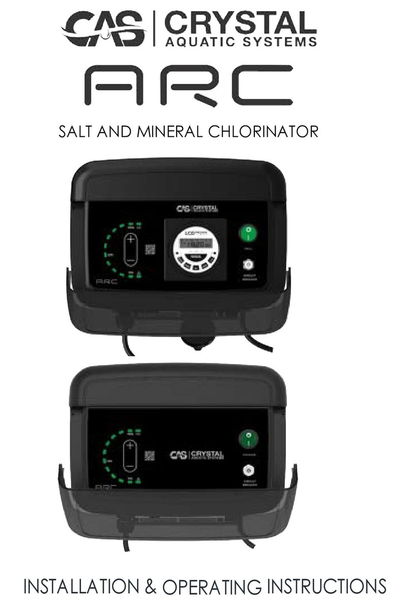
CAS CRYSTAL XR Manual

SALT AND MINERAL CHLORINATOR
INSTALLATION &OPERATING INSTRUCTIONS

TABLE OF CONTENTS
1.
IMPORTANT WARNINGS & SAFETY INSTRUCTIONS
.................3
2.
GENERAL OVERVIEW
..................................................................4
3. POOL PREPARATION
..................................................................6
4. POWER PACK AND CELL INSTALLATION ....................................7
5. POWERPACK OPERATION.............................................................9
6.
TIMER SETTING – N/A in “No Timer” Models
...............................13
7. WATER CHEMISTRY......................................................................15
8. CHLORINATOR MAINTENANCE ..................................................17
9. SYSTEM TROUBLESHOOTING
....................................................19
10. WARRANTY
...............................................................................21
11. TECHNICAL SUPPORT
..............................................................22
12. NOTES
.......................................................................................23

1.
IMPORTANT WARNINGS & SAFETY INSTRUCTIONS
1.1 Important
3
Warnings
This manual contains important information about the installation, operation, and safe use of this
product. This information should be given to the owner and/or operator of this equipment. When
installing and using this electrical equipment, basic safety precautions should always be followed.
Failure to follow safety warnings and instructions in this manual can result in serious injury and/or
damage to your equipment. Read and follow all warning notices and instructions which are
included in this manual.
The Power Supply internally contains live components. There is a danger of electric shock if
opened. If the power cord is damaged then it should be replaced by the manufacturer, their
agent or similar.
1.2 Important Safety Instructions
To reduce the risk of injury, do not permit young children to use this product unless they have been
trained by the person responsible for their safety and they acknowledge their ability to use such
equipment. To reduce the risk of accidents or incidents, service on the unit should only be
performed by your local pool Professional.
1.3 General Warnings
When mixing acid with water, ALWAYS ADD ACID TO WATER. NEVER ADD WATER TO ACID.
DO NOT PLUG UNIT IN IF THE CARTON HAS BEEN WET.
GAS BUILDUP CAN OCCUR WITH IMPROPER WIRING: To reduce the risk of personal injury the Power
Pack is designed so that the Electrolytic Cell will only receive power when the pool pump is on.
Otherwise, dangerous chlorine gas build-up can occur. If the pump is not installed to the AC
Socket (pump outlet) on the Power Pack, then the installer must ensure that the Electrolytic Cell is
never energized when the pool pump is OFF, or water is not flowing through the unit.

2.
GENERAL
4
OVERVIEW
Congratulations on your recent purchase of your XRTM Series Salt Chlorinator.
Please take a moment to read through the entire manual before installing your new unit.
Your chlorinator must be installed and operated as specified.
While every effort has been made to ensure that the information contained in this guide is accurate
and complete, no liability can be accepted for any errors or omissions. Crystal Aquatic Systems
reserves the right to change the specifications of the hardware and software described herein at
any time without prior notice.
Please remember that your XR Series Salt Chlorinator is not designed to chemically maintain your
pool water and keep it balanced, but rather to produce chlorine from a mild salt solution within
the water. We encourage regular water testing, balancing and correction if, and when required to
maintain the recommended balanced levels of your pool water. This is a vital part of a complete
maintenance program and will ensure trouble free performance as well as a healthy and sparkling
clean pool.
The models available are 10, 15, 25, 25LS, 35, 35LS 45 and 55HD in both systems with timer and
pump outlet or without. All are reverse polarity units designed to automatically change direction
every 7 hours. See 5.13 Modifying the Polarity Change Times to change the reversing times from 4
– 10 hours. This change of polarity causes the calcium to dislodge and keep the cell plates clean.
Please note occasional cleaning of the electrode plates may still be necessary in pools with high
or extremely hard calcium.
Thank you again for choosing an XR Series Salt Chlorinator.
We wish you many happy years of swimming in your crystal-clear pool.
XR with timer and pump outlet XR without timer and pump outlet
XR Cell Housing and Cell

2.
GENERAL OVERVIEW
2.1 Recommendations and Helpful
5
Hints
•This manual is available online only, so keep a short cut link to it on your smart devise or
simply scan the QR code on the front sticker.
•Read the manual to optimize and safely operate your chlorinator.
•To stop the sun from removing chlorine, it is recommended to use stabiliser in the swimming
pool.
•Maintain your salt levels between 3500-4000ppm and 1200ppm - 1800ppm for XR25LS and
XR35LS Freshwater/Ultra-Low Salt models, for optimum performance.
•Decrease the output when the water temperature goes down (less than 15°C) to extend cell
life as high chlorine levels are not needed in winter.
•Increase chlorine production when temperature goes up again.
2.2
Contents
2.3 Tools Needed
Wall Mounting
Bracket with Level
Power Pack
2 x 50/40
Reducing Bushes
Cell & Cell Housing
With Unions
Installation &
Warranty Card
2 x Green Wall
Plugs with Screws
Drill with 6mm bit Basic PVC Fittings Hacksaw
Screwdriver
PVC Glue &
Primer

3. POOL
6
PREPARATION
Before operating your XR Series Salt Chlorinator, please read the following:
Check your salt levels in your pool before starting your unit.
Salt levels and mineral levels should ideally be 3000-4000ppm (3500ppm ideal) and 1200ppm -
1800ppm (1500ppm ideal) for XR25LS and XR35LS Freshwater/Ultra-Low Salt models. No more
than 4500ppm for regular models and 2500ppm for Low Salt models. To achieve this salt level
with minerals, you may need to add 20-30% more product to the pool water. Contact your
local pool Professional for further assistance.
Salt levels above 6000ppm may overload the unit and cause excessive heat and void your
warranty. We recommend you lower the output by 10% for every 500ppm over 4500ppm. You
could also drain your pool water to achieve the optimum output. You will save more in
electricity saving than the costs of the water loss.
For all new pool installations please seek advice from your pool builder or your local pool
Professional before adding salt, as some new surfaces request no salt to be added when initially
completed.
NEVER ADD SALT/MINERALS DIRECTLY TO THE SKIMMER BOX. This high concentration of either salt
or minerals will pass through your filtration, pump and other pool equipment.
Handy Tips:
The colder the water the lower your output but this does not mean you need more salt. There
will always be less chlorine demand in colder water.
We recommend adding 3.5kg of pool salt per 1000 litres of pool water, a 50,000lt new pool needs
approximately 175kg of salt. For the FRESHWATER/ULTRA-LOW SALT SYSTEM Models: XR25LS and
XR35LS, we recommend 1.5kg per 1000 litres of pool water.
The unit can operate on mineral/magnesium chloride salts, and you should allow an extra 20-
30% of the product to achieve the correct salt level for these types of salts.
Salt should always be added to the shallow end of the pool and allowed to dissolve. Do not let
the salt settle on the floor of the pool as it may cause damage to the surface. Use your pool
brush to mix the salt into the water.
Running the pump will mix the water and help the salt to dissolve.
Only run the pump in the first 8-12 hours (ensure the cell is switched off) to allow the salt to dissolve.
If you press the Increase Button (+) until all 10 LEDs are ON, then wait 5 seconds and if all 10 LEDs
remain ON then you have enough salt. DO NOT ADD ANY MORE SALT. If only 9 are ON, then
your salt is at 90% of the required level.

4. POWER PACK AND CELL INSTALLATION
4.1 Power Pack
7
Installation
The Salt Chlorinator has an Ingress Protection Rating of IP34 enabling it to be installed outdoors.
Regulations require that the Power Pack shall be installed outside the pool zone. The Power Pack
shall be installed according to AS/NZS 3000 wiring rules.
The Power Pack should be installed in a well-ventilated position ideally away from sunlight and rain
to prolong life and at least 1m above ground to prevent run-off water entry.
Ensure that the Power Pack is not stored near chemicals, fertilisers or in a closed unventilated
shed with similar products as the fumes will cause excessive corrosion and damage to the
internals of the Power Pack and may void warranty.
When mounting the Power Pack on a post it is recommended to install a flat panel at least the
same size to act as a waterproof backing plate.
Mount the Power Pack with the Mounting Bracket, Green Plugs and Screws provided.
The Power Pack should be mounted no further than 1.5 metres from the Chlorinator Cell for ease
of operation.
4.2 Cell Electrode Installation
Connect the Cell Housing horizontally in the return line to the pool (use reducing bushes supplied if
40mm PVC pipe) using high pressure PVC glue. The Cell Housing can be mounted vertically but
provision must be made for a gas trap.
The direction of water flow through the Cell Housing is not critical although we do recommend entry from
the closed end of the Cell Housing and exit from the end closest to the Cell Locking Ring. The reason is to
cause less water hammer over time on the cell plates.
Check that the O-ring is clean, greased with silicone grease (DO NOT use petroleum-based jelly)
and securely located in the Cell Housing.
Ensure Cell Locking Ring is firmly tightened by hand (DO NOT use a tool to tighten).
Connect the cell lead from the Power Pack to the Cell Cap, ensuring a firm fitment to prevent water
entry.
Plug the Power Pack 3 pin plug into a suitable weatherproof RCD protected 10amp outlet.
FOR UNITS WITH A TIMER: Plug the pump into the 3 pin AC Socket located at the bottom of the
Power Pack.

4. POWER PACK AND CELL INSTALLATION
4.3 Installation
8
Diagram
Important Notes:
The pump rating must not exceed 8.7 – 9 amps (depending on your model – see label on Power Pack).
Saltwater may damage electrical components in the Power Pack if splashed on it.
WARNING:
We DO NOT recommend the use of valves on the inlet or outlet of the cell housing. If you do use
a valve, then it is important to ensure that the valve cannot deadhead (lock closed) while the
pump is running. It is the installers responsibility to ensure some form of flow control is installed in
this instance and it disables the pump.
ALWAYS ensure that pipe work and equipment do not allow gases generated from the cell to
collect and build up in any part of the installation.
It is RECOMMENDED that the Cell Housing be installed horizontally to create a natural gas trap
that acts as a safety device. Installation in any other way may cause explosion, injury, or death
if the installer does not allow for gas removal. A venturi pipe is installed/moulded within the Cell
Housing design to eliminate any possible gas build up, although it is always recommended to
ensure proper installation to eliminate this from happening.
The Cell Housing must be installed in the RETURN pipework to the pool. It must always be
installed after the filter, gas heater, solar heating, or heat pump.
DO NOT apply priming fluid to the cell Housing, it is not needed and may react with the plastic.

5. POWERPACK OPERATION
5.1 Timer “MANUAL” Button –
9
n/a in “NO TIMER” Models
This button on the timer moves a black line on the Timer LCD face to the following modes:
•AUTO – the unit is in AUTO mode and the Timer controls the operating hours. See Section 6 for
Timer Setting.
•ON – the unit is ON, and both the pump AC Socket and Cell (providing Cell Switch in ON) will be
powered up.
•OFF – the unit is OFF, and both the pump AC Socket and Cell will be OFF.
5.2 Cell Switch
This switch position determines whether the cell is turned ON or OFF when power is supplied to it
from the timer.
•O – pressing the switch in at the “O” position turns the Cell OFF in all models. For units with a
Timer the pump is controlled by the Timer not the Cell Switch.
•I – pressing the switch in at the “I” position turns the Cell ON in all models. The backlight on the
Cell Switch will light up. For units with a Timer This will only work if the Timer is turned ON.
•Changing Direction – while the unit is running you can change direction by turning OFF the cell
switch, wait 3 seconds then turn it ON again. The direction should change. If it does not, then
repeat this again and it should change direction. Please note, “+/-” LED is ON: cell is in Forward
direction and “+/-” LED is blinking: cell is in Reverse direction.
5.3 Circuit Breaker
The Circuit Breaker only operates the Cell circuit and not the pump circuit. A circuit breaker is an
automatically operated electrical switch designed to protect an electrical circuit from damage
caused by overcurrent, overload, or short circuit. It can be reset by pressing the button in after it
has tripped. It may be damaged if you supply excessively high levels of salt through the cell.
5.4 AC Socket (Pump Outlet) – N/A in “NO TIMER” Models
The AC Socket allows the pump to be electrically operated and controlled by the Power Pack.
WARNING: If you fail to control the pump this way you must install a flow switch mechanism to control
the electrical supply to the Power Pack, to prevent gas build-up if the pump stops or a valve is closed.
5.5 Cell Lead
The proprietary Cell Lead comes complete with moulded gold plated/brass connectors and is
connected to the cell via a watertight plug top.
5.6 Output LEDs
There are ten green chlorine production indicating LED’s. Each indicator corresponds to 10% of
chlorine Production. Each solid LED represents 10% and a blinking LED represents 5%. If you require
55% setting you will have LED 1-5 (i.e., 10% to 50%) is solid ON and LED 6 (60%) will blink.

10
5. POWERPACK OPERATION
5.7 Decrease Button (-)
A single press of this button decreases chlorine production by approximately 5%. To turn OFF
chlorine production it is necessary to press the button several times to make sure all chlorine
indicator LEDs are off.
5.8 Increase Button (+)
A single press of this button increases chlorine production by 5%. When all ten lights are ON the
chlorine production is 100%.
5.9 LED Indicator Chart
A Swing tag is attached to the power pack cell cable for quick reference. There are two LEDs on the
front of the power pack that indicate various states, conditions, and faults. These are as follows:
“+/-“ LED is SOLID GREEN: Chlorinator Cell is outputting in the Forward Direction.
“+/-“ LED is BLINKING GREEN: Chlorinator Cell is outputting in the Reverse Direction.
! WARNING LED is SOLID GREEN: No faults detected, and everything should be functioning
normally.
!WARNING LED is SOLID ORANGE: LOW SALT – have your pool water tested by your local
pool shop; check for calcium build-up on the Cell, insufficient water flow over the Cell, Cell
plates are worn meaning the Cell is reaching the end of its life, check Power Pack Cell Cable
Plug connection to the cell.
! WARNING LED is BLINKING ORANGE: HIGH SALT – have your pool water tested by your
local pool shop; high salt causes excessive heat and wastes electricity. You can save on
power by keeping your salt within range. Turn output down by 10% per 500ppm that the water
is over salted or drain pool water and add fresh water. NOTE: Either of these two actions will
save electricity that would cost more than the cost of the water.
!WARNING LED is SOLID RED: INTERNAL TEMPERATURE TRIP – check that your salt level is not
too high. The fault will reset once the transformer cools down.
!WARNING LED is BLINKING RED: WATER FLOW FAULT – check for air cavities in the cell
chamber causing the gas sensor on the cell cap to not be in the water, raise the speed of the
pump or check that pump is working, remove any air locks, check valves and skimmer/pump
baskets, check flow switch (if applicable). It may take a few minutes for this indicator to reset.
At any stage that the Water Flow LED is ON pressing either the INCREASE or DECREASE buttons
will try to start up the unit again.

11
5. POWERPACK OPERATION
5.10 Chlor Boost
The XR Series Salt and Mineral Chlorinator can be set to “Chlor Boost” (Chlorine Boost) for 24
hours by default and automatically sets the chlorine output to 100% during that time. To enter
chlor boost hold the “+” and “-“ buttons in simultaneously for approximately 3-5 seconds.
After releasing the buttons, the LED’s 2 and 4 will flash on for 5 seconds to indicate the unit
has entered “Chlor Boost”. It you wish to change the “Chlor Boost” time setting you can do so
by pressing the “+” or “-“ buttons this will cause the unit to cycle through settings.
Pressing “+” will have the effect of increasing the hours from 24 up to 28, 32, 36 and back to 4,
8, 12, 16, 20, 24 hours respectively. Pressing “-“ will have the effect of decreasing the hours
from 24 to 20, 16, 12, 8, 4 and then back up to 36, 32, 28 and 24 hours respectively.
LED’s 1 through to 10 will turn on for 5 seconds and then off for 1 second to indicate that
“Chlor Boost” has been activated.
To turn off “Chlor Boost” at any time before its running time, press and hold the “+” and “-“
buttons together for 3-5 seconds. The unit will indicate that it is deactivating “Chlor Boost” by
causing the “flow fault” LED (LED 12) to flash three times and then the unit will revert to its
normal function with LED indicating regular output.
5.11 Start Up Procedure
•Plug the Power Pack 3 pin plug into a suitable weatherproof RCD protected 10amp outlet
and then plug the pump into the socket at the base of the XR Chlorinator.
•Ensure the Cell is connected and make sure the Cell Cable is inserted fully into the
connections on the Cell Cap.
•Turn the 10-amp wall outlet supply switch to “ON”.
•Ensure the Cell Switch is turned ON and the timer is in ON mode.
•The pump should start up and prime.
•LED’s 1,2 and/or 3 will light up for 0.5 seconds.
•The last saved output set point is displayed on the ten output LED’s.
•The Indicator LED should be SOLID GREEN.
•Either the “Forward” or “Reverse” LED status will be displayed on the “+/-” LED.
•Ensure that once you have performed the initial start-up you reset the timer to “AUTO”
mode.
•Run the chlorinator for 6-10 hours per day in the summer and 3-6 hours per day in the winter.
5.12 Temporary Change of Polarity
•Start with the unit “ON” and identify if it is operating in the “Forward” or “Reverse” direction.
•Turn the unit OFF at the Cell Switch.
•Wait 3-5 seconds and then turn the Cell Switch ON.
•The polarity should change and the direction LED “+/-” should display the opposite direction.
•Is this does not work then perform the OFF – WAIT 3 SEC – ON process again.
•The unit will stay in this direction for 2 minutes and then revert to the original direction.
The polarity will change every 7 hours in normal operation (factory set). This polarity change
can be permanently set to between 4 and 10 hours if required. Only lower this time if the Cell
is not cleaning (mainly due to very high calcium levels).

5. POWERPACK OPERATION
5.13 Modifying the Polarity Change
12
Times
IMPORTANT: The platinum coating on the cell plates may not last as long with quicker change
over times as a percentage of wear on the coating is related to the number of polarity
changes.
To Permanently set the polarity change frequency, follow the directions below:
•Start with the unit “OFF”.
•Press and hold the “DECREASE” button.
•Turn the unit “ON”.
•Release the button and the selected reversing time will display. The default will be set to 7
hours, and LED 7 will display. If LED 4 displays, this indicates that the reversing time is 4
hours and this can be increased by increments of 1 hour which will correspond with the
number of LED’s displayed. If LED 1, 2 and 3 display this means the reversing period is 10
hours.
•To change the reversing hours, press the “DECREASE” or “INCREASE” button to switch from
one reversing hour to another.
•Once you have selected the reversing time you require, turn the unit “OFF”. The new
setting will apply next time you turn the unit “ON”.

6.
TIMER SETTING –
13
N/A in “No Timer” Models
Summer Settings
Ideally, run for 4 hours in the morning (6am-10am) and 4 hours in the evening (4pm-8pm). For
a smaller pool you can run less hours. In extreme weather it may be necessary to run longer
hours. Contact your local pool Professional for further assistance.
Winter Settings
In winter you should lower your running time by up to 50% of your summer setting depending on
your free chlorine levels. Ideally, you should run 2-3 hours in the morning and 2-3 hours in the
evening. This preserves and extends the life of your equipment.
IMPORTANT: The Timer Switch will override the timer when it is in the Manual position. For timer
settings to control the unit the Timer Switch needs to be in the AUTO position.
Setting your XR Timer
These are the functional Buttons and display on your timer:
TIMER Program review and
setting programs
MANUAL To select "ON/AUTO/OFF"
Modes
CLOCK To adjust current DAY
and TIME
DAY To adjust the day of the
week
HOUR To adjust the hour
MIN To adjust the minute
Reset Timer's settings
LED To indicate ON/OFF
status
How to reset the Timer & Perform Software Version Check
Press the button with a sharp-pointed tool for about 3 seconds to reset the Timer before programming. Resetting the Timer will achieve
the following:
1 It shows the software version.
2 It resets the TIMER mode back to 2-7 (default setting).
3 It resets the TIME and DAY of the clock to default value (i.e.: Mo 00:00) and clears all
timer events.
Setting Day and Time
This Timer has a 24-hour clock. Days, Hours and Minutes are individually set by pressing a combination of the CLOCK button and the
corresponding DAY/HOUR/MIN button, as follows:

6.
TIMER SETTING –
14
N/A in “No Timer” Models
4 DAY: Press and Hold the CLOCK button, then repeatedly press the DAY button until the
correct day is displayed.
5 HOUR: Press and Hold the CLOCK button, then repeatedly press the HOUR button until
the correct hour is displayed.
6 MINUTE: Press and Hold the CLOCK button, then repeatedly press the MINUTE button until
the correct minute is displayed.
Setting Event #1
7 Press the TIMER button once, and the timer displays "1 ON" plus a series of --:--
Note: This represents the "Program #1 "ON" time which is about to be saved.
8
Press the DAY button once, and all the days of the week will appear at the top of the
screen, and "0:00" will appear as the time.
Press the HOUR button until the LCD screen displays the exact hour required for the system
to turn ON.
Press the MIN button until the LCD screen displays the exact minute required for the system
to turn ON.
9
Press the TIMER button once again, and the timer displays "1" and "OFF" plus a series of --
:--.
This represents the "Program #1 "OFF" time which is about to be saved.
Repeat step 2 above to set your required OFF time.
Setting Event #2
Note: If you do not want to use timer 2, then leave both ON and OFF at 00:00.
10 Press the TIMER button once again, and the timer displays "2 ON" plus a series of --:--.
Note: This represents the "Program #2 "ON" time which is about to be saved.
11 Follow steps 11 and 12 to set your required "ON"
and "OFF" times.
12 Press the CLOCK button, and your settings are saved, and the real-time is displayed.
13 Press the MANUAL button until the solid line on the lower part of the LCD is above the AUTO label on the timer front. Your TIMER is
now set.
MANUAL ON / TIMER AUTO / OFF MODE
This setting is displayed above the MANUAL button and can be changed by pressing the MANUAL
button. The bar on the LCD moves as follows: AUTO OFF AUTO ON AUTO
OFF. This sequence can start from anywhere.
ON-MODE: The Timer is always ON. The user must press the MANUAL button to turn the Timer OFF or take it to AUTO mode. The LCD screen will
not switch off when the Timer switches off at the set time.
OFF-MODE: The Timer is always OFF. The Timer will not switch on at the next set time. The user has to manually press the MANUAL button to take
the Timer to AUTO or ON mode.
AUTO-MODE: The Timer will switch ON and OFF on the set time frames. Outside the set timeframe, the Timer is OFF but in AUTO mode.
DISPLAY OFF
If the screen stays idle for 30 seconds during TIMER adjustment, it goes to default screen. If the TIMER remains idle for 60 seconds in default
screen, the display will switch OFF. This only happens when the main power to the TIMER is off, and the TIMER is being powered by the internal
battery.
REPLACING THE BATTERY
NOTE TO ELECTRICIAN: The power supply requires tools to open and access the timer battery case. The
battery is a 3V Lithium CR2032 battery.
The battery life is expected to be over 5 years and the timer will work, even with a flat battery, provided
there is mains power to the timer.
WARNING: KEEP REPLACED BATTERY OUT OF REACH OF CHILDREN. Swallowing can lead to chemical
burns, perforation of soft tissue, and death. Severe burns can occur within 2 hours of ingestion. Seek
medical attention immediately.
CAUTION: THERE IS A RISK OF EXPLOSION IF BATTERY IS REPLACED BY AN INCORRECT TYPE.
DISPOSE OF USED BATTERIES ACCORDING TO THE INSTRUCTIONS ON REPLACEMENT BATTERY PACK

7. WATER
15
CHEMISTRY
The XR Salt Chlorinator unit is designed for use with swimming pool water balanced in
accordance with the Langelier Saturation Index with a pH range of 6.8-7.8.
As previously advised, for best performance and operation of your XR Salt Chlorinator unit,
certain water balances must be maintained within your swimming pool. Have your water tested
regularly. Transport the test water in an opaque container and have the test done as soon as
possible for best results.
7.1 Chlorine
Measurement Interval: Once a week
Ideal Chlorine (Free Chlorine) Levels: 1-3ppm (1-3mg/L) and no more than 4ppm (4mg/L).
Adjust the chlorine output by pressing [+] to increase the required output set point in 15%
increments up to 100%. Pressing [-] will decrease the output in 15% increments to 0%. Running
the unit for longer or shorter hours can achieve the same result.
7.2 Salt
Measurement Interval: Every 4-6 weeks
Ideal Salt Levels: 3500-4000ppm and no more than 4500ppm. For the FRESHWATER/ULTRA- LOW
SALT SYSTEM Model: XR25LS and XR35LS, the ideal Salt reading is 1200-1800ppm (1500ppm
ideal).
Although salt is not consumed by the Chlorinator, salt is lost during backwashing, pool overflow,
splashing and on bathers that use it. The correct salt level allows for the most efficient
production levels and electricity consumption.
The salt level SHOULD NOT go below 3000ppm or 1200ppm for the XRC25LS and XR35LS models.
Operating the unit with too little salt in the pool will cause damage to your Cell.
Salt is the essential element by which your unit operates. Not enough salt means not enough
chlorine - this simple rule governs the total operation of your XR Series Salt Chlorinator unit, and
insufficient salt will damage your Cell. Use Ultrafine Salt or Premium Salt to keep optimum salt
levels.
The unit will operate with good stability on higher salt levels, but it is still advisable to run at the
correct level to prevent damage. Salt levels above 4500ppm may overload the unit and cause
excessive heat.
NEVER ADD SALT DIRECTLY TO THE SKIMMER BOX. This high concentration of salt will pass through
your filtration, pump, and other pool equipment.
HANDY TIP: The colder the water, the lower your output, but this does not mean you need more
salt. There will always be less chlorine demand in colder water.
We recommend 3.5kg per 1000 litres of pool water and a 50,000lt new pool needs
approximately 175kg of salt. For the FRESHWATER LOW SALT SYSTEM Models: XR25LS and XR35LS,
we recommend 1.5kg per 1000 litres of pool water.
The unit can operate on mineral/magnesium chloride salts, and you should allow an extra 20-
30% more product to achieve the correct TDS for your unit to run efficiently.
Salt should always be added to the shallow end of the pool and allowed to dissolve. Do not let
the salt settle on the floor of the pool as this may cause damage to the surface. Use your pool
brush to mix the salt into the water.
Running the pump will mix the water and help the salt to dissolve.
Low salt levels (<1000ppm) will destroy the coating on the Cell and void the warranty.

7. WATER CHEMISTRY
7.3
16
pH
Measurement Interval: Once a week
Ideal pH Levels: Concrete Pools: 7.4 - 7.6
Fibreglass/Vinyl Pools: 7.2 - 7.4
A pH of 8.0 results in your chlorine only been about 26% efficient, which is why it is critical to keep
your pH in range.
A correct pH level must be maintained to prevent problems such as black spot, staining, cloudy
water, etc. An incorrect pH level can damage the surface finish and walls of your pool.
When pH is high you can add Hydrochloric Acid to lower the pH.
When pH is low you can add pH Increaser - sodium bicarbonate (soda ash) to increase the pH.
7.4 Total Alkalinity
Measurement Interval: Every 4-6 weeks
Ideal Total Alkalinity Levels: Concrete Pools: 80 - 150ppm
Fibreglass/Vinyl Pools: 80 - 120ppm
Total Alkalinity should not be confused with pH, although the two are closely related. Total
Alkalinity determines the speed and ease of pH change, it is measured in ppm. You should use
a test kit which includes a test for Total Alkalinity. Low Total Alkalinity can cause unstable pH
levels. This causes an inability to keep the pH constant and may cause staining, etching and
corrosion of metals. High Total Alkalinity will cause constantly high pH levels.
When Total Alkalinity is high you can add Hydrochloric (a little at a time) to lower the Total
Alkalinity. When Total Alkalinity is low you can add pH Increaser - sodium bicarbonate to raise
the Total Alkalinity.
7.5 Calcium Hardness
Measurement Interval: Every 3 months
Ideal Calcium Hardness Levels: Concrete Pools: 250 - 300ppm
Fibreglass/Vinyl Pools: 150 - 190ppm
In addition to pH and Total Alkalinity, Calcium Hardness must be kept in balance so that your
pool water does not become too corrosive or end up scaling the surface of your pool. These
conditions are symptoms or swimming pool water that is unbalanced.
7.6 Stabiliser
Measurement Interval: Every 4-6 weeks
Ideal Stabiliser Levels: 30 - 60ppm
The importance of pool Stabiliser cannot be over emphasised. It is essential in helping retain
chlorine in your pool. Chlorine is rapidly dissipated by sunlight and the use of Stabiliser will
reduce this dissipation dramatically. Without Stabiliser, it may be necessary to run the unit for
longer hours.
THE MOST IMPORTANT NOTICE AND WARNING:
Only add chemical in the method and quantities as indicated on the packaging provided or
advised by your local pool Professional. Also, if in doubt of any results you achieve then do not
hesitate to consult with your local pool Professional.

8
17
. CHLORINATOR MAINTENANCE
Maintenance of your XR Series Salt Chlorinator is simple. Your unit must be one of the most
productive pieces of equipment on your swimming pool, so it requires some basic maintenance.
While water chemistry will always be the most important form of maintenance there are also
other hints and pointers to take note of.
DO NOT cover the Power Pack with towels or similar. There are vents that could be closed and
these need air to keep the unit cool.
To extend the life of your unit we always recommend installation in an undercover area away
from the elements.
Placing the unit in a closed shed or similar environment with chemicals, fertilisers and other
corrosives will damage the unit and could void your warranty.
Always keep the chlorinator off whilst backwashing your sand filter. Please remember to turn it
on once backwash is done and return the unit to AUTO mode if using the timer model.
Check that the plug connections on the Cell and the base of the unit are tight and are in
sound condition at least once a year.
8
.
1 Inspecting and Cleaning the Cell Electrode
Reverse Polarity cells should not normally require cleaning, however, in areas with very hard
water all calcium may not be removed. A calcium deposit might form on the lower areas of
the cell, the sensor, or the sides of the cell plates. This will affect the operation of your
chlorinator; however, you can use Cell Cleaner to clean the Cell.
All salt chlorinator cells must be cleaned before scale/calcium builds up to the point where
the electrode gaps in the Cell are bridged. If the Cell has an excessive calcium deposit, this
may damage the electrode coating, as the bridging causes a rubbing on the place coating,
and this will affect the operation.
Check the Cell to prevent the accumulation of pool debris that for any reason may have by-
passed the pool filter, particularly after backwashing.
Check that the O-ring is clean, greased with silicone grease (DO NOT use petroleum-based
jelly) and securely located in the Cell Housing.
For cleaning, please follow these steps:
Switch the timer from “AUTO” to “OFF” as this ensures the pump, and the unit will not turn on.
Unscrew the Cell Locking Ring and remove the electrode for inspection. If calcium build-up is
present, immerse the electrode in Cell Cleaner.
A solution can be made by mixing 1-part hydrochloric acid to 10 parts of water. If excessive
build up is present a stronger solution may be used to remove the calcium.

8.
18
CHLORINATOR MAINTENANCE
Using 5 parts of water will make a more aggressive solution but will not damage the Cell. You
can use Cell Cleaner and if you do then follow the instruction supplied.
Allow the cleaning solution to dissolve the calcium deposits for about 10 minutes. Dispose of
the cleaning solution at an approved Council Depot and never into storm water or sewage
drains.
HANDY TIP:
Returning this mix to your pool only returns the calcium you just removed, so you may be better
off reusing the solution until exhausted then disposing of it. Always store this solution in a safe
method as advised on the container.
Do not scratch or bend the electrode plates in the Cell Housing. Ensure that the O-ring is
clean, greased and properly seated.
Rinse the electrode in clean water and re-fit the electrode in the Cell Housing, ensuring that
the Cell Locking Ring is hand tight and secure.
When mixing acid with water, ALWAYS ADD ACID TO WATER. NEVER ADD WATER TO ACID.
Eye Protection, mask and gloves should be worn when cleaning the cell.
8.2 Inspecting the Power Pack
Little or no maintenance is normally required with the XR Series Salt Chlorinator Power Pack.
Ensure the Power Pack 3 pin plug plugs into a suitable weatherproof RCD protected 10amp
outlet. Ensure that the pump plugs into the 3 pin AC Socket located at the bottom of the Power
Pack. Check all plugs and cords for damage. If damaged, then it should be replaced by the
manufacturer, their agent or similar qualified person, to avoid a hazard.
If the chlorinator is to be hard wired, then a qualified electrician must complete the installation.
The XR Series Salt Chlorinator Power Pack has air vents to allow internal components to remain
cool in hot weather. The XR Series Salt Chlorinator has a special oil spray applied to the inside of
the unit during production to stop the insects from entering the unit. To help assist in keeping the
insects away, apply a surface spray periodically on the wall or post that the unit is mounted on.
DO NOT spray directly into the Power Pack and make sure the power is off when you use a spray.
Allow adequate time for the spray to dry before turning power on again.

9
. SYSTEM
19
TROUBLESHOOTING
If you suspect for any reason your XR Series Salt Chlorinator is not performing or running as it should be,
here are some handy troubleshooting tips that may assist you.
Fault Indication Potential Cause Remedy
9.1 NO OPERATION AT
ALL – NO LIGHTS
Not plugged into power
point or power point not
turned on
Check that unit power cord goes
into wall outlet and outlet is turned
on.
Plugged into power point
but still no power
Test wall outlet with a working
appliance.
9.2 POWER AND
DIRECTION LIGHTS
ON – NO OUTPUT
LIGHTS
Cell is not connected Check brass pins and Cell
connections and tighten if
necessary.
Output set too low Adjust output with the Output (+)
button and lights should increase.
Excessive build up in the Cell See cleaning of the cell electrode
(Sec 8.1).
Low salt level Check salt level (Sec 7.2).
The cell could be
damaged or at the end of
its life
Damaged coating will reduce cell
life and reduce output.
If all conditions are correct, then
Cell could be at the end of its life.
Faulty control PCB or
Faulty Main Power supply
PCB
Call for service.
9.3 WATER FLOW LED
IS BLINKING RED
Low or no water flow Ensure sufficient water flows
through chlorinator cell.
Check that the pump is on and
running.
Look for air pocket – perform
backwash if needed.
Check skimmer and pump baskets
are clean and securely tightened.
Check for suction leaks.
Seek advice from a pool
professional for any of the above.
Cell is not connected Check Cell and brass pins and cell
connections and tighten if needed.
9.4 LOW OUTPUT
READING
Output set too low Adjust output with the (+) button
and output lights should increase.
Low salt level Check salt level (sec 7.2).
Buildup of calcium on the
Cell plates
Calcium acts as an insulator and
needs to be removed.
See Cleaning of Cell Electrode (Sec
8.1).
Water temperature is low Winter water temperature can be
very low. For every 1°C below 28°C
the output can drop 2-3%.
Insufficient water flow
through
the Cell
Check water flow and ensure a
full chamber of water is passing
over the Cell. You may need to
backwash your filter.

9. SYSTEM
20
TROUBLESHOOTING
The Cell could be
damaged or at the end
of its life
Damaged coating will reduce cell
life and reduce output.
If all conditions are correct, then
Cell could be at the end of its life.
Level low in one direction
but OK in the other
Cell may need cleaning (Sec 8.1), or
the Cell may have run its life in one
direction.
9.5 WARNING LED IS
SOLID RED – INTERNAL
TEMPERATURE TRIP
Salt level may be too high Check Salt guide (Sec 7.2). The fault
will reset once the transformer cools
down.
9.6 WARNING LED IS
BLINKING ORANGE –
HIGH SALT WARNING
Salt level is too high Check salt guide (Sec 7.2).
9.7 WARNING LED IS
SOLID ORANGE – LOW
SALT WARNING
Salt level is too low Check salt guide (Sec 7.2).
9.8 CELL FORWARD LED IS
ONLY “SOLID” GREEN
OR ONLY “FLASHING”
IE- POWER PACK
ONLY WORKS IN ONE
DIRECTION
Faulty Main Power
Supply PCB or Relay
See Changing polarity (Sec 5.12).
If unit still only operates in one
direction contact service
department.
9.9 POOL PUMP OUTLET
NOT FUNCTIONING
PROPERLY OR PUMP
ALWAYS ON
Pump not plugged into
chlorinator
Check that pump is plugged into
the bottom of the power pack
and not directly into the wall
outlet.
9.10 CELL NOT CLEANING,
EXCESSIVE CALCUIM
BUILD UP ON CELL OR
POWER PACK NOT
CHANGING
DIRECTION
Excessively high
calcium, change of
direction time set too
high or faulty Main
Power Supply PCB
1. See calcium hardness test (Sec
7.5) and adjust water accordingly.
2. Manually try reverse direction
(Sec 5.11 – Temporary Change of
Polarity). Failure for this to work could
indicate a faulty Main Power Supply
PCB – contact service department.
3. Decrease the cell cleaning time
(Sec 5.12)
9.11 LOW OR NO
CHLORINE OUTPUT
Unit not working correctly Go through troubleshooting from
9.2.
Unit not set correctly Check the output settings.
Excessive calcium build-
up on the Cell plates
Calcium acts as an insulator and
needs to be removed.
See cleaning of Cell Electrode.
Salt level is too low Check salt guide (Sec 7.2).
pH is too high Check pH guide (Sec 7.3).
Stabiliser is too low Check Stabiliser (Sec 7.6).
Cell at the end of its life If full output is not reached, then it
could be a failing Cell.
Table of contents
Other CAS Water Filtration System manuals
Popular Water Filtration System manuals by other brands

Culligan
Culligan Aqua-Cleer Installation, operation & service instructions with part list

BWT
BWT COVERDECK AX-IN Installation and maintenance instructions

Midea
Midea JL1643S-UF user manual

Evolution Aqua
Evolution Aqua eazypod Installation & operating instructions

Spectrum
Spectrum PTL RO System installation instructions

AOX
AOX COMPAC Series user manual