Cascade Sciences CVO-5 User manual

Vacuum Ovens
Installation - Operation Manual
CVO-5 CVO-5-2 CVO-10

2 | Page
cascadesciences.com |Tel. 503 847-9047
The CVO-10 and CVO5-2 require a 220 – 240-volt power supply outlet to plug into (NEMA 6-15R).
The CVO-5 requires a standard 110 – 120-volt power supply outlet to plug into (NEMA 5-15R).
Warning:This product contains chemicals, including Triglycidyl Isocyanurate, known to the State of
California to cause cancer as well as birth defects or other reproductive harm. For more information
go to www.P65Warnings.ca.gov.
¡Advertencia! Este producto contiene sustancias químicas, incluido el triglicidil isocianurato, que el
estado de California sabe que causa cáncer, así como defectos de nacimiento u otros daños
reproductivos. Para obtener más información, visite www.P65Warnings.ca.gov.
Avertissement!Ce produit peut vous exposer à des produits chimiques, dont l'isocyanurate de
triglycidyle, reconnu par l'État de Californie pour provoquer le cancer, des anomalies congénitales
ou d'autres problèmes de reproduction. Pour plus d'informations, visitez le site
www.P65Warnings.ca.gov

3| Page
cascadesciences.com |Tel. 503 847-9047
Vacuum Ovens
CVO-10, CVO-5-2: 220 – 240 Voltage
CVO-5: 110 – 120 Voltage
Installation and Operation Manual
Part Number (Manual): 4861833
Revision: July 15, 2019

4 | Page
cascadesciences.com |Tel. 503 847-9047
TABLE OF CONTENTS
CERTIFICATIONS .......................................................................................................................................................7
UNIT SPECIFICATIONS ............................................................................................................................................ 9
Temperature Performance ..................................................................................................................................................9
Power........................................................................................................................................................................................ 11
Weight....................................................................................................................................................................................... 11
Dimensions.............................................................................................................................................................................. 11
Capacity .................................................................................................................................................................................. 12
Shelf Capacity by Weight................................................................................................................................................... 12
INTRODUCTION .......................................................................................................................................................13
Read this Manual.................................................................................................................................................................. 13
Contacting Assistance ........................................................................................................................................................ 13
Engineering Improvements................................................................................................................................................ 13
Vacuum Supply Required .................................................................................................................................................. 14
Gaskets ................................................................................................................................................................................... 14
RECEIVING YOUR UNIT ..........................................................................................................................................15
Inspect the Shipment........................................................................................................................................................... 15
Orientation Images .............................................................................................................................................................. 16
Recording Data Plate Information................................................................................................................................... 21
INSTALLATION ........................................................................................................................................................ 23
Installation Procedure Checklist ..................................................................................................................................... 23
Required Ambient Conditions.......................................................................................................................................... 24
Required Clearances.......................................................................................................................................................... 24
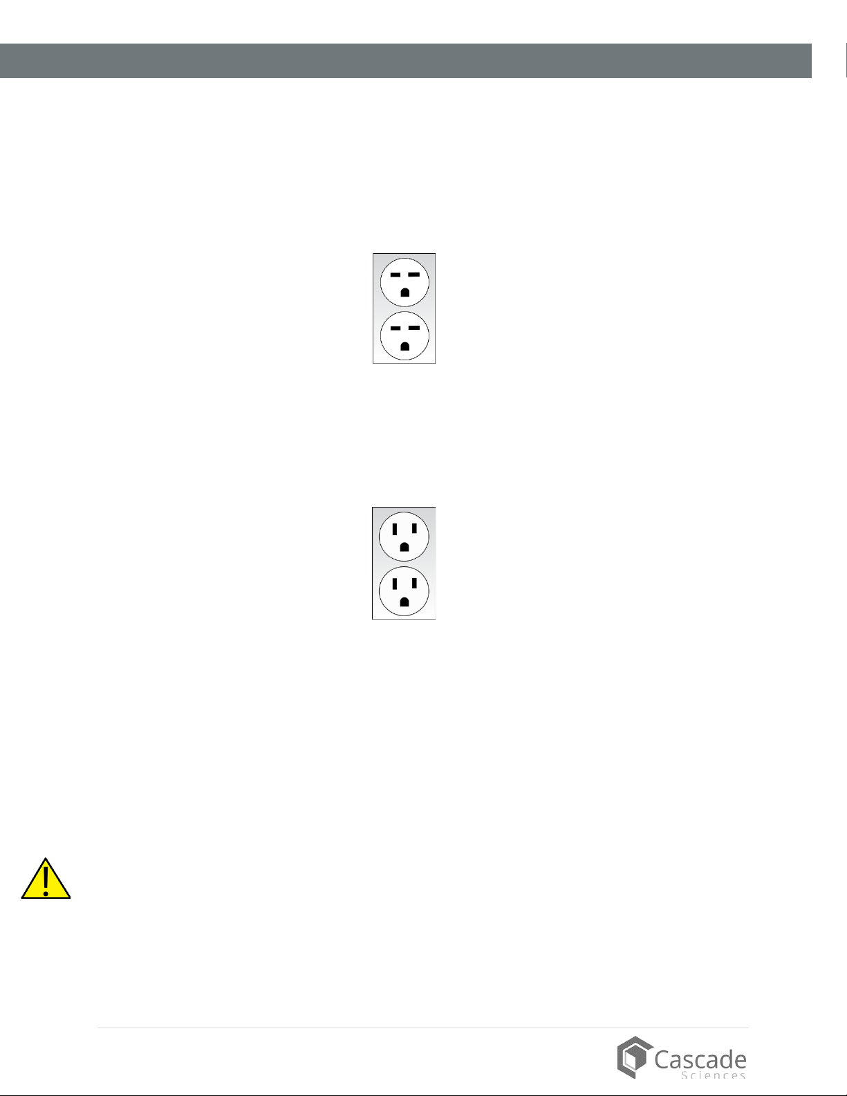
Power Source Requirements ........................................................................................................................................... 25
General Power Safety ........................................................................................................................................................ 26
Lifting and Handling ............................................................................................................................................................27
Removing from the Pallet...................................................................................................................................................27
Leveling.................................................................................................................................................................................. 28
Install the Oven .................................................................................................................................................................... 29
Installation Cleaning........................................................................................................................................................... 29
Install the Shelving.............................................................................................................................................................. 30
Connect to the Vacuum Supply ...................................................................................................................................... 32
Connect to a Gas Backfill Supply ................................................................................................................................... 34
GRAPHIC SYMBOLS ............................................................................................................................................... 35
CONTROL OVERVIEW ............................................................................................................................................ 37
OPERATION...............................................................................................................................................................41
Safety Guidelines ................................................................................................................................................................. 41
Operating Precautions....................................................................................................................................................... 42
Theory of Operation ........................................................................................................................................................... 43
Put the Oven into Operation ............................................................................................................................................ 45
Change the Unit of Measurement ...................................................................................................................................47
CVO-10 – Pumping Down and Backfilling.................................................................................................................... 48
CVO-5s – Pumping Down and Backfilling ................................................................................................................... 49
Set the Temperature Setpoint ......................................................................................................................................... 50
Heat the Oven....................................................................................................................................................................... 51
Using the Timer.................................................................................................................................................................... 52
Backfilling Temperature Display Pause........................................................................................................................ 53
Door Heating Interruption................................................................................................................................................. 53
Data Ports.............................................................................................................................................................................. 53
Set the Date and Time....................................................................................................................................................... 54
CVO-10 – Shelf Spring Color Change ........................................................................................................................... 55
Oven Cooldowns ................................................................................................................................................................. 55
USER MAINTENANCE............................................................................................................................................. 57

5| Page
cascadesciences.com |Tel. 503 847-9047
Cleaning and Disinfecting..................................................................................................................................................57
Maintaining Atmospheric Integrity ................................................................................................................................. 58
Gaskets .................................................................................................................................................................................. 59
Electrical Components....................................................................................................................................................... 60
Vacuum Pump Maintenance............................................................................................................................................ 60
REPLACEMENT PARTS ...........................................................................................................................................61

6 | Page
cascadesciences.com |Tel. 503 847-9047
TABLE OF CONTENTS

7| Page
cascadesciences.com |Tel. 503 847-9047
CERTIFICATIONS
This certificate satisfies NRTL safety requirements
TÜV SÜD CUE
Certificate Number: U8 064872 0095
These units are CUE listed by TÜV SÜD as vacuum ovens for appropriate professional, industrial, or
educational use. TÜV SÜD America Inc. is an OSHA recognized NRTL and a Standards Council of
Canada accredited certification body.
The units have been tested to the following requirements:
CAN/CSA-C22.2 No. 61010-1:2012 + UPD N0. 1:2015-07 +
UPD No. 2:2016-04
CAN/CSA C22.2 No. 61010-2-010:2015
UL 61010-1:2012/R:2016-04
UL 61010-2-010:2015
EN 61010-1:2010
EN 61010-2-010:2014

8 | Page
cascadesciences.com |Tel. 503 847-9047
CERTIFICATIONS

9| Page
cascadesciences.com |Tel. 503 847-9047
UNIT SPECIFICATIONS
Please refer to the oven data plate for individual electrical specifications.
Technical data specified applies to units with standard equipment at an ambient temperature of 25°C
±3° (77°F ±5.4°) and at nominal voltage. The temperatures specified are determined in accordance
with factory standards respecting the recommended wall clearances of 10% of the height, width, and
depth of the inner chamber. All indications are average values, typical for units produced in the
series. We reserve the right to alter technical specifications at all times.
TEMPERATURE PERFORMANCE
Operating Range
Model Fahrenheit Celsius
CVO-10 Ambient +26°to 302°F Ambient +14.4°to 150°C
CVO-5 Ambient +26°to 302°F Ambient +14.4°to 150°C
CVO-5-2 Ambient +26°to 302°F Ambient +14.4°to 150°C
Temperature Uniformity
Model @ 105°F @ 200°F @ 300°F
CVO-10 ±2.0°F ±5.5°F ± 8.0°F
CVO-5 ±2.0°F ±3.6°F ±5.5°F
CVO-5-2 ±2.0°F ±3.6°F ±5.5°F
Model @ 40°C @ 90°C @ 150°C
CVO-10 ±1.0°C ±3.0°C ± 4.5°C
CVO-5 ±1.0°C ±2.0°C ±3.0°C
CVO-5-2 ±1.0°C ±2.0°C ±3.0°C

10 | Page
cascadesciences.com |Tel. 503 847-9047
SPECIFICATIONS
Temperature Stability
Model @ 105°F @ 200°F @ 300°F
CVO-10 ±0.2°F ±0.4°F ±0.2°F
CVO-5 ±0.2°F ±0.4°F ±0.2°F
CVO-5-2 ±0.2°F ±0.4°F ±0.2°F
Model @ 40°C @ 90°C @ 150°C
CVO-10 ±0.1°C ±0.2°C ±0.1°C
CVO-5 ±0.1°C ±0.2°C ±0.1°C
CVO-5-2 ±0.1°C ±0.2°C ±0.1°C
Heat Up Time from Ambient (77°F / 25°C)
Heating times will vary based on the starting chamber temperature.
Model To 105°F (40°C) To 200°F (90°C) To 300°F (150°C)
CVO-10 42 Minutes 106 minutes 175 minutes
CVO-5 60 Minutes 126 minutes 180 minutes
CVO-5-2 60 Minutes 126 minutes 170 minutes
Cool Down Times
Approximate times with the chamber under vacuum. Cooling rates can be influenced by ambient
conditions.
Model From 105°F (40°C)* From 200°F (90°C)** From 300°F (150°C)**
CVO-10 330 Minutes 305 minutes 420 minutes
CVO-5 345 Minutes 285 minutes 335 minutes
CVO-5-2
300 Minutes 265 minutes 460 minutes
*To 86°F (30°C)
** To 122°F (50°C)

11 | Page
cascadesciences.com |Tel. 503 847-9047
SPECIFICATIONS
POWER
Model AC Voltage Amperage Frequency Phase
CVO-10 220 – 240 13.0 50/60 Hz 1
CVO-5 110 – 120 14.0 50/60 Hz 1
CVO-5-2 220 – 240 7.0 50/60 Hz 1
WEIGHT
Model Shipping Net Weight
CVO-10 775 lb / 352 kg 663.0 lb / 301.0 kg
CVO-5 449 lb / 204 kg 360.0 lb / 163.3 kg
CVO-5-2 449 lb / 204 kg 360.0 lb / 163.3 kg
DIMENSIONS
By Inches
Model Exterior W × D × H Interior W × D × H
CVO-10 42.0 x 40.2 x 67.4 in 28.0 x 24.0 x 24.0 in
CVO-5 25.0 x 33.1 x 31.3 in 18.0 x 24.0 x 18.0 in
CVO-5-2 25.0 x 33.1 x 31.3 in 18.0 x 24.0 x 18.0 in
By Millimeters
Model Exterior W × D × H Interior W × D × H
CVO-10 1067 x 1021 x 1712 mm 711 x 609 x 609 mm
CVO-5 635 x 841 x 795 mm 457 x 609 x 457 mm
CVO-5-2 635 x 841 x 795 mm 457 x 609 x 457 mm

12 | Page
cascadesciences.com |Tel. 503 847-9047
SPECIFICATIONS
CAPACITY
Model Cubic Feet Liters
CVO-10 9.3 263.0
CVO-5 4.5 127.0
CVO-5-2 4.5 127.0
SHELF CAPACITY BY WEIGHT
Model Per Shelf Total
CVO-10 50.0 lb / 22.7 kg 225.0 lb / 102.0 kg
CVO-5 50.0 lb / 22.7 kg 225.0 lb / 102.0 kg
CVO-5-2 50.0 lb / 22.7 kg 225.0 lb / 102.0 kg

13 | Page
cascadesciences.com |Tel. 503 847-9047
INTRODUCTION
READ THIS MANUAL
Failure to follow the guidelines and instructions in this user manual may create a protection
impairment by disabling or interfering with the unit safety features. This can result in injury or death.
Before using the unit, read the manual in its entirety to understand how to install, operate, and
maintain the unit in a safe manner. Ensure all operators are given appropriate training before the unit
begins service.
Keep this manual available for use by all operators.
Intended Applications and Locations
CVO vacuum ovens are engineered for drying, curing, and baking applications under vacuum in
professional, industrial, and educational environments. The ovens are not intended for use at
hazardous or household locations.
CONTACTING ASSISTANCE
Please have the following information ready when calling or emailing Technical Support: the model
number and the serial number (see page 21).
Phone: 503 847-9047
Cascade Sciences
6725 NE Evergreen Pkwy
Ste 106
Hillsboro, OR 97124
ENGINEERING IMPROVEMENTS
Cascade Sciences continually improves all of its products. As a result, engineering changes and
improvements are made from time to time. Therefore, some changes, modifications, and
improvements may not be covered in this manual. If your unit’s operating characteristics or
appearance differs from those described in this manual, please contact your oven dealer or
customer service representative for assistance.

14 | Page
cascadesciences.com |Tel. 503 847-9047
INTRODUCTION
VACUUM SUPPLY REQUIRED
CVO ovens require a vacuum supply source, which must be purchased separately from
the oven. Please see the Cascade Sciences website for pumps and vacuum system
accessories suitable for your application.
cascadesciences.com/vacuum-pumps
GASKETS
CVO-10
The oven comes with cured silicone gaskets built into the oven door and door window. The
door gasket must seal against the un-nicked contact surface on the oven body in order for
the oven chamber to hold vacuum. It does not typically require replacement unless
damaged by being cut or nicked.
The manufacturer recommends keeping at least one spare door gasket on hand. This
allows the oven to be quickly put back into operation in if the gasket is damaged during
oven operations.
The gasket is a consumable component and not covered under the manufacturer warranty.
CVO-5s
Each oven comes with a replaceable cured silicone gasket installed on the chamber liner.
This gasket seals against the chamber door to maintain the vacuum integrity of the chamber.
The gasket must be replaced periodically and is rated to 230°C. It is vulnerable to acids and
solvents.
The chamber liner gasket is a non-warranty item subject to compression forces, heat, and
outgassed byproducts. Heavy usage rates may necessitate frequent replacements. The
manufacturer strongly recommends keeping at least one spare gasket on hand during
operation.
Vacuum Pump
Building
Vacuum Supply

15 | Page
cascadesciences.com |Tel. 503 847-9047
RECEIVING YOUR UNIT
INSPECT THE SHIPMENT
•When a unit leaves the factory, safe delivery becomes the responsibility of the carrier.
•Damage sustained during transit is not covered by the manufacturing defect warranty.
•Save the shipping carton until you are certain that the unit and its accessories function
properly.
When you receive your unit, inspect it for concealed loss or damage to its interior and exterior. If you
find any damage to the oven, follow the carrier’s procedure for claiming damage or loss.
1. Carefully inspect the shipping carton for damage.
2. Report any damage to the carrier service that delivered the oven.
3. If the carton is not damaged, open the carton and remove the contents.
4. Inspect the unit for signs of damage. See the orientation depictions on the next pages as
reference.
5. Verify that the correct number of accessory items has been included.
6. The unit should come with an Installation and Operation Manual.
7. Carefully check all packaging for loose accessory items before discarding.
Included Accessory Items
CVO-10
Shelves Power Cord Vacuum Connection Kit
9 1 1
CVO-5 & CVO-5-2
Shelves Shelf Clips Leveling Feet Power Cord, CVO-5-2 Power Cord, CVO-5
5 20 4 1 1

16 | Page
cascadesciences.com |Tel. 503 847-9047
RECEIVING
ORIENTATION IMAGES
Door Gasket
Main Control Panel
Backfill Intake Vent Control (controls backfilling of external
atmosphere into the oven chamber)
Temperature Probe
(Below the Shelf)
Chamber Door
Latch
CVO-10
USB-A Port
(On Left Side)
Caster with adjustable foot extended to prevent rolling
Oven Chamber Door

17 | Page
cascadesciences.com |Tel. 503 847-9047
RECEIVING
Backfill Intake Vent
Port ½-inch (12.7 mm)
OD
Vacuum Pump Power
Outlet*
Power Cord Inlet and Fuses
KF-25 Vacuum Port
for sensor probes
KF-25 Vacuum Port – connects
to the vacuum pump
Accessory Expansion
Port
CVO-10 Back
USB-A Port
*This power outlet is solely intended for powering a vacuum pump connected to the oven

18 | Page
cascadesciences.com |Tel. 503 847-9047
RECEIVING
Main Control Panel
Chamber Door
Latch
CVO-5 and CVO-5-2
Vacuum and Backfill Valve Controls
Temperature Probe
(Below the Shelf)
Chamber Liner Gasket

19 | Page
cascadesciences.com |Tel. 503 847-9047
RECEIVING
Intake Vent Port ¼-inch
(6 mm) OD (Backfilling)
Power Cord Inlet and Fuse(s)
CVO-5 and CVO-5-2 Back
Vacuum Port 3/8-inch (9.5 mm) OD
KF-25 Vacuum Por
t
USB-A Port

20 | Page
cascadesciences.com |Tel. 503 847-9047
RECEIVING
Power Panels
Located on the back of each unit
CVO-10 Vacuum Pump Power Outlet
Voltage Outlet Type Max. Amperage
220 – 240 NEMA 6-20R 4
Power Cord Inlet with fuse
2nd Inlet Fuse Holder
Fuse holders for the vacuum pump power outlet
Power outlet for vacuum pump
Accessory
Expansion
Port
Intake Vent ½” (12.7 mm) OD (Backfilling)
CVO-10
CVO-5 and CVO-5-2
Accessory
Expansion Port
Vacuum Port 3/8” (9.5 mm) OD
Intake Vent ¼”
(6 mm) OD
(Backfilling)
Power Cord Inlet with fuse
2nd Fuse Holder – CVO-5-2 only
Other manuals for CVO-5
1
This manual suits for next models
2
Table of contents
Other Cascade Sciences Laboratory Equipment manuals
Popular Laboratory Equipment manuals by other brands

Waters
Waters ACQUITY UPLC Operator's, overview and maintenance guide

SP Scientific
SP Scientific FTS Systems BioCool 80 manual

VITAL SCIENTIFIC
VITAL SCIENTIFIC Vitalab Micro Service manual

Metrohm
Metrohm 6.00402.300 manual

Drucker Diagnostics
Drucker Diagnostics 642E Service manual

Biotech
Biotech FCS2 instructions