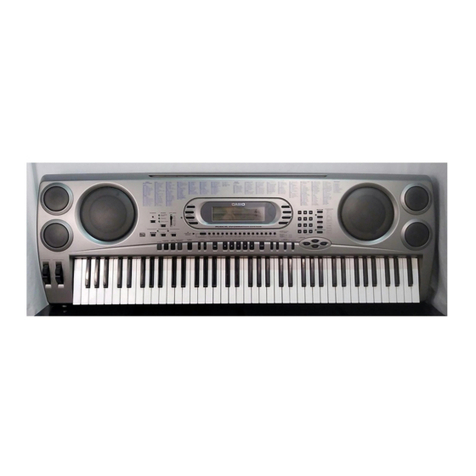
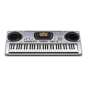
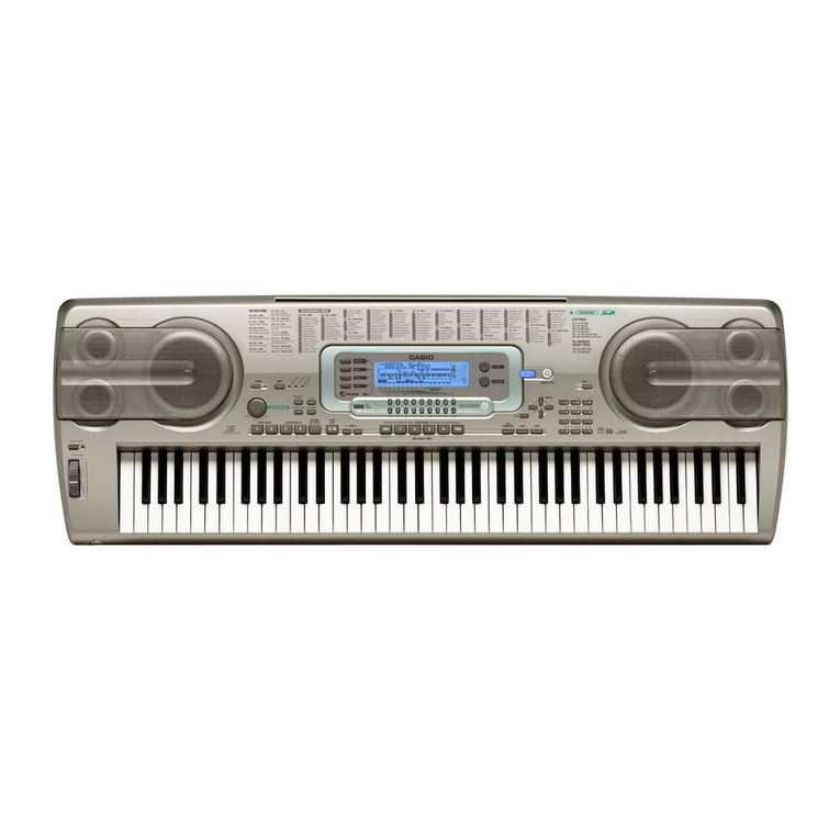
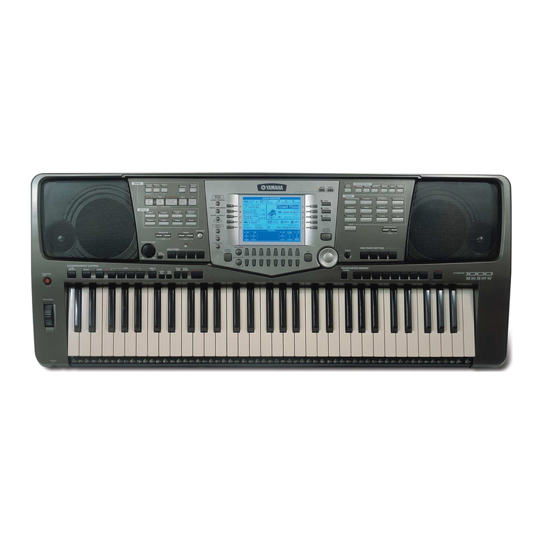
Casio WK-3700 User manual

ELECTRONIC KEYBOARD
WK-3700
MAY. 2005
WK-3700

CONTENTS
Specifications ---------------------------------------------------------------------------------------------- 1
Block Diagram --------------------------------------------------------------------------------------------- 3
Circuit Description --------------------------------------------------------------------------------------- 4
Printed Circuit Board ------------------------------------------------------------------------------------ 6
Disassembly ---------------------------------------------------------------------------------------------- 11
Diagnostic Program------------------------------------------------------------------------------------ 17
Exploded View ------------------------------------------------------------------------------------------- 20
Parts List--------------------------------------------------------------------------------------------------- 21
Schematic Diagrams----------------------------------------------------------------------------------- 25

— 1 —
SPECIFICATIONS
GENERAL
Keyboard: 76 standard-size keys, 6 1/4octaves with touch response (OFF/1/2/3)
Tones: 332 Advanced Tones + 200 Preset Tones + 18 Drum Sets + 100 standard user tones
+ 20 user tones with waves* + 4 user drum sets with waves* + 50 drawbar organ
tones + 100 user drawbar organ tones (824 tones total); layer/split
Polyphony: 32 notes maximum (10 for certain tones)
Drawbar Organ Function
Drawbars: 9 (16’, 5 1/3’, 8’, 4’, 2 2/3’, 2’, 1 3/5’, 1 1/3’, 1’)
Percussion: Second, Third
Click: On, Off
Effects: DSP (200 types: internal, 100 user areas) + Reverb (16 types) + Chorus (16 types) +
Equalizer (10 types, 4 bands)
Auto Accompaniment
Rhythm Patterns: 176 (internal, 16 user areas*)
Tempo: Variable (226 steps, = 30 to 255)
Chords: 3 fingering methods (CASIO CHORD, FINGERED, FULL RANGE CHORD)
Rhythm Controller: START/STOP, INTRO/ENDING 1 and 2, VARIATION/FILL-IN 1 and 2, SYNCHRO/FILL-IN
NEXT
Accomp Volume: 0 to 127 (128 steps)
One-touch Presets: Recalls settings for tone, tempo, layer on/off, and harmonize on/off in accordance with
rhythm.
Auto Harmonize: 10 types : Automatic addition of notes that harmonize with melody note in accordance
with specified Auto Accompaniment chords.
Memory Function
Songs: 5
Recording Tracks: 6 (2 through 6 are melody tracks)
Recording Methods: Real-time, step
Memory Capacity: Approximately 10,000 notes (total for 5 songs)
Edit Function: Equipped
Demo Tunes: 3
Synthesizer Function
Parameters: Attack time; release time; resonance; cutoff frequency; vibrato type; vibrato delay; vibrato
depth; vibrato rate; octave shift; level; touch sense; reverb send; chorus send; DSP line;
DSP type; DSP parameter; ModulationAssign
Registration Memory
Number of Setups: 32 (4 setups ×8 banks)
Memory Contents: Tone, Rhythm, Tempo, Layer on/off, Split on/off, Split point, Harmonize on/off, Mixer settings
(Channels 1 to 10), Effect settings, Touch Response settings, Assignable jack setting,
Transpose, Tuning, Accompaniment volume setting, Pitch bend range, Auto Harmonize
type, MODE button setting, Synchro standby state, Mixer Hold, DSP Hold, Synthesizer
Mode parameters
Mixer Function
Channels: 16
Parameters: Tone; part on/off; volume; pan pot; octave shift; coarse tune; fine tune; reverb send; chorus
send; DSP line; DSP level, DSP pan, DSP system reverb send, DSP system chorus send
MIDI: 16 multi-timbre receive, GM Level 1 standard
Other Functions
Pitch Bend Range: Adjustable (12 semitones upwards and downwards)
Modulation: Equipped
Transpose: 49 steps (–24 semitones to +24 semitones)
Tuning: Variable (A4 = approximately 440Hz ±100 cents)
LCD: Adjustable contrast
Tune Number Name Composer Play Time
0 White Winter Hage Software 2:32
1 Serendipity Waltz TECH-NOTE INTERNATIONAL LTD. 2:01
2 Street Beatz Steve Turner 2:10
— 2 —
SMF Player: Flash memory storage for up to 200 files*
Supported Format: SMF0
Flash Memory
Capacity: 4MB
Shared Area: Approximately 3.5MB (waveform data, accompaniment data, SMF data)
Further storage of waveform, accompaniment, and SMF data becomes impossible after
the total of such data reaches approximately 3.5MB.
Card Slot 3.3V SmartMediaTM (8MB, 16MB, 32MB, 64MB, 128MB)
Functions: Save and load of user tones, user songs, and registration data; playback of SMF; card
formatting; file delete; file rename
Floppy Disk Drive
Type: 3.5" FDD
Formats: 2DD (720KB MS-DOS format)
2HD (1.44MB MS-DOS format)
Functions: Save and load of user tones, user songs, and registration data; playback of SMF; disk
formatting; file delete; file rename
Terminals
MIDI Terminals: IN, OUT
Sustain/Assignable Terminal
: Standard jack (sustain, sostenuto, soft, rhythm start/stop)
Headphones: Stereo standard jack
Output Impedance : 200Ω
Output Voltage : 250mV (RMS) MAX
Line Out (R, L/MONO): Standard jack ×2
Output Impedance : 3kΩ
Output Voltage : 1.5V (RMS) MAX
Power Supply Terminal: 12V DC
Power Supply: Dual power supply system
Batteries: 6 D-size batteries
Battery Life: Approximately 4 hours continuous operation on alkaline batteries
AC Adaptor: AD-12
Auto Power Off: Turns power off approximately six minutes after last key operation. Enabled under battery
power only, can be disabled manually.
Speaker Output: 6.1W + 6.1W
Power consumption: 12V 18W
Dimensions: 122.3 ×42.3 ×16.0 cm (48 3/16 ×14 11/16 ×5 5/16 inch)
Weight: Approximately 10.0 kg (22.0 lbs) (without batteries)
* The same memory area is used to store waveform data, accompaniment data, and SMF data.
ELECTRICAL
Current drain with 12 V DC:
Consumption Current 1430 mA ±20 %
Consumption Current at idle 230 mA ±20 %
with 16 keys from E1 to F3 pressed in 479 Ocarinag
Volume: maximum, Velocity: maximum
Speaker output level (Vrms with 8 Ωload each channel):
with key L(E1)/R(G1) in 479 Ocarinag
Volume: maximun, Velocity: maximum 6000 mV ±20 %
Phone output level (Vrms with 32 Ωload each channel):
with key L(E7)/R(G7) in 479 Ocarinag
Volume: maximun, Velocity: maximum 400 mV ±20 %
Output level (Vrms with 47 KΩload each channel):
with key L(E1)/R(G1) in 479 Ocarinag
Volume: maximun, Velocity: maximum 3200 mV ±20 %

— 3 —
BLOCK DIAGRAM
CONSOLE PCB (M734-CN1M)
CONSOLE PCB
(M734-CN8M)
Keyboard PCB
(JSM764T-KY1M/
KY2M)
SUB PCB
(M734-MA2M)
MAIN PCB
(M737-MD1)
LCD PCB
(M734-LCD1M)
CONSOLE PCB
(M734-CN5M)
CONSOLE PCB
(M734-CN4M)
MIDI
RAM (1Mbit)
IC4
CY62128VLL-70AZI
Assingnable Jack
Reset IC
IC8
R1151N001C-TR RESET
16.384MHz
EA0 ~ EA15, EA18
ED12 ~ ED19
Filter
IC202, IC203
DAC IC5
uPD63200GS
Power Amplifier
IC205
LA4636 Power Supply Circuit
Q201 ~ Q205,
IC201, D205
(9-12V)
VC
(9-12V)
VCP
APO Battery
Speakers
(L)
(R)
Phones/Output
LOUT
CONT
E
R/W
RS
ROUT
(5V)
VF5
(5V)
VD5
FLASH ROM (32MBit)
IC2
LH28F320BFHPBTL70
RAM (2Mbit)
IC6
LP62S2048X-70LLT/Q
ROM (128Mbit)
IC36
MR27V12800J137TN3D
IC17
TC74LCX245FT
FDD Controller
IC21
ML6757GA-115
Keyboard
IN
OUT
LCD Controller
ML9040-B02GA (IC401)
D201
LINE OUT
L R
3.5" FDD UnitSmart media Unit
MA0 ~ MA20
MA0 ~ MA21
MA0 ~ MA16, MA25
MA0 ~ MA13, MA25
CONSOLE PCB
(M734-CN2M)
SUB PCB
(M734-MA3M)
CONSOLE PCB
(M734-CN3M)
MD0 ~ MD15
MD0 ~ MD15
MD0 ~ MD7
MD0 ~ MD7
MD0 ~ MD7
Q207 D209
MPU
IC15
uPD914AGM-3ED
HUMANIZERSYNTH
DRAWBER
Main
Volume
KC0 ~ KC7
FI0, KI0 ~ KI2
KC0 ~ KC3
MD0 ~ MD15
MA0 ~ MA3
DB0 ~ DB7
SWCO ~ SWC6
SWIO ~ SWI7
PWSW
RESB
TXDO
TXDI
BUTTON/LED
CONTROLLER
IC301
UPD65881GK-062-9ET
Buttons
SI0 ~ SI9,
FI0 ~ FI9
DSP ON/OFF
KEY/BUTTON
CONTROLLER
IC20
TC190C020AF-001
AC ADAPTOR
DC 12V

— 4 —
CIRCUIT DESCRIPTION
KEY MATRIX
KC0 KC1 KC2 KC3 KC4 KC5 KC6 KC7
FI0 E11F11F#11G11G#11A11A#11
SI0 E12F12F#12G12G#12A12A#12
FI1 B11C21C#21D21D#21E21F21F#21
SI1 B12C22C#22D22D#22E22F22F#22
FI2 G21G#21A21A#21B21C31C#31D31
SI2 G22G#22A22A#22B22C32C#32D32
FI3 D#31E31F31F#31G31G#31A31A#31
SI3 D#32E32F32F#32G32G#32A32A#32
FI4 B31C41C#41D41D#41E41F41F#41
SI4 B32C42C#42D42D#42E42F42F#42
FI5 G41G#41A41A#41B41C51C#51D51
SI5 G42G#42A42A#42B42C52C#52D52
FI6 D#51E51F51F#51G51G#51A51A#51
SI6 D#52E52F52F#52G52G#52A52A#52
FI7 B51C61C#61D61D#61E61F61F#61
SI7 B52C62C#62D62D#62E62F62F#62
FI8 G61G#61A61A#61B61C71C#71D71
SI8 G62G#62A62A#62B62C72C#72D72
FI9 D#71E71F71F#71G71
SI9 D#72E72F72F#72G72
Note: Each key has two contacts, the first conatct 1and second contact 2.
Key
Second contact First contact FI
KC
SI
21
NOMENCLATURE OF KEYS
C2
C#2 D#2 F#2 G#2 A#2 C#3 D#3 F#3 G#3 A#3 C#4 D#4 F#4 G#4 A#4 C#5 D#5 F#5 G#5 A#5 C#6 D#6 F#6 G#6 A#6
D2 E2 F2 G2 A2 B2C1 D1 E1 F1 G1 A1 B1 C3 D3 E3 F3 G3 A3 B3
C#1 D#1 F#1 G#1 A#1
C4 D4 E4 F4 G4 A4 B4 C5 D5 E5 F5 G5 A5 B5 D6 E6 F6 G6 A6 B6C6 C7
E1

—5 —
BUTTON MATRIX
KEY LED MATRIX
KI2
AUTO HARMONIZE
0
1
7
FI10
+
3
6
DEMO
KI0
LAYER
2
5
9
KI1
SPLIT
–
4
8
KC4
KC5
KC6
KC7
SWI4
INTRO/
ENDING 2
1
CH10
CH5
CH6
ARPEGGIATOR
DSP
ON/OFF
SWI5
VARIATION/
FILL-IN 1
2
CH11
CH14
CH7
EXIT
씰
SWI2
MODE
START/
STOP
TEMPO
UP
CH3
TONE
EDIT
1 FEET
DOWN
PIANO
SETTING
SWI3
INTRO/
ENDING 1
BANK
CH9
CH4
EFFECT
EDIT
STORE
DRAWBER
SWI0
ACCOMP
VOLUME
SEQ
STRAGE
CH1
SETTING
SYNTH
TONE
SWI1
ONE
TOUCH
PRESET
TEMPO
DOWN
SMF
PLAY
CH2
PART
EDIT
HUMANIZER
RHYTHM
SWI6
VARIATION/
FILL-IN 2
3
CH12
CH15
CH8
씱
쑼
SWI7
SYNCRO/
FILL-IN
NEXT
4
CH13
CH16
1 FEET UP
쑿
SWC0
SWC1
SWC2
SWC3
SWC4
SWC5
SWC6

— 6 —
PRINTED CIRCUIT BOARD
MAIN PCB M737-MD1
Top View
Bottom View

— 7 —
SUB PCB M734-MA2M
Top View
Top View
SUB PCB M734-MA3M

— 8 —
DISPLAY PCB M734-LCD1M
Top View

— 9 —
CONSOLE PCB M734-CN1M
CONSOLE PCB M734-CN4M
CONSOLE PCB M734-CN3M
CONSOLE PCB M734-CN2M CONSOLE PCB M734-CN5M
CONSOLE PCB M734-CN6M
CONSOLE PCB M734-CN7M

— 10 —
KEYBORD PCB JCM764T-KY1M
KEYBORD PCB JCM764T-KY2M

— 11 —
DISASSEMBLY
1. Remove the battery cover and then the battery.
2. Remove 36 screws and then the upper case.
3.
Remove 4 screws, 8 speaker cords, 2 battery cords, 1cord (PM), 5 connectors (JD, JG2, JH, JK, JJ) and then the PCB ASS'Y (MA2M).
Speaker cords (O)
Speaker cords (W)
Battery cord (R)
Battery cord (B)
Screw
Connectors
Screw
Screw
Speaker
cords (O)
Speaker
cords (W)
Screw
Connectors
Screws
ConnectorCord

— 12 —
4. Remove 5 screws, 5 connectors (JA, JB, JD, JE, JF) and then the PCB ASS'Y (MA1M).
Screws
ConnectorsConnectors
5. Remove 8 screws, 1 connector and then the LCD ASS'Y (LCD1M).
Note: Tighten the screws in the order from 1 to 8 when
reassembling.
Screws
Screws
Connector
367
1852
4

— 13 —
Connector
CN1M
6. Remove the volume knob, screws, connectors and then the CN1, CN2, CN3, CN4, CN5, CN6, CN7.
Screws
Volume knob
CN2M
CN5MCN4M
CN3M
CN6M CN7M
CN1MCN2M CN6M CN5M CN6M
CN3M
CN7M

— 14 —
8. Remove 29 screws and then the lower case.
7. Remove 2 screws and then the Bender assy.
Screws
Note: Tighten the screw with the arrow mark in the figure first when reassembling.

— 15 —
10.Remove the rubber keys.
Projection
Note: Pay attention to the positions of the rubber keys as one of them has a different length.
Match the projections of the rubber keys with the holes of the lower case when reassembling.
9. Remove 24 screws and then the PCB ASSY (KY1M, KY2M).

— 16 —
11.Remove 27 screws and then the white keys.
12.Remove the black keys.
Note: Pay attention to the positions of the screw holes when
reassembling.

— 17 —
DIAGNOSTIC PROGRAM
■ Initial Setup
1. Connect an AC adaptor.
2. Connect a Sustain pedal.
3. "Main" volume: MAX.
NOTE: If there is no pedal or MIDI cable, pedal or MIDI check can be skipped.
■ How to start diagnostic program
1. Press the “POWER” button while pressing the “Cursor key Up” and “Cursor key Down” buttons.
2. Release the “POWER” button first while still pressing the “Cursor key UP” and “Cursor key Down” buttons.
3. Release the “Cursor key UP” and “Cursor key Down” buttons. “TEST 737” appears on the LCD.
NOTE:
Refer to the figure below for the LCD messages that appear during the diagnostic program.
■Diagnostic program
1. Button check
1Press “DSP” button.
2Press buttons in the following order.
NOTE: NG sound sounds when a button is defective or buttons are pressed in a wrong order.
LCD message appears in the area 1.
Gran ndP o
514
8 7
2
E
3
BCD A 60 9
1
3
24 5
6 7
8 9 0 A B C D E F G H I J K
L
O
PQRSTUVW Y
Z[\]^abcd
f
g
h i
jkm
n
o p q r
s
u
t
y
x
v
w
z
{
}
~
|
l
e
N
M
YCH 9
ZCH 10
[CH 11
\CH 12
]CH 13
_CH 14
aCH 15
bCH 16
cDSP CH
d
DRAWBAR ORGAN
eTONE
fRHYTHM
gDSP
hPIANO SETTING
iCursor key Up
jCursor key Right
kCursor key Down
1MODULATION
2MODE
3
ONE TOUCH PRESET
4DISK/CARD
5ACCOMP VOLUME
6SONG MEMORY
7INTRO/ENDING 1
8INTRO/ENDING 2
9
VARIATION/FILL-IN 1
@
VARIATION/FILL-IN 2
A
SYNCHRO/FILL-IN NEXT
BSTART/STOP
CTEMPO쑼
DTEMPO쑿
EBANK
FREGISTRATION 1
GREGISTRATION 2
HREGISTRATION 3
IREGISTRATION 4
JSTORE
K
TRANSPOSE/FUNCTION
LMIXER
MSYNTH
NEFFECT
OSMF PLAYER
PCH 1
QCH 2
RCH 3
SCH 4
TCH 5
UCH 6
VCH 7
WCH 8
UP
lCursor key Left
mEXIT
n
AUTO HARMONIZE
oSPLIT
pLAYER
q0 buttons
r1 buttons
s4 buttons
t7 buttons
u8 buttons
v5 buttons
w2 buttons
x- buttons
y+ buttons
z3 buttons
{6 buttons
|9 buttons
}DEMO
MODE
OTP
CARD
ACMP VOL
SONG
INT/END1
INT/END2
VAR/FIL 1
VAR/FIL 2
SYNCHRO
STRT/STP
TEMPO/DW
TEMPO/UP
BANK
REGIST 1
REGIST 2
REGIST 3
REGIST 4
STORE
TRAN/FUNC
MIXER
SYNTH
EFFECT
SMF
CH 1
CH 2
CH 3
CH 4
CH 5
CH 6
CH 7
CH 8
1Ft UP
CH 9
CH 10
CH 11
CH 12
CH 13
CH 14
CH 15
CH 16
DSP CH
DRAWBAR
TONE
RHYTHM
DSP
PIANO
UP
RIGHT
DOWN
LEFT
EXIT
HARMO
SPLIT
LAYER
0
1
4
7
8
5
2
-
+
3
6
9
DEMO
SW OK
Message on LCD Message on LCD Message on LCD Message on LCD

—18 —
Message on LCD
1ACJ ON
1SUS CHK
1SUS ON
1SUS OFF
1VOLT HI
1TG MAX L
1TG MAX C
1TG MAX R
1ROM CHK
앗
1ROM OK
1FMC CHK
앗
1FMC OK
1MIDI OK
1DRAM OK
1CRAM OK
2. AC adaptor detection check.
1Press “TONE”button.
2When the instrument detects that an AC adaptor is plugged in, an OK sound
sounds. “ACJ OFF”appears and an NG sound sounds when the AC adaptor
is not plugged (when batteries are used).
3. Sustain jack check. (If no pedal, this check can be skipped)
1Press “RHYTHM”button.
2Press “Sustain pedal”.
3Release “Sustain pedal”.
4NG sound, “OFF”sound this case, must be audible.
4. Low Voltage detection check.
1Press “DRAWBAR ORGAN”button.
2OK sound must be audible.
5. MIDI IN/OUT check (If there is no MIDI cable, this check can be skipped)
1Connect MIDI IN and MIDI OUT terminals with a MIDI cable.
2Press “3”button.
3Disconnect the MIDI cable.
6. Sound Source check
1Press “7”button.
2The MAX sin sound sounds from Left spesker.
3Press “8”button.
4The MAX sin sound sounds from Both spesker.
5Press “9”button.
6The MAX sin sound sounds from Right spesker.
7. ROM check
1Press “INTRO/ENDING1”button.
8. Flash memory check
1Press “INTRO/ENDING2”button.
9. Flash memory SUM check
1Press “SONG MEMORY”button.
10. DSP RAM check
1Press “VARIATION/FILL-IN 2”button
11. CPU RAM check
1Press “SYNCHRO/FILL-IN NEXT”button.
1FMS CHK
앗
1FMS 3C6A
Table of contents
Other Casio Electronic Keyboard manuals

Casio
Casio SA-65 User manual

Casio
Casio MA-150 User manual

Casio
Casio CTK-1500 User manual

Casio
Casio CTK-4200 User manual

Casio
Casio HT-3000 User manual

Casio
Casio SK-60 User manual

Casio
Casio Celviano AP420ES1B User manual

Casio
Casio Celviano AP-400 User manual

Casio
Casio Tone Bank CT-636 User manual

Casio
Casio Privia PX-320 User manual

Casio
Casio CTK-480 User manual

Casio
Casio CTK-671 User manual

Casio
Casio CTK-691 User manual

Casio
Casio CPS-130 User manual

Casio
Casio WK-200 User manual

Casio
Casio CTK-431 User manual

Casio
Casio LK-50 Instruction manual

Casio
Casio Casiotone CTI-510 User manual

Casio
Casio LK-50 Operating instructions

Casio
Casio Tone Bank CT-650 User manual