CaterWil GTS3 User manual

1
Wheelchair-transformer CaterWil
model: GTS3
Instructions for Use
Caterwil LLC, phone +7-(383)-319-7837, www.caterwil.com
ver 1.0.1 rev 25.01.2017

2
Table of contents
1. Product Description...........................................................................................................................................3
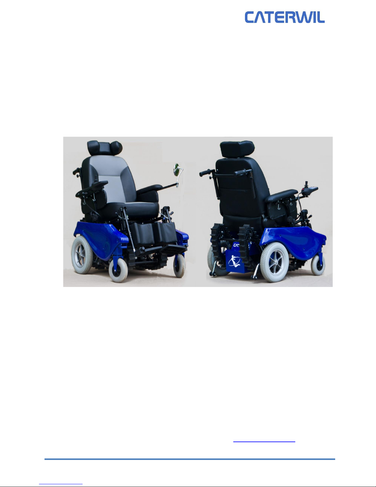
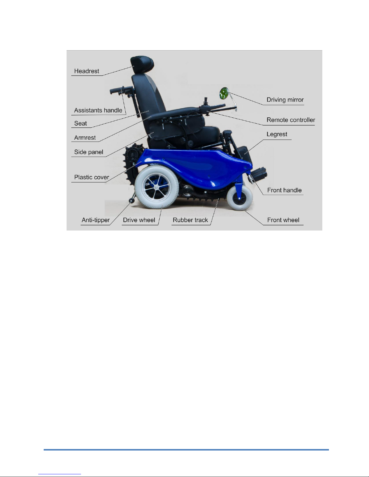
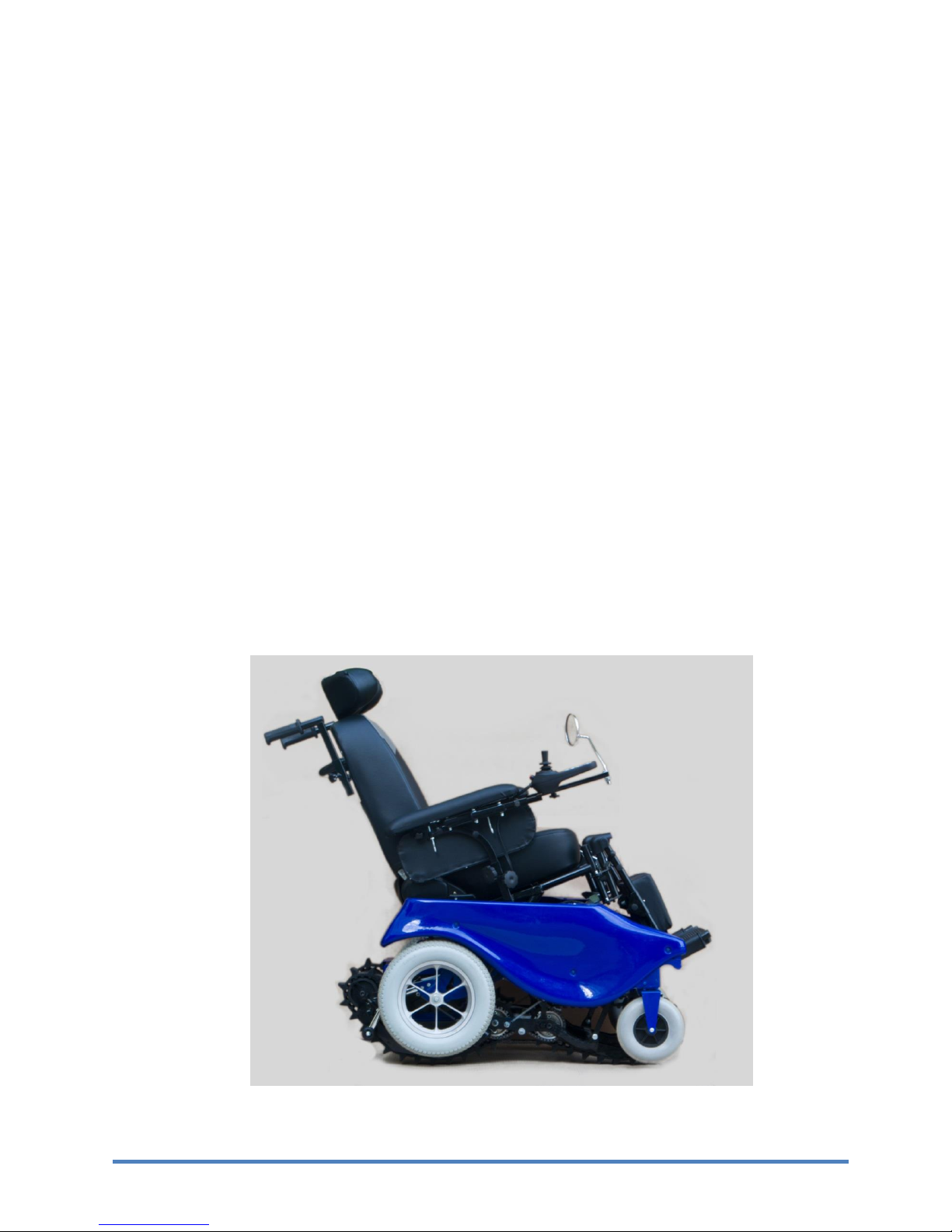
1.1 General description ...................................................................................................................................3
1.2 Technical specifications.............................................................................................................................4
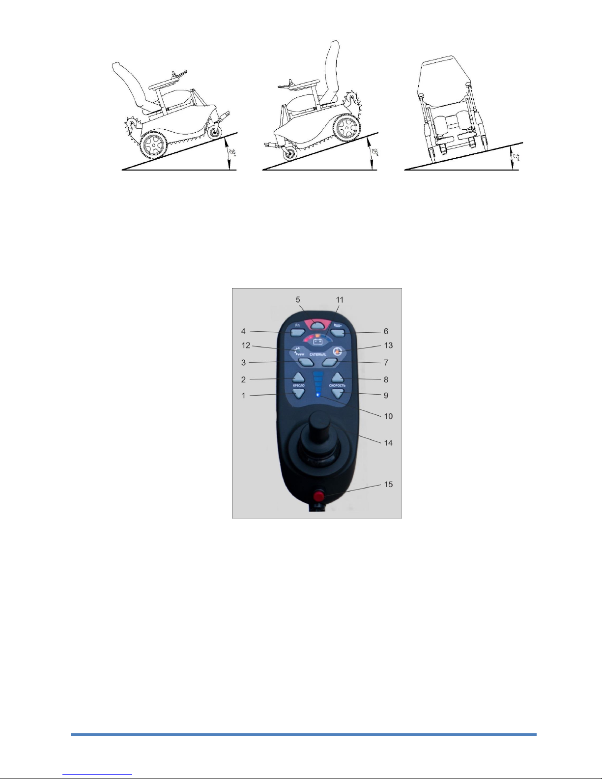
1.3 Remote controller .....................................................................................................................................5
1.4 Batteries specifications .............................................................................................................................7
1.5 Safety features...........................................................................................................................................7
1.6
Electromagnetic
I
n
terfer
ence
(EMI).....................................................................................................8
1.7 Electrostatic discharge (ESD) protection ..................................................................................................8
1.8
Materials safety
......................................................................................................................................8
1.9
Vibrations protection
.............................................................................................................................8
2. Start-up and restarting instructions .................................................................................................................8
2.1
Installing footrests
..................................................................................................................................8
2.2
Adjusting the Lower Leg Length (see fig. 5)..............................................................................................9
2.3
Adjusting footrest angle (see fig. 5)..........................................................................................................9
2.4
Adapting the Remote controller position to Arm Length ........................................................................9
2.5
Swing-away Remote controller holder...................................................................................................10
2.6
Adjusting the armrest..............................................................................................................................10
2.7
Lap Belt ....................................................................................................................................................10
2.8
Turning on/off and operating .................................................................................................................11
3. Maintenance Manual ......................................................................................................................................11
3.1 Cleaning and Care....................................................................................................................................11
3.2 Changing the Fuse ...................................................................................................................................11
3.3 Replacing
Batteries
...............................................................................................................................12
3.4 Tighten screws.........................................................................................................................................13
3.5 Troubleshooting ......................................................................................................................................13

3
1. Product Description
1.1 General description
Fig. 1
Wheelchair transformer CaterWil GTS3 with electrical drive is designed to be driven by disabled
person or by the attendant. The wheelchair can overcome different kind of obstacles including stairs.
CaterWil has wheels and tracks platform. Wheels platform is used for moving on a smooth
surface. Track platform is needed for overcoming stairs, curbs and other obstacles. In a wheel mode
the track platform is hidden in its upper position doesn’t slug and doesn’t create resistance for moving.
When the button pressed on a remote control the linear actuator is activated and though the
mechanical system of levers the track platform goes down. Caterpillars are moved by the motors that
rotate the wheels but using the additional gear that provides higher torque and lower speed on stairs.
The passenger’s seat is installed on hinges and turned by the separate drive. Turning the seat
is important when going up and down the stairs for displacing the center of mass and saving a vertical
position of the passenger that is safe and comfortable. The seat is controlled by electronics in
automatic cycle. Three axis sensors accelerometers determines the position of the main platform and
the seat, using the acquired data system smoothly turns the seat leaving it’s constant position relative
to the horizon.
The power supply of the system is provided by batteries. Two main drives (left and right) that
rotate wheels or tracks (depends on moving mode) are made as DC gear-motors. Each of three linear
actuators is made as a DC motor driving a rod via a gear system. The actuators strokes are limited by
limit switches.

4
The electronic system consists of two modules: remote control and process execution block.
The data transition between the modules is organized by wire connection.
For safety management the main drive’s system is equipped by electromagnetic brakes that
activates in case of power loss. Also main drives has special handles that can disjoin the gears from
wheels and tracks, this makes possible to roll the wheelchair by hands if the battery is discharged. The
battery charge is designed for overcoming 15 km distance on smooth surface. Electronics monitors the
battery charge and informs the user in case of low level.
The CaterWil dimensions don’t exceed sizes of usual wheelchair. The width of the device is 65
cm that allows using it at home conditions, going through interior doors and using elevators.
The CaterWil can climb stairs up to 40 deg on tracks and can climb ramps up to 18 deg on wheels
(fig. 2)
1.2 Technical specifications
Table 1. Wheelchair specifications.
№
Characteristic
Unit
Value
Notes
1
Dimensions
(length x width x height)
mm
(1200-1400)x645x1230
Adjustable length
2
Seat width
mm
460
3
Seat depth
mm
435
4
Seat height
mm
530
5
Armrest height
mm
150-220
Adjustable
6
Lower leg length
mm
400-550
Adjustable
7
Weight empty
kg
105
8
Max. load capacity
kg
120
9
Front wheel size
mm
200
10
Drive wheel size
mm
330
11
Max speed on wheels
km/h
7
12
Max speed on tracks
km/h
0,7
13
Distance range
km
20
14
Max stairs angle
deg
40
At step height 160 mm, step
rounding radius 10 mm
15
Max step height
mm
200
At stair angle 25 deg, step
rounding radius 10 mm
16
Max step rounding radius
mm
20
At step height 160 mm, stair
angle 35 deg
17
Noise level
dBA
≤65
18
Operating temperature
Deg C
-10 to 40
19
Battery capacity
A*h
33
2 pcs AGM batteries
20
Drive motors voltage
V
24
2 pcs DC motors
21
Charger power requirements
V
220
22
Nominal charging current
A
5
23
Wheelchair protective system
IP54

5
fig.2
1.3 Remote controller
The Remote controller is used to control the power wheelchair. The Remote controller consists
of a keypad, LED display and joystick. The control panel is used to switch the power wheelchair on and
off, to enter driving commands and to display the current state of certain functions and components.
fig. 3
1. Chair down button
2. Chair up button
3. Track mode button
4. Special functions button
5. On/Off button
6. Horn button
7. Wheel mode button
8. Max speed down button
9. Max speed up button
10. Max speed level LED indicator
11. Battery charge LED indicator
12. Track mode LED indicator
13. Wheel mode LED indicator
14. Joystick
15. ESD button

6
Chair up and down buttons
Moves chair up or down in wheel mode for adjusting chair angle
Wheel and track mode buttons
Start transforming into wheel mode (fig. 1) or track mode (fig. 4)
Special functions button
Provide additional functions in combination with other buttons
On/Off button
The on/off key is used for switching the power wheelchair on and for switching the power wheelchair
off.
Horn button
The horn will sound as long as the horn key is being pressed.
Speed up and down buttons
Pressing the speed buttons shortly increases or reduces the speed level. After reaching the maximum
or minimum speed level nothing changes.
Joystick
The joystick controls the direction and speed of travel.
Battery Capacity LED indicator
The LEDs show the battery charge
Speed Level LED indicator
The LEDs show the currently selected speed level.
Track and wheel mode indicators
Shows current mode activated. In activating process if blinking
Fig. 4

7
1.4 Batteries specifications
The wheelchar CaterWil GTS3 has 2 AGM batteries that are maintenance-free.
Table 2. Delta HRL 12-33 battery specifications
Nominal voltage
12V
Rated capacity (2 hour rate)
33Ah
Number of cell
6
Weight
11.5 kg
Dimensions (height x length x width)
195x130x168 mm
Discharge temperature
-20 to 60°C
Charge temperature
-10 to 60°C
Storage temperature
-20 to 60°C
Self discharge per month
3% of capacity at 20℃
Number of cycles at 40% capacity loss.
300 cycles of 100% discharge
1.5 Safety features
The wheelchar has safety features to provide maximum safety during exploitation,
transportation and storage.
Table 3. Safety features.
№
Safety feature
Notes
1
ESD button
For emergency stop
2
Electromagnetic brakes that are
active when power failure or
shutdown
Parking-brakes and emergency brakes
3
40A fuse
For overload or short circuit prevention
4
Battery charge indicator
For battery discharge prevention
5
Emergency stop when Remote
controller communication is failed
Automatic stop when Remote controller is unplugged
or wires are damaged
6
Motors load control
If motors are overloaded systems stops automatically
7
Brakes monitoring
Automatic stop when brakes are unplugged or wires
are damaged
8
Roll and pitch control system
System controls roll and pitch angles of the
wheelchair and passengers seat. It slows down or
stops moving if angles are dangerous.
9
Stop ends on linear actuators
Used for limiting motion of actuators
10
System self diagnostic
System checks all the components. If they are
plugged and works fine. If not it will show an error
(See Table 5. Troubles and remedies)
11
Safety belt
Optional
The driver is protected from scalding. The potential sources of heat like power electronics,
motors and batteries are isolated from user.

8
1.6
Electromagnetic
I
n
terfer
ence
(EMI)
El
ectrom
agnetic
interference
(EMI) is interference that can be generated
from sources such as radio
and
TV
stations, amateur
rad
i
o
(HAM)
transmitters, two-way radios, and cellular phones.
Caterwil electronics is designed stable to EMI, all control signals are grounded and filtered by
hardware and software. Caterwil has been tested to a radiated
immunity
level of 20 volts per
m
e
ter.
This means that the wheelchair is stable under
el
ectrom
agnetic
interference of household equipment,
personal devices, radio transmitters, TV stations and other public equipment.
1.7 Electrostatic discharge (ESD) protection
The frame of the CaterWil wheelchair is grounded, that provides normal level of ESD
protection. There is no need to use personal ESD protective equipment.
1.8
Materials safety
The chair and accessories are made of non-harmful non-allergic materials that has no
limitations for contact with human skin
1.9
Vibrations protection
The wheelchair can generate low frequency vibrations from 0.1 to 80 Hz from drive chains and
tracks. CaterWil is equipped with series of plastic and rubber dampers that reduce vibrations
amplitude and protect user from uncomfortable feelings and motion sickness.
2. Start-up and restarting instructions
2.1
Installing footrests
Dismantling
1. Remove the calf band.
2. Flip the footplate up, release the footrest lock (see fig. 4) and swing the footrest either to the
inside or out-side.
3. Pull the footrest up to remove it.
Reassembly
1. Reinsert the footrest from above by placing it in the holding device and swinging it forward
until the footrest lock engages.
2. Reattach the calf band to the holding device.

9
2.2
Adjusting the Lower Leg Length (see fig. 5)
1. Loosen the screws on the footrest bar.
2. Move the footplate up or down to adapt the height to the individual lower leg length and seat
cushion thickness.
3. Retighten the screws.
2.3
Adjusting footrest angle (see fig. 5)
To elevate the footrest:
1. Use the release lever on the footrest
2. Move the footrest to the desired position
3. Let go of the release lever
Fig. 5
2.4
Adapting the Remote controller position to Arm Length
To adapt the Remote controller to the arm length of the user, you must loosen a clamper on the
Remote controller holder (see fig. 6). You can now slide the control panel backwards and forwards.
Fig. 6

10
2.5
Swing-away Remote controller holder
To allow the user to drive the power wheelchair closer to an object or under the edge of a table, the
control panel can be swung to the side (see fig. 7).
1. Swing the Remote controller holder to the side.
2. Push it to bring the Remote controller holder back to its original position.
Fig. 7
2.6
Adjusting the armrest
To adapt the armrest height to the arm length of the user, you must loosen two clampers on the
armrest holder (see fig. 6). You can now slide the armrest up and down.
2.7
Lap Belt
The GTS3 can be equipped with a lap belt.
To apply the lap belt, insert the two buckle halves into each other until they lock in place fig. 8).
Then, verify that the belt has locked by trying to pulling it apart. The lap belt should not be too tight on
the body. Objects caught under the belt can cause painful pressure sores.
To open the lap belt, press the red release button.
The belt length can be adjusted on both sides.
Fig. 8

11
2.8
Turning on/off and operating
1. Make sure the ESD button is pressed. If it is not - push it to activate the wheelchair.
2. Press the On/Off button to turn on the wheelchair
WARNING Make sure that all other buttons are not pressed and the joystick is not
inclined before turning on the wheelchair. Otherwise the wheelchair turns off
automatically.
3. After 1 second of loading the wheelchair can be operated. The wheelchair is in safe mode
until any button or joystick activated. To start driving incline the joystick in direction of
driving. To stop driving release the joystick. To start execution of other commands press
necessary button.
4. Press the On/Off button one more time to turn the wheelchair off when finished.
NOTICE There is no need to press ESD button to turn off the wheelchair during normal
operations. Press the ESD button for emergency stop only.
3. Maintenance Manual
3.1 Cleaning and Care
WARNING Do not use any aggressive cleansing agents, solvents, or hard brushes for
cleaning the power wheelchair. Never use a water jet or high-pressure cleaning apparatus
for cleaning the power wheelchair.
Prior to disinfection, clean the seat and back upholstery as well as the seat cushion, the control
panel and the armrest.
3.2 Changing the Fuse
The 40 A fuse is located in a fuse holder in the front section of the battery case (see fig. 9).
Open the cap of the safety holder and exchange the fuse. Make sure that the fuse is pressed into
the center of the spring contacts and that it is not at an angle. Close the cap until you feel it snap back
into place.
12 3
Fig. 9

12
1. Fuse cap
2. Fuse, inserted
3. Fuse holder
3.3 Replacing
Batteries
NOTICE
It’s
recommended that both batteries be replaced
if
one battery is defective.
1. Open battery box covering by unscrewing 2 bolts using 8 mm wrench.
2. Unscrew wires from installed batteries
3. Remove batteries from the battery box.
4.
Install
new batteries into the battery box.
5. Screw wires on new batteries as on the fig. 10. Red wire to the red terminal, black wire
to the black terminal.
6. Close the battery box covering back by screwing 2 bolts using 8 mm wrench.
WARNING If wires are connected to the wrong terminals with wrong polarity it will
permanently damage the control system
Fig. 10

13
3.4 Tighten screws
All screws must be tightened with torque according to the table:
Table 4. Screws tightening torque
3.5 Troubleshooting
During the operation there can appear some failures. Please use the table to identify and fix the
problem. If problems can not be solved please inform service center.
Table 5. Troubles and remedies
Trouble
Cause
Remedy
No reaction when try to
turn on the wheelchair
Bad wires connection
Check the wires connections
No contact with a battery
Connect the batteries
Remote controller is failed
Inform service center
LED indicators are on but
Remote controller do not
reply
Remote controller or control
system is failed
Inform service center
1 red LED indicator is
blinking
Low battery charge
Charge the battery
2 LED indicators are blinking
One of the motors is overloaded
Restart the wheelchair, avoid
overloading
Short circuit in one of the motors or
control system is failed
Inform service center
3 LED indicators are blinking
Row or pitch angle excess
maximum
Move the wheelchair to normal
level
4 LED indicators are blinking
Joystick failure
Check the wires connections of
joystick
Inform service center
5 LED indicators are blinking
Brakes failure
Check the wires connections of
brakes
Inform service center
Sudden wheelchair shut
down
Loss of wires connection
Check the wires connections
ESD system was activated
Restart the wheelchair
Control system is failed
Inform service center
Other manuals for GTS3
1
Table of contents
Other CaterWil Wheelchair manuals