Cattron Remtron Pump Boss II Series User manual

Remtron Pump Boss II
User Manual
9M02-8814-A001-EN

Remtron Pump Boss II
User Manual
2
9M02-8814-A001-EN
Version 2.3
WARNING
Read all safety rules and warnings before installing and operating this system.
Revision History
VERSION
DATE
NOTES
1.0
Initial Release
2.0
04/2014
Updated Styles
Revised Content
2.1
08/2014
Corrected Revision Number
Updated Support Facilities
2.2
07/2015
Updated Support Facilities
Removed Old Service Numbers from Images
2.3
08/2019
Document rebranded and contact information updated
!
Any information furnished by Cattron™ and its agents is believed to be accurate and reliable. All specifications are subject to change without notice.
Responsibilityfortheuseandapplication
ofCattronproductsrestswiththeendusersinceCattronanditsagentscannotbeawareofallpotentialuses.
Cattron makes no warranties as to non-infringement nor as to the fitness, merchantability, or sustainability of any Cattron products for any
specificor generaluses.CattronHoldings,Inc.,oranyofitsaffiliatesoragentsshallnotbeliableforincidental
or consequentialdamagesof any
kind. All Cattron products are sold pursuant to the Terms and Conditions of Sale, a copy of which will be furnished upon request. When used as a
tradename
herein, Cattron means Cattron Holdings, Inc. or one or more subsidiaries of Cattron Holdings, Inc. Cattron™, corresponding logos,
and other marks are trademarks or registered trademarksofCattronHoldings,Inc.Othermarksmaybethepropertyofthirdparties.Nothingherein
providesalicenseunderanyCattronoranythirdpartyintellectualpropertyright.

Remtron Pump Boss II
User Manual
3
9M02-8814-A001-EN
Version 2.3
Contents
1. FCC Compliance Statement ................................................................................................................................4
2. Safety Rules.........................................................................................................................................................5
2.1 Installation ..................................................................................................................................................5
2.2 Personal Safety ..........................................................................................................................................5
3. System Description..............................................................................................................................................6
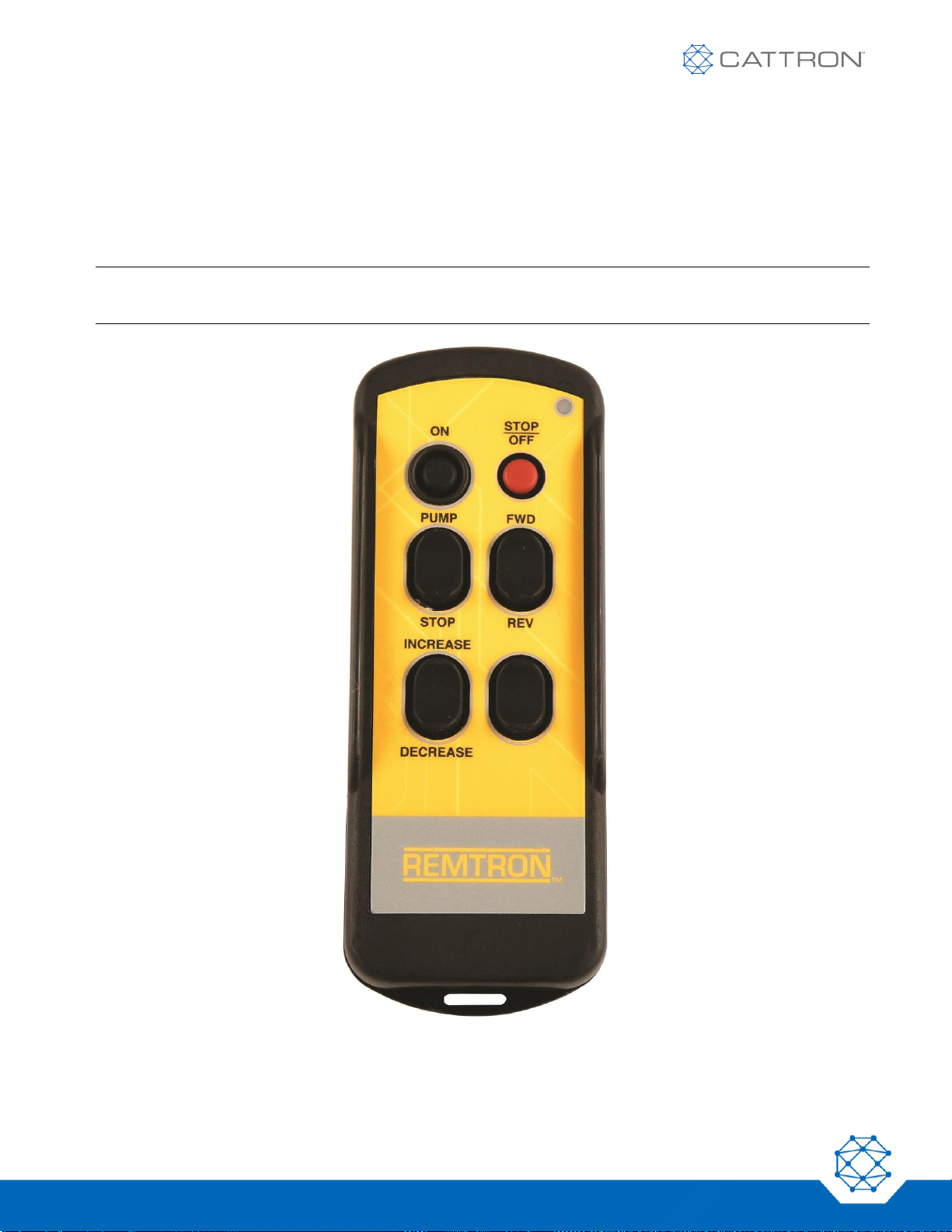
3.1 PBIIT Transmitter .......................................................................................................................................6
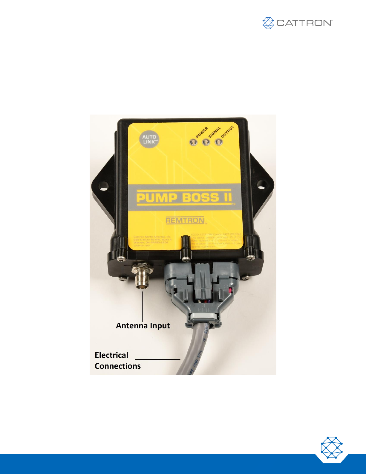
3.2 PBIIR Receiver...........................................................................................................................................8
4. Installation......................................................................................................................................................... 10
4.1 Mechanical .............................................................................................................................................. 10
4.2 Antenna Installation................................................................................................................................. 10
4.3 Locating the Antenna............................................................................................................................... 10
4.4 RCA7 Long Range Antenna.................................................................................................................... 11
4.4.1 Installation Procedure.......................................................................................................................... 11
4.5 Optional Antenna Mount.......................................................................................................................... 12
4.5.1 Installation Procedure.......................................................................................................................... 13
5. Wiring Instructions............................................................................................................................................. 14
6. Configuration Sheets......................................................................................................................................... 15
6.1 197020-10 (PBIIT) Transmitter –197020-20 (PBIIR) Receiver.............................................................. 15
6.2 983090-10 (PBIIT) Transmitter –983090-20 (PBIIR) Receiver.............................................................. 16
6.3 983091-10 (PBIIT) Transmitter –983091-20 (PBIIR) Receiver.............................................................. 17
6.4 983092-10 (PBIIT) Transmitter –983092-20 (PBIIR) Receiver.............................................................. 18
7. Using Your System ........................................................................................................................................... 19
7.1 Starting the System................................................................................................................................. 19
7.2 Pump Operation ...................................................................................................................................... 19
7.3 Helpful Hints ............................................................................................................................................ 20
7.4 System Troubleshooting.......................................................................................................................... 20
7.4.1 System Does Not Operate................................................................................................................... 20
7.4.2 Insufficient Range................................................................................................................................ 20
7.5 Transmitter Troubleshooting ................................................................................................................... 21
8. Replacing the Batteries..................................................................................................................................... 22
9. Replacing the Transmitter................................................................................................................................. 23
9.1 AUTO LINK Procedure............................................................................................................................ 23
10. Replacement Parts............................................................................................................................................ 25
11. Warranty Statement .......................................................................................................................................... 26
12. CE Declaration of Conformity............................................................................................................................ 27

Remtron Pump Boss II
User Manual
4
9M02-8814-A001-EN
Version 2.3
1. FCC Compliance Statement
Pump Boss II® series receivers have been tested and found to comply with the limits for a Class B digital device,
pursuant to Part 15 of the FCC Rules. These limits are designed to provide reasonable protection against harmful
interference in a residential installation.
This equipment generates, uses and can radiate radio-frequency energy, and if not installed and used in
accordance with the user manual, it may cause harmful interference to radio communications. However, there is
no guarantee that harmful interference will not occur in a particular installation.
If this equipment does cause harmful interference to radio or television reception, which can be determined by
switching this equipment on and off, the user is encouraged to try to correct the interference by one or more of the
following measures:
•Reorient or relocate the receiving antenna connected to the device receiving the interference
•Increase the separation between our equipment and the equipment receiving the interference
•Consult Cattron or the distributor where you purchased the system for additional help

Remtron Pump Boss II
User Manual
5
9M02-8814-A001-EN
Version 2.3
2. Safety Rules
WARNING
READ ALL INSTRUCTIONS. Failure to follow these rules can result in serious personal injury.
2.1 Installation
▪PROVIDE A SAFETY CUTOFF SWITCH. If maintenance is required, disconnect the radio from power to
prevent accidental pump activation.
▪USE PROPER WIRING. Loose or frayed wires can cause accidental pump activation.
▪DO NOT INSTALL IN HOT AREAS. This apparatus can be damaged by heat in excess of 160°F (71°C).
▪DO NOT INSTALL IN HIGH VIBRATION AREAS. The life of this apparatus might be shortened through
long exposure to intense shaking or vibration.
2.2 Personal Safety
▪MAKE SURE MACHINERY IS CLEAR BEFORE OPERATING. Do not activate the remote system unless it
is safe to do so.
▪TURN OFF THE RECEIVER POWER BEFORE WORKING ON MACHINERY. To prevent accidental
machine operation, always disconnect the remote system power before doing any maintenance.
!

Remtron Pump Boss II
User Manual
6
9M02-8814-A001-EN
Version 2.3
3. System Description
The Pump Boss II® system consists of a handheld transmitter, a pump-mounted receiver and an antenna.
When the operator presses a switch on the transmitter, a digital message is sent via radio waves to the receiver.
The digital message contains one of millions of possible ID Codes. This unique code makes it possible for the
receiver to respond only to the proper transmitter. Additional codes are also sent, making the chance of false
commands less than 1 in 16 million.
The Pump Boss II® system incorporates a fail-safe ‘STOP’ feature, in that a loss of radio signal drops all relays
within five seconds, thus shutting down the pump. When radio communications are restored, the link to the
receiver is also restored and the user can command any function. During the signal loss, the receiver defaults to
all functions being turned off and the user must restore any latching functions that were reset by the signal loss.
All Pump Boss II® systems incorporate the innovative ‘AUTO LINK™’ function that allows the receiver to ‘learn’
the frequency channel and address of a replacement or spare transmitter. This function allows the Pump Operator
to quickly substitute a spare PBIIT transmitter in the field without the need to physically reconfigure its frequency
channel and address to match that of the receiver.
Receiver relays are Poly fused at 4.5 A. If too much current is drawn through these relays, the Poly fuse will open
and remain open as long as electricity is applied through the relay. Once electricity is removed, the fuse will heal
itself and be ready to operate within about one minute.
Note: In units operated above 24 VDC, the relays are protected with a 7 A fuse. Such fuses can only be
replaced by Cattron.
The Pump Boss II® system complies with the requirements for operation under Part 15 of the FCC rules and
regulations. This means that neither the operator nor the company need apply or register for a license to operate
this equipment.
Note: Any metallic objects will affect radio waves. As the result, the user may encounter difficulty operating in
certain locations. Read the section on using your system so that you can get the best performance.
3.1 PBIIT Transmitter
The Pump Boss II® transmitter is housed in a molded polymer plastic case that is IP67 compliant, which stands
up to extremely rugged use. A key feature is the patented Cattron switch assembly for control inputs. This long-
life elastomeric keypad is ergonomically designed to provide easy operation over long periods of time with
exceptional reliability. A leather holster provides added protection and convenience. An optional clear protective
pouch is available from your dealer.
Pump Boss II® transmitters are designed to be very efficient, operating from two AA batteries. To ensure long
battery life, the transmitters shut themselves off after one hour of inactivity. The antenna is inside the transmitter
case, protecting it from damage. A bicolored self-test LED indicator provides a quick visual check of transmitter
and battery status. This LED flashes GREEN when no problems are present, flashes RED and GREEN under low
battery conditions, or stays SOLID RED when other problems are encountered.

Remtron Pump Boss II
User Manual
7
9M02-8814-A001-EN
Version 2.3
Referring to Figure 1, the Pump Boss II® Transmitter incorporates a POWER ‘ON’ pushbutton, a ‘STOP/OFF’
pushbutton and a ‘PUMP/OFF’ two-position rocker switch. Additional rocker switch functions are also provided, as
follows:
▪‘FWD/REV’
▪THROTTLE ‘INCREASE/DECREASE’
▪VOLUME ‘INCREASE/DECREASE’
Note: Depending on your exact system configuration, some or all of the additional rocker switch functions
may not be operational.
Figure 1: PBIIT Transmitter

Remtron Pump Boss II
User Manual
8
9M02-8814-A001-EN
Version 2.3
3.2 PBIIR Receiver
Referring to Figure 2, the Pump Boss II® Receiver is housed in a IP67 compliant, watertight, molded polymer
plastic case that stands up to extremely rugged use. Electrical connections to the receiver are made through a
multi-conductor cable. The cable plug from the external antenna connects to a TNC socket on the underside of
the Receiver.
The AUTO LINK™ Touch Pad switch allows the receiver to learn the ID code from a Remtron replacement
transmitter. See the AUTO LINK Procedure for more information.
Figure 2: PBIIR Receiver
PBIIR Receivers use an advanced synthesized FM receiver designed to work in the presence of potential
interfering signals such as those that might be encountered from pagers, cell phones, two-way radios, etc.

Remtron Pump Boss II
User Manual
9
9M02-8814-A001-EN
Version 2.3
A microprocessor-based decoder ensures a great deal of safety as well as versatility. It
receives commands on one of 81 possible frequencies that are checked against a 16-bit
address code for proper identity and further tested against a 16-bit CRC check code. This
ensures that only valid information meant only for the particular unit is decoded. The receiver
assembly monitors and indicates its status on a continuous basis. The diagnostics are
presented in a simple, easy to understand format.
The ‘POWER’ LED illuminates when power is applied to the receiver.
The ‘SIGNAL’ LED has three functions:
•It will double-flash, pause, and then repeat, indicating that the receiver is looking for a signal.
•It will flash at a slow rate when receiving a signal and at a faster rate when it receives a command.
•It will remain on with two short blink periods when the AUTO LINK™ switch is pressed on the receiver.
After the receiver learns the channel and address of the replacement transmitter, the LED remains on
constantly without the two blinks.
The ‘OUTPUT’ LED illuminates when the transmitter activates a command function (i.e., when a receiver relay
activates).

Remtron Pump Boss II
User Manual
10
9M02-8814-A001-EN
Version 2.3
4. Installation
Note: Pump machines vary among different manufacturers; therefore, some wiring connections may be
different from those provided in this manual. If you have questions about your installation, contact
Cattron Customer Service for assistance. Please have the Engineering Number (ENG #), located on
the back of the transmitter label, available when contacting Cattron.
Product Wiring Configuration Sheets for the most common Pump Boss II® systems are provided in Section 6 of
this manual.
WARNING
Do not install the receiver near exhaust pipes or in other hot areas.
The Pump Boss II® system consists of the following:
•Handheld transmitter
•Leather transmitter holster and strap
•Receiver with attached multi-wire cable
•Antenna with coaxial cable
4.1 Mechanical
In selecting a place to mount the receiver, consider the following points:
•Access to the wiring for the control box on your machine
•Protection from mechanical damage during towing or during use
•Select a location with a flat mounting surface
•If possible, protect the receiver from direct exposure to sun and rain; even though the receiver is weather-
resistant, it is good practice to protect it from the elements
Securely mount the receiver box to the pump using the supplied hardware.
4.2 Antenna Installation
Note: Proper antenna installation is essential for peak performance of the Pump Boss II. Take care to install
the antenna properly.
Two different styles of antenna are available for Pump Boss II® systems. These must be permanently attached to
the pump for proper performance. The standard Antenna supplied with the system is the RCA7 Long Range
Antenna. An optional Antenna Mount is available that accepts a ‘whip’ style of antenna for short-range
applications.
4.3 Locating the Antenna
For best reception, the antenna must be mounted to a horizontal surface with the top of the antenna at least eight
inches away from all major metal structures (vents, splash panel, exhaust, etc.). There should be a clear line of
sight between the antenna and the transmitter when pumping. The top of the pump hood is an excellent mounting
location.
!

Remtron Pump Boss II
User Manual
11
9M02-8814-A001-EN
Version 2.3
To ensure trouble-free performance, route the cable away from sources of heat such as the engine block, exhaust
manifold, and exhaust pipe. The cable is rated for a maximum temperature of 185°F (85°C). Secure the cable in
an out-of-the-way location where it will not be crushed or snagged. Before mounting the antenna, make sure the
cable reaches the receiver box.
4.4 RCA7 Long Range Antenna
The RCA7 Long Range Antenna is mounted directly to the pump. The antenna mounting template is shown in
Figure 3 and may be photocopied for direct application to the mounting surface.
Tools Needed:
•Drill or punch for 3/16 and 5/8-inch diameter holes
•#1 Phillips screwdriver
•Center punch
•Adhesive tape (such as masking tape)
4.4.1 Installation Procedure
1. Tape the mounting hole template to the mounting surface. Locate the four hole centers on the mounting
surface by punching through the paper template with the center punch.
2. Remove the template and drill the four holes as indicated on the template.

Remtron Pump Boss II
User Manual
12
9M02-8814-A001-EN
Version 2.3
Figure 3: RCA7 Antenna Mounting Template
3. Feed the antenna cable through the center (5/8-inch diameter) hole. Insert the rubber grommet in the hole
to protect the cable from chafing. Two grommets are supplied on each cable to accommodate either a
5/8-inch diameter or a 3/4-inch diameter hole. Cut off the unused grommet.
4. Secure the antenna using the #6 hardware supplied. Insert the screws through the antenna and secure
with the lock washers and nuts.
5. Route the cable to the receiver and secure with cable ties.
4.5 Optional Antenna Mount
Tools Needed:
•Drill or punch for 3/4-inch diameter hole
This antenna mount accepts the whip type of antenna.

Remtron Pump Boss II
User Manual
13
9M02-8814-A001-EN
Version 2.3
4.5.1 Installation Procedure
Referring to Figure 4:
1. Drill or punch a clean 3/4-inch diameter hole in the panel where the antenna will be mounted. Take care
to make a smooth hole for the mounting surface.
2. Remove paint in a narrow ring around the underside of the hole. Note that metal-to-metal contact
between the vehicle and the antenna mount provides the best performance. If the installation is on a
fiberglass or other non-metallic surface, place a minimum 10-inch diameter (or square) metal plate or foil
under the mount to achieve proper performance from the antenna.
Figure 4: Optional Antenna Mount
3. Using the small Allen wrench supplied with the mount, release the Allen screw within the insulator nut and
unscrew the insulator nut from the antenna mount. Ensure the ‘O’ ring is present in its recessed location
on the underside of the insulator nut.
4. From the underside of the panel, insert the antenna mount (with the center stud facing upwards) into the
3/4-inch diameter hole. From the top of the panel, screw the insulator nut, complete with ‘O’ ring, onto the
exposed stud. Before finally tightening the insulator nut and Allen screw, ensure the antenna mount is
centered within the 3/4-inch diameter hole and that the center stud does not contact any metal.
5. Route the cable to the receiver and secure with cable ties.

Remtron Pump Boss II
User Manual
14
9M02-8814-A001-EN
Version 2.3
5. Wiring Instructions
All electrical connections are made from the receiver to the pump with the cable supplied with the Pump Boss II®
system.
Note: Individual Pump Boss II® systems have an Engineering Number (ENG #) which may be found on a
label adhered to the back of the Transmitter. The same ENG # is also provided on the Wiring
Configuration Sheet applicable to your product.
Product Wiring Configuration Sheets for the most common Pump Boss II® systems are provided in Section 6 of
this manual. .
Improper installation could cause damage to the pump and/or the Remtron control system. Only qualified
personnel should make all electrical installations.
For safety, disconnect the input power before installing the Pump Boss II® radio control system.
For applications involving throttle and/or volume, the PBIIR receiver utilizes an ‘H’ bridge output for motor control.
This means that both sides of the motor are tied to ground when the motor is not operating. In order to operate
the actuator from a local front panel control, disconnect the PBIIR receiver from the motor actuator before power
is applied from another source. This can be accomplished by using a transfer relay (local/remote) or a three-throw
toggle switch between the receiver from the local position actuator switch. This allows you to control the actuator
from your local position only when our receiver relay(s) disconnect from the actuator.

Remtron Pump Boss II
User Manual
15
9M02-8814-A001-EN
Version 2.3
6. Configuration Sheets
6.1 197020-10 (PBIIT) Transmitter –197020-20 (PBIIR) Receiver

Remtron Pump Boss II
User Manual
16
9M02-8814-A001-EN
Version 2.3
6.2 983090-10 (PBIIT) Transmitter –983090-20 (PBIIR) Receiver

Remtron Pump Boss II
User Manual
17
9M02-8814-A001-EN
Version 2.3
6.3 983091-10 (PBIIT) Transmitter –983091-20 (PBIIR) Receiver

Remtron Pump Boss II
User Manual
18
9M02-8814-A001-EN
Version 2.3
6.4 983092-10 (PBIIT) Transmitter –983092-20 (PBIIR) Receiver

Remtron Pump Boss II
User Manual
19
9M02-8814-A001-EN
Version 2.3
7. Using Your System
WARNING
Before operating the remote control system, make sure it is safe to do so. Adhere to the same
safety precautions normally required for safe pump operation. DO NOT leave the transmitter
unattended while the pump engine is operating.
WARNING
Do not operate the system until you are familiar with the operation and safety procedures for the
pump.
WARNING
To stop the system in an emergency, press and hold the red STOP/OFF button to stop all
functions.
Place the ignition switch ON to power the receiver. Verify that the receiver ‘POWER’ LED illuminates. If it does not
illuminate, check the power connections to the receiver.
Note: The transmitter antenna is located inside the top of the transmitter case. Achieve normal range with the
transmitter worn on your body. Moving the transmitter away from your body or holding it in the air can
achieve extended range and operation in difficult areas. Pointing the transmitter towards the receiver
provides the greatest signal.
7.1 Starting the System
Press the transmitter ‘ON’ switch and observe that the bicolor transmitter LED flashes GREEN. If the transmitter
LED flashes RED and then GREEN, the batteries are low and should be replaced at the first opportunity. Note
that when the RED ‘low battery’ condition is first observed, the operator has approximately eight hours of
operation left before the transmitter shuts down.
Once the transmitter is switched ON, if no switches are operated within one hour, it will automatically switch itself
OFF. Note that operation of any switch except the red ‘STOP/OFF’ switch resets the one hour timer. Operating
the transmitter’s ‘STOP/OFF’ switch shuts down the system.
Further note that when any other transmitter switch is pushed in conjunction with the ‘ON’ switch, the transmitter
LED illuminates solid RED. This condition prevents any pump operation. First pressing the transmitter’s red
‘STOP/OFF’ switch and then pressing the ‘ON’ switch will clear this condition.
7.2 Pump Operation
With the transmitter switched ON, pressing the top half of the ‘PUMP/OFF’ rocker switch starts the pump.
Pressing the bottom half of the ‘PUMP/OFF’ rocker switch turns the pump OFF.
Pressing the red ‘STOP/OFF’ switch also shuts off the pump and the transmitter. However, the ‘ON’ switch and
the top half of the ‘PUMP/OFF’ rocker switch must be pressed in sequence to reactivate the pump.
!
!
!

Remtron Pump Boss II
User Manual
20
9M02-8814-A001-EN
Version 2.3
If the signal from the transmitter is lost for more than five seconds, the pump shuts off and the receiver will not
recognize any commands from the transmitter. When the signal from the transmitter is restored, the top half of the
‘PUMP/OFF’ rocker switch must be depressed to start the pump before remote control can resume.
On all Pump Boss II transmitters, several optional rocker switches are provided. These rocker switches operate in
the same manner as the ‘PUMP/OFF’ rocker except they may be either (M) momentary or (L) latching. Consult
the configuration sheets in Section 6 and match the Engineering Number (ENG #) on the back of your transmitter
to the configuration sheet with the same number for the type and switch functions of your unit.
Note: Depending on your exact system configuration, some or all of these optional rocker switch functions
may not be operational.
7.3 Helpful Hints
If the Pump Boss II® system does not operate properly, check the wiring. Always make sure the electrical
connections are clean and tight. Pumps vibrate, and loose wires can easily become disconnected. It is also a
good idea to tie the wires from the receiver to solid points to keep them from swaying.
Pump Boss II® receivers use self-healing 4.5 A Poly fuses to protect all relays. If any of these receiver relays is
overloaded, the fuse device opens to protect the unit. When it cools down, the fuse device closes, restoring
normal operation to the output.
Note: In units that are operated above 24 VDC, the relays are protected with a 7 A fuse. Such fuses can only
be replaced by Cattron.
7.4 System Troubleshooting
7.4.1 System Does Not Operate
1. Check the transmitter (see Transmitter Troubleshooting).
2. Make sure the receiver ‘POWER’ LED is illuminated. If it is not illuminated, determine if +12 VDC is
present between the red and black wires of the receiver.
3. Check that the receiver ‘SIGNAL’ LED illuminates when the transmitter is turned on. If it does not
illuminate, the transmitter may not have ‘learned’ the transmitter’s frequency channel and address. Invoke
the ‘AUTO LINK™’ procedure on the receiver and transmitter – refer to the AUTO LINK Procedure.
4. See if the receiver ‘OUTPUT’ LED illuminates when the transmitter is used to switch on a function (i.e., a
receiver relay is activated). If the LED indicates the signal from the transmitter was received, the problem
is usually external to the receiver.
7.4.2 Insufficient Range
1. Check that the receiver antenna is installed properly; see Antenna Installation.
2. Visually inspect the connector, connector center pin and cable for damage. The cable should have no
cuts, kinks or sharp bends; it will not withstand temperatures above 185ºF (85ºC). If it is overheated, the
cable will be stiff or flattened. Look for this in areas where the antenna cable is routed near the engine
exhaust system.
Table of contents
Popular Transmitter manuals by other brands

Michell Instruments
Michell Instruments SF82 Series user manual

Optical Systems Design
Optical Systems Design OSD8810 Operator's manual

BAMO IER
BAMO IER BAMONIV TPS Wiring instructions

JUMO
JUMO dTRANS T02 PCP operating instructions

MG
MG 17PE instruction manual

HK Instruments
HK Instruments CDT2000 Series installation instructions