Cayken 913 User manual

OPERATING INSTRUCTION -12

Warning
Thanks To The Buyer
About This Manual
Produce Lvstructural Brief Introduction
Technical Parameter
Technical Characteristic Describes
Safe Working Instruction
Preparatory Stage
Begin To Operate
Friction Clutch
Master Switch And Overload Protective Device
Gear Speed Adjustment
Common Fault And The Method Of Removing
Spare Parts List Exploded Drawing
1
1
1
2
3
4
4
5
7
7
7
7
8
9
..........................................................................................................
......................................................................................
..........................................................................................
.........................................................
.......................................................................................
................................................................
................................................................................
............................................................................................
.............................................................................................
.................................................................................................
............................................
.................................................................................
..............................................
................................................................
CONTENTS


1
913 913E 913B
916 916E 916B
918 918E 920 920E
923 923E 925 925E
930 930E 935 935E
940 940E 945 945E 950 950E
925/2 925/2E 930/2 930/2E 935/2 935/2E
940/2 940/2E 945/2 945/2E 950/2 950/2E
930/3 930/3E 935/3 935/3E 940/3 940/3E
945/3 945/3E 950/3 950/3E
925B 930B 935B 940B 945B 950B
925BE 930BE 935BE 940BE 945BE 950BE
925/2B 930/2B 935/2B 940/2B
945/2B 950/2B
925/2BE 930/2BE 935/2BE 940/2BE
945/2BE 950/2BE
930/3B 935/3B 940/3B 945/3B 950/3B
930/3BE 935/3BE 940/3BE 945/3BE 950/3BE
Thanks for buying the series of diamond drill of . Please read
operation manual and must pay attention to the safety precaution.
The right operation, will make you fully feel our products superior performance.
Please put this manual in a safe place for future reference.
Operation Manual
WARNING
To prevent electric shock or fire, please strictly abide by the procedures in the
operation manual.
The machine only for the specialized persons, please do not let other people operate.
If any violation of the instructions operation and cause personal injury or machine
damage, our company disclaim all responsibility.
The machine can only be maintained by the people who has the certification.
THANKS TO THE BUYER
ABOUT THIS MANUAL
The machine model of the description in this manual:
Confirm the machine model according to the nameplate.

2
18
a
a
a
b
b
b
c
c
dd
1
2
89
10
11
12 13
14
15
16
7
6
5
4
3
17
PRODUCE LVSTRUCTURAL BRIEF INTRODUCTION
1.Cover
2.Stator shell
3.Cover
4.Gearbox
5.Water seal
6.Spindle(a: Beijing thread; b, 1-1/4“
-3UNC; C: 1-1/4”-7UNC, d: 1-1/4”
-7UNC G/1/2)
7.Core bit
8.Motor switch
9.Rack
10.Column
11.Handle
12.Rocking bar
13.Fitting
14.Lifter
15.Lifting cover
16.Hose tap
17.Base (a. normal stand b.angle
adjustable bracket)
18.Plug (A.CN B.GB C.EP D.US)

3
TECHNICAL PARAMETER
To improve product constantly, our reservation does not need the right of
informingin advance for technical data change.
Machine model (V)
(W)
(Hz)
(rpm) (mm)
911/913B 110/200~1980 50-60 ~4.5"(~110)
916/916B 110/200~2300 50-60 ~6"(~152)
913/913E 110/200~1980 50-60 ~5"(~130)
916/916E 110/200~2300 50-60 ~6"(~160)
918/918E 110/200~3800 50-60 ~7"(~160)
920/920E 110/200~4000 50-60 ~8"(~205)
923/923E 110/200~4180 50-60 ~9"(~235)
925/925E 110/200~4350 50-60 ~10"(~250)
930/930E 110/200~4650 50-60 ~12"(~300)
935/935E 110/200~4880 50-60 ~14"(~350)
940/940E 110/200~5180 50-60 ~16"(~400)
945/945E 110/200~5380 50-60 ~18"(~450)
950/950E 110/200~5580 50-60 ~20"(~500)
925/2/925/2E 110/200~4350 50-60 ~10"(~250)
930/2/930/2E 110/200~4650 50-60 ~12"(~300)
935/2/935/2E 110/200~4880 50-60 ~14"(~350)
940/2/940/2E 110/200~5180 50-60 ~16"(~400)
945/2/945/2E 110/200~5380 50-60 ~18"(~450)
950/2/950/2E 110/200~5580 50-60 ~20"(~500)
930/3/930/3E 110/200~4650 50-60 ~12"(~300)
935/3/935/3E 110/200~4880 50-60 ~14"(~350)
940/3/940/3E 110/200~5180 50-60 ~16"(~400)
945/3/945/3E 110/200~5380 50-60 ~18"(~450)
950/3/950/3E 110/200~5580 50-60 ~20"(~500)
925B
925BE 110/200~4350 50-60 ~10"(~250)
930B
930BE 110/200~4650 50-60 ~12"(~300)
935B
935BE 110/200~4880 50-60 ~14"(~350)
940B
940BE 110/200~5180 50-60 ~16"(~400)
945B 945BE 110/200~5280 50-60 ~18"(~450)
950B 950BE 110/200~5580 50-60 ~20"(~500)
925/2B 925/2BE 110/200~4350 50-60 ~10"(~250)
930/2B 930/2BE 110/200~4650 50-60 ~12"(~300)
935/2B 935/2BE 110/200~4880 50-60 ~14"(~350)
940/2B 940/2BE 110/200~5180 50-60 ~16"(~400)
945/2B 945/2BE 110/200~5280 50-60 ~18"(~450)
950/2B 950/2BE 110/200~5580 50-60 ~20"(~500)
930/3B 930/3BE 110/200~4650 50-60 ~12"(~300)
935/3B 935/3BE 110/200~4880 50-60 ~14"(~350)
940/3B 940/3BE 110/200~5180 50-60 ~16"(~400)
945/3B 945/3BE 110/200~5380 50-60 ~18"(~450)
950/3B 950/3BE 110/200~5580 50-60 ~20"(~500)
Specified
voltage Rated
power
Rated
frequency Corresponding rotational speed Biggest
drill hole
100-2850
100-1900
1190 100-1190
1070
630
620
600
506
406
335
313
260
260
595/940 100-595/940
410/640 100-410/640
350/560 100-350/560
320/500 100-320/500
250/410 100-250/410
250/410 100-250/410
415 100-415 620 100-620 830 100-830
350 100-350 530 100-530 710 100-710
310 100-310 460 100-460 620 100-620
260 100-260 390 100-390 530 100-530
260 100-250 390 100-390 530 100-530
506 100-506
406 100-406
335 100-335
313 100-313
260 100-260
260 100-260
595/940 100-595/940
410/640 100-410/640
350/560 100-350/560
320/500 -320/500
250/410 -250/410
250/410 -250/410
100
100
100
100-1070
100-630
100-620
100-600
100-506
100-406
100-335
100-313
100-260
100-260
415 100-415 620 100-620 830 100-830
350 100-350 530 100-530 710 100-710
310 100-310 460 100-460 620 100-620
260 100-260 390 100-390 530 100-530
260 100-250 390 100-390 530 100-530

4
TECHNICAL CHARACTERISTIC DESCRIBES
Above series drilling machine can only install on frame to use. This machine applies
to the professional personage operating use that has gotten professional trainning ,
carries out drill hole on the materials such as rock, reinforced concrete and pitch
material or take core. The diameter of drill hole exceeds 250 mm, must use high
performance expansion bolt to fix. In geting into the process of cuting , cooling water
flows through ball valve to go through bit , rushes to go to broken bits , is going to at
the same time cool for the knife head of bit( the wet condition that gets into edge.
Diamond bit, it is the pipe form drilling tool of a kind of hollow, when its front the
section piece that welding( or sintering ) go up and contain diamond If be necessary,
cooling water may collect through a kind of special installation ( water collect ).
SAFE WORKING INSTRUCTION
Pay attention: When use electric tool, to avoid that electric shock is dangerous or
occur fire, please follow safe working instruction surely. Please read earnestly
before manipulator ware , and keep this rules in safe place.
1.Work maintains the working environment with neat place and confused internal or-
gans to be easy more to arouse accident.
2.Begin work is former, as working environment carries out necessary cleaning, cann´t
use electric tool in rain, cannot when being near to burn angry local use electric tool.
3.To avoid electric shock, please do not directly contact earthing parts with hand as
metal pipeline, heating pipeline, stove or coal-scuttle 。
4.Cannot make child be near Please do not let have not received contact line cable or
the people manipulator ware of professional trainning, please let be unconcerned
people to be far away from working place.
5.Guarantee that tool is stocking and safe. The electric tool that not used should be
kept in the place that is dryed and is far away from child.
6.Do not make your electric tool overloaded , can develop the fine performance of
machine fully more in specified load scope.
7.Dress correct protection clothes Cannot wear very confortable clothing or wear je-
welry, otherwise be twined very much by the revolving part of machine occur danger.
Manipulator ware , suggest to put on ear shield and rubber gloves , wear to guard
against slippery shoes in enter the plate of long hair safety helmet.
8.If inconvenience. May install machine connection to aspiration.
9.Cannot use line cable to do other use cannot use line cable to drag Ye machine,
cannot Ye line cable pulls out plug.
10.Cannot over bend waist , avoid that body adopts unusual attitude. Ensure you to
stand position safety maintains body balance.
11.Please protect your machine properly, in order to make it develop function norma-
lly when it is working. Please follow working instruction when changing tool. Often
inspect machine from tape line cable , ensure to have no breakage, maintaining
handle to be dryed have no oil.

5
12.Machine does not use for a long time, before defending machine or before changi-
ng bit, please pull out the plug of power source.
13.Cannot stay in the spanner of handling bit bit is above, before starting machine,
ensure that spanner has left bit.
14.Avoid accident start machine. When moving to put through the machine of power
source , cannot put finger on switch. Ensure that before plug is being inserted into
socket, machine switch is in the location that stops.
15.In outdoor manipulator ware, please use the cable of extension line that accords
with safe requirement.
16.In unit process of cargo bandling must notice concentration, do not when excessi-
veness tiredness, after wine, finish drill with the condition of taking medicine to
make tool.
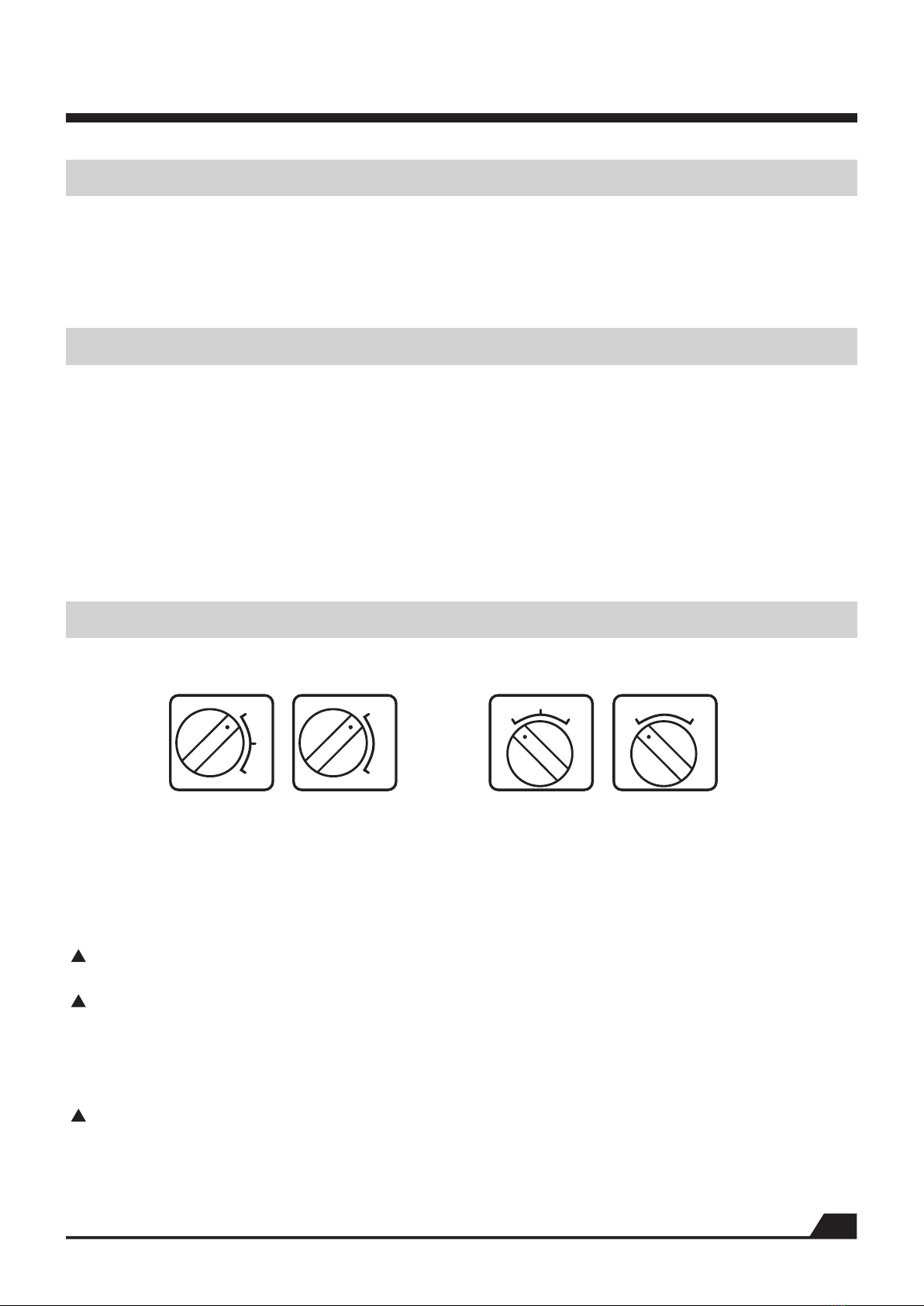
17.The type of generator speed adjustment or gear speed adjustment in work please
select the adaptive bit of appearance, and open speed most quickly, so machine
reach best state. If rig in working process rock , must close machine to inspect the
concentric degree of bit and main shaft , can damage machine otherwise to occur
danger.
18.Pay attention: For your personal benefit, please choose original factory accessory
Is not original factory accessory if choosing , will may produce injury for operator
or the very machine.
Follow the steps to installing and connecting.You can use additional tool .To
complete the following work.
Pay attention: Before joining , must guarantee that the switch of main
computer is in the state that stops.
Step 1: Comparing with the inspection of container load plan, machine and parts
open package, inspect machine in transportation process, whether damage ,
inspection the voltage of building site whether the voltage that shows on nameplate
is consistent, contrast container load plan sees the attachment in package whether is
complete.
Step 2: Power source joins , according to a standard EN61029 and a IEC1029-2 6
of European Union, taking the diamond drilling machine of water schoolwork must
add to pack the protector of leakage of electricity ,the socket of power source must
carry out earthing. It is consistent with these safe rules, our product matches have
packed the protector of leakage of electricity, its function ,including leakage of
electricity are protected untie with under-voltage to deduct. Insert the plug of power
source well after, the switch face plate of the protector of leakage of electricity must
ensure that is in ON ( beginning ) location.Fall if arising voltage drop, the protector
of leakage of electricity will automatic everything breaks , once after voltage normal,
should operate the protector of leakage of electricity again in REST cubes ( reset )
location. The protector of leakage of electricity specified movement current is 30mA.
Pay attention: Quote clean source of water surely , contain grit waiting for until
the water of impurity may damage the water set sealing ring of machine, 3biggest
hydraulic pressure is 3BAR.
PREPARATORY STAGE

6
Step 3: Source of water joins , the radom ware additional water inlet of flaxible
tube holds to have " fast joint" may join to wire reinforced suction hose very
conveniently on water supply system.
Pay attention: If the protector function of leakage of electricity is not normal ,
please do not want manipulator ware.
Step 4: Safety is tested , pressing generator switch and machine ( soft start
switch ) start smoothly. Press the protector button of leakage of electricity of " test ",
machine stops operation , then resumes the power supply for machine again
according to the button of " reset ".
Pay attention: Must cannot soak the protector of leakage of electricity in water.
Must often pass according to press TEST button, come to inspect its function whether
is normal. Suggesting operator not to operate do not take the diamond drilling
machine of the protector of leakage of electricity.
BEGIN TO OPERATE
1、Choose suitable diamond bit
The silk of main shaft of our company deducts 4 kinds uses type frequently,
please choose the reliable diamond bit of quality. Choose sharp tool , ! And ensure
that segement is first to have enough backlash( the thickness of segement the thic-
kness that is larger than tube wall , such do good to more in row bits) between me-
tal tube wall. It is above that using waterproof oil paint in the silk of bit to deduct,
in order to make dismantling bit convenient. Ensure bit way jump do not be larger
than 1 mm( eccentricity).
2、Fix frame in face
Regular method has expansion bolts to fix ; vacuum sucker is fixed ; supports
regular etc..
The most general method is fixed for expansion bolt, please use the diameter
of metal expansion bolt and bolt as far as possible, must be larger than 12 mm.
Using vacuum sucker fix , ensure that vavuum pump has enough efficiency,sealing
ring complete have no breakage. Adopting support ensure when fixing way that
frame has enough stability.
Fix using expansion screw regular way, first, will guarantee that face and the
base of machine will be balanced , if have , it is high! Please use the spanner that
takes in machine attachment for low injustice,the 4 adjustment screws on
regulation base are balanced till base. After being fixed completely, machine
should guarantee that generator will not slide on rack. And will make efforts
around around pull to move pillar , will guarantee that when pillar is not around ,
sway side may use machine.
Pay attention: Our company suggests to use expansion bolt regular way to fix
vigorously, and the location of expansion screw lets egg to pillar direction to be
near is best. Since fixing consequence our company that not causes firmly , do not
undertake any duty.
Vertical upward drill hole, must ensure special turn water to obtain basin , gua-
rd against generator strictly cannot enter water. In working error any suspension,
open only to start machine road can.Ensure to take the charge of machine fear sta-
rt former bit may turn freely.Is not blocked in hole.

7
FRICTION CLUTCH
Clutch carries out protection under high-strength mechanical overload
condition for operator, machine and bit. Please ensure clutch in a separation state
goes off work to do do not exceed 3-4 second, because it will cause temperature
rise quickly and causes wear for friction flat that time passes length.
MASTER SWITCH AND OVERLOAD PROTECTIVE DEVICE
After pressing switch, machine ( soft start switch ) starts smoothly.If machine
is overload, its electron protects switch, will remind operator machine to be
overload with exceptional fluctuation. If load does not be reduced , after some
seconds of clocks, switch is closed voluntarily. Start again if remove load, machine
will again start smoothly. When start machine again is former, ensure bit may turn
freely is not blocked in drill hole. It will even burn out for that generator causes
serious infringement if this machine highest compression is higher than 260 V for
260 V. When using generator to supply power , must notice that voltage peak value
cannot be higher than 260 V.
GEAR SPEED ADJUSTMENT
H
M
L
H
LH H
M
L L
Ordinary gear speed adjustment Oil soaks money gear speed adjustment
3 files 3 files 2 files2 files
To improve the efficiency of drilling, some machines have 3 type gear speed chang-
es. In it is high to divide , high speed files ( the day files ) apply to little bit and more
soft material to rush , fast files ( M files ) apply to in bit and more hard material; The
files of low speed ( L files ) apply to big bit and hard material.
Machine turns under stoping the state that turns or stops soon to move group chan-
ge files.
Machine must want to shift gear to position when shifting gear , if occur main shaft
after start,it does not turn or have tooth sound to explain that files position does
not hang to position , must close switch at once, and turn again move knob to the
position that needs files at the same time round trip turns main shaft ( hang files
easily ), have obvious put into gear to block until position.
Must close mains switch at once, round trip turns mainshaft to at the same time
turn to move knob. Machine is operating at full speed, load or card please don't
change files when living.

8
L is the files of low speed, H is high speed files, M is the files of middling speed
( 3 files types), graphic representation is the files of low speed, spin along hour
hand if by the files of low speed, turning high speed files knob, otherwise
counter-clockwise.
COMMON FAULT AND THE METHOD OF REMOVING
Fault Reason The method of removing
Generator
does
not
turn
Power source is obstructed ,
or contacts to loosen to fall
Carbon brush blocks ,
take off open commutator
After the protector movement of
leakage of electricity, do not reset
The protector damage of
leakage of electricity
Bit life has arrived
Feed pressure is too low
Bit knife first surface is pasted
by thin bits
Rotational speed is too high
It is slippery to cut thick reinforcing
bar to hit
In processing hole, amass bits
Current does not be obeied , leakage
or have no reflux
Bit sharp degree reduces
The leather or broken bits piece of
reinforcing bar blocks , is geting into
core between bit or between bit and
hole wall, frame fixes , is not firm , it is
exceptional to produce displacement
frame pillar and the gap of sliding
sleeve.
Stop machine , turn bit around spanner, or pull out bit
to knock broken get into heart to fix the frame
adjustment gap of sliding sleeve again.
Drill hole
is too
slow
Bit
blocks
Bit wall
wear is
rapid
Water set
leakage
Resume power source , inspect all joints and tighten
New installation carbon brush
Press reset button to start generator again
Change the protector of leakage of electricity
Change bit
Increase feed pressure
Clean bit, increase hydraulic pressure
Switch the files position of low speed
Feed pressure reduces is little after,will cross reinforcing
bar increase pressure again
Put in order hole bottom. Pressurization
Inspect into the valve of water polo , inspect current
Using fire-resistant brick or emery wheel open edge again
Main shaft not just
Bit not just
Reinforcing bar or thin bits can not
remove hole outside
The skeleton wear or ageing of sealing
ring
Repair or change main shaft
Change bit
Improvement current, take out bit , clean hole
Change skeleton sealing ring

9
MAINTENANCE AND REPAIR
ATTENTION: You must remove the main plug from the supply socket before beginning
any maintenance or repair work.
Clean the machine with a dry or moist cheaning-rag and not with a jet of water. Make sure
that no water gets into the motor or the switch box. Ensure that the ventilation slots are always
clean. Clean and greases the tool thread , too.
Oil bath gear
The gear oil should be changed after 300 hours of operation. Ensure that this work is carried
out in a specialist workshop, or proceed as follow: Clamp the machine vertically in the vice. Rem-
ove the three hexagon socket screws. Take off motor and inter-mediate cover. Change gear oil-
use only original oil. The filling quantity is 300-310ml.To reassemble, proceed vice vesa and ens-
ure that the shim ring is on the front shaft.
ATTENTION: if gear oil escapes, stop the machine immediately. Leakage of oil damages
the gear. Water connection
If water escapes from the overflow hole on the water connection ring, the rotary shaft seals
must be replace immediately. This should only be done in an authorized specialist workshop.
Carbon brushes
The carbon brushes should be examined for wear after about 300 hours in operation, and
replaced if necessary. As with all other work on the motor, this should only be carried out by an
electrician.
WARRANTY
We warrants all products manufactured or sold by it against defects in workmanship or
materials for period of 12 months from the date of shipment to the customer. Please contact
our factory or the authorized repair shop in your local area for replacement or repair of
defective parts.
This warranty does not cover normal wear and tear, overloading , non-compliance with the
operating instruction and intervention by unauthorized persons or the use of parts from other
companies.
※We don't warranty the situation that machine is not fixed by users and damaged.

1 0

1 1
1
2
3
4
5
6
7
8
9
10
11
12
13
14
15
16
17
18
19
20
21
22
23
24
25
26
27
28
29
30
31
32
33
34
35
36
37
38
39
40
41
42
43
44
45
46
47
48
49
50
51
52
53
Water seal 40 * 50 * 7
Hegonal screw M5 * 18
Water circle 200C
Hose faucet 200A-EU
Spindle KF-200
Bearing 6201
Class I tooth axis 180-2
Marketing 4 * 10
Class I gear 200C-1(8)
Bearing 6201
Middle cover 200C-1
O-ring φ 34.5 * 2.65
Bearing 6201
Nut 200
Iron Ring 200-2
Curved bullet pad 200A
Flesh iron 200A
Separation film 200A
Class II gear 180-3
Ring 250
Bearing 6201
Class II tooth axis 180-4
Card 22
Spindle gear 250-5
Card 24
Cylinder pin 4 * 12
Hegonal screw M6 * 85(half tooth)
Gear box 200C-1
Bearing 6005
Inner card 47
Hegonal screw M6 * 110(half tooth)
Pad M6
Pad M6
Bearing 6202
Rotor OND-920
Bearing 6201
Breeze 200C
Loose nut M5
Pad M5
Hegonal screw M5 * 105(half tooth)
Interior 200C
Insulation sleeve 200A
Stator OND-920
O-ring φ 38 * 3.1
Business Sign 200C
Stator hull 200C
Cross level screw M4 * 8
Parameter card OND(58.5 * 36.5)
Brush frame 200C
Bypass 200A
Round Head Cross Screw M4 * 8(Copper)
Carbon Brush 200A
Cover 200C
2
3
1
1
1
1
1
1
1
1
1
1
1
1
1
2
2
2
1
1
1
1
1
1
1
1
2
1
2
1
2
4
4
1
1
1
1
2
2
2
1
2
1
2
1
1
1
1
1
2
2
2
1
1
2
1
1
1
4
1
1
1
1
Horizontal 15 * 8
Hegonal screw M4 * 10
Switch Box 200A-FS
Button head SKT-10
Fold proof connector M16 * 1.5
Hegonal screw M4 * 45(half tooth)
Switch Box Cover 200A-FS
Electromagnetic switch KJD17
Power cord 3 * 1.0 * 3.5 M
Leakage protector PD16
54
55
56
57
58
59
60
61
62
63
NO. Parts name QTY NO. Parts name QTY

1 2
OND-920

1 3
1
2
3
4
5
6
7
8
9
10
11
12
13
14
15
16
17
18
19
20
21
22
23
24
25
26
27
28
29
30
31
32
33
34
35
36
37
38
39
40
41
42
43
44
45
46
47
48
49
50
51
52
53
Water seal 40 * 50 * 7
Hose faucet 200A-EU
Hegonal screw M5 * 18
Watershed 250C
Main axis 230 tune
Bearing 6202
Class II gear axis 250A/2 -6(14)
Ball head plunger M8 * 15
Type II High Speed Gear 250A/2 -5
Stop Ring 18
Class II sliding gear 250A/2 -4
Type II low-speed gear 250A/2 -3
Card 16
Bearing 6201
Middle cover 250C
Roller bearings BAM1212
Nut 200A
Ring 250
Curved bullet pad 200A
Flesh iron 200A
Spindle gear 250A-5(14)
Separation film 200A
Hand-key pad 250A
Hegonal screw M6 * 125(half tooth)
Gear box 250C
Bearing 3205
Inner card 52
Hegonal screw M6 * 135(half tooth)
Pad M6
Pad M6
File plate 250A/2
Cylinder pin 4 * 12
Stop ring φ 40
Cylinder pin 5 * 28
O-ring φ 42 * 3.1
Dialing knob 250C
Bearing 6201
Class I tooth axis 250A/2 -2
Marketing 4 * 10
Class I gear 250C-1(8)
Bearing 6201
O-ring φ 34.5 * 2.65
Breeze 200C
Bearing 6202
Rotor OND-930 / 2E
Bearing 6201
Loose nut M5
Pad M5
Hegonal screw M5 * 105(half tooth)
Stator inner liner 200C
Insulation sleeve 200A
Stator OND-930 / 2E
O-ring φ 38 * 3.1
2
1
3
1
1
1
1
1
1
1
1
1
1
1
1
1
1
1
5
2
1
2
1
2
1
1
1
2
4
4
1
1
1
1
1
1
1
1
1
1
1
1
1
1
1
1
2
2
2
1
2
1
1
1
1
1
1
1
2
1
2
2
1
1
2
4
4
1
1
1
1
1
1
1
1
1
4
1
1
1
Business Sign 200C
Stator hull 200C
Cross level screw M4 * 8 white
Parameter card OND(58.5 * 36.5)
Fold proof connector M16 * 1.5
Carbon Brush 200A
Brush frame 200C
Bypass 200A
Round Head Cross Screw M4 * 8(Copper)
Cover 200C
Horizontal instrument φ 15 * 8
Hegonal screw M4 * 10
Pad M5
Hegonal screw M5 * 10
Curved handle 200D
Power cord 3 * 1.5 * 3.5 M
Leakage protector PD16
Round Cross Screw M4 * 10
Governor SCY20504050(A)
Speed control knob KN-8D
Electromagnetic switch KJD17
Speed adjustment label SCY
Hegonal screw M4 * 25
Hegonal screw M4 * 50(half tooth)
Switching box cover 200A-T-FS
Button head SKT-10
Switch Box 200A-T-FS
NO. Parts name QTY NO. Parts name QTY
54
55
56
57
58
59
60
61
62
63
64
65
66
67
68
69
70
71
72
73
74
75
76
77
78
79
80

1 4
OND-930/2E

1 5
1
2
3
4
5
6
7
8
9
10
11
12
13
14
15
16
17
18
19
20
21
22
23
24
25
26
27
28
29
30
31
32
33
34
35
36
37
38
39
40
41
42
43
44
45
46
47
48
49
50
51
52
53
Water seal 40 * 50 * 7
Hose faucet 200A-EU
Hegonal screw M5 * 18
Watershed 250C
Main axis 230 tune
Bearing 6202
Class II tooth axis 250A/3 -6(12)
Ball head plunger M8 * 15
Type II High Speed Gear 250A/3 -5
Stop Ring 18
Class II sliding gear 250A/3 -4
Type II low-speed gear 250A/3 -3
Card 16
Bearing 6201
Middle cover 250C
Roller bearings BAM1212
Nut 200A
Ring 250
Curved bullet pad 200A
Flesh iron 200A
Host gear 250A-5(12)
Separation film 200A
Hand-key pad 250A
Hegonal screw M6 * 125(half tooth)
Gear box 250C
Bearing 3205
Inner card 52
Hegonal screw M6 * 135(half tooth)
Pad M6
Pad M6
File plate 300A/3
Cylinder pin 4 * 12
Stop ring φ 40
Cylinder pin 5 * 28
O-ring φ 42 * 3.1
Dialing knob 250C
Bearing 6201
Class I tooth axis 250A/3 -2
Marketing 4 * 10
Class I gear 250C-1(8)
Bearing 6201
O-ring φ 34.5 * 2.65
Breeze 200C
Bearing 6202
Rotor OND-935 / 3E
Bearing 6201
Loose nut M5
Pad M5
Hegonal screw M5 * 105(half tooth)
Interior 200C
Insulation sleeve 200A
Stator OND-935 / 3E
O-ring φ 38 * 3.1
2
1
3
1
1
1
1
1
1
1
1
1
1
1
1
1
1
1
5
2
1
2
1
2
1
1
1
2
4
4
1
1
1
1
1
1
1
1
1
1
1
1
1
1
1
1
2
2
2
1
2
1
1
1
1
1
1
1
2
1
2
2
1
1
2
4
4
1
1
1
1
1
1
1
1
1
4
1
1
1
Business Sign 200C
Stator hull 200C
Cross level screw M4 * 8 white
Parameter card OND(58.5 * 36.5)
Fold proof connector M16 * 1.5
Carbon Brush 200A
Brush frame 200C
Bypass 200A
Round Head Cross Screw M4 * 8(Copper)
Cover 200C
Horizontal instrument φ 15 * 8
Hegonal screw M4 * 10
Pad M5
Hegonal screw M5 * 10
Curved handle 200D
Power cord 3 * 1.5 * 3.5 M
Leakage protector PD16
Round Cross Screw M4 * 10
Governor SCY20504050(A)
Speed control knob KN-8D
Electromagnetic switch KJD17
Speed adjustment label SCY
Hegonal screw M4 * 25
Hegonal screw M4 * 50(half tooth)
Switching box cover 200A-T-FS
Button head SKT-10
Switch Box 200A-T-FS
NO. Parts name QTY NO. Parts name QTY
54
55
56
57
58
59
60
61
62
63
64
65
66
67
68
69
70
71
72
73
74
75
76
77
78
79
80

1 6
OND-935/3E

This manual suits for next models
78
Table of contents
Other Cayken Drill manuals