CCOM NIC-EBS/L/V User manual

NIC-EBS/L/V/i
Network managed G.703 to Ethernet Converter
Installation and Operation Manual
Code:C047b-004-00
HW: C047-100-20 C047b-100-21
HW: C049-100-20 C049-101-00
HW: C049-100-21 C049b-100-21 C049-101-01
SW:SC047-100-20

NIC-EBS/L/V/iInstallationandOperationManual
CCOM Communication Technology Co.Ltd. Http://www.ccom.com.cn Page 2 of 32
Notice
This manual contains information that is proprietary to CCOM Communication Technology Co.Ltd. No part of this
publication may be reproduced in any form whatsoever without prior written approval by CCOM.
No representation or warranties for fitness for any purpose other than what is specifically mentioned in this
manual is made either by CCOM Co. Ltd. Or its agents.
CCOM Keep the further expository and amending right for the manual.
For further information contact CCOM Communications at the address below or contact your local distributor.
CCOM Communications Technology Co.,Ltd.
First unit, No.1 building, Part A,
Zhaowei industry park, No.14 Jiuxianqiao road, Chaoyang district, Beijing, China
Postalcode:100016
TEL:86-10-64360088
FAX:86-10-64378389

NIC-EBS/L/V/iInstallationandOperationManual
CCOM Communication Technology Co.Ltd. Http://www.ccom.com.cn Page 3 of 32
Warranty
This CCOM product is warranted against defects in material and workmanship for a period of one year from date of
shipment. During the warranty period, CCOM, will, at is option, either repair or replace products which prove to be
defective. For warranty service or repair, this product must be return to a service facility designated by CCOM.
Limitation of Warranty
The foregoing warranty shall not apply to defects resulting from improper or inadequate maintenance by Buyer,
Buyer-supplied firmware or interfacing, unauthorized modification or misuse, operation outside of the environmental
specifications for the product, or improper site preparation or maintenance.
General Safety Precautions
Transportation, Installation and Operation
Avoid excessive vibration and shocks.
Avoid contact with water, dust, and dirt.
Avoid excessive direct sunlight.
Ensure sufficient cooling.
Prevent loose items from falling into the device.
Main Powers
Disconnect the power cord before opening the device.
Use exclusively the supplied power supply the approved power cord.
The power plug must be plugged into a properly grounded receptacle. An improperly wired receptacle could place
hazardous voltage on accessible metal parts of the device.
The mains supply must match the power specification of the device.
Replace blown fuses exclusively with fuses of the same ratings.
Do not work on the equipment during periods of lightning activity.
Technical Support
Before contacting with your support representative, please prepare to provide the complete serial number of the affected
unit (refer to the according unit label).
Version Number
DATE Version Describe

NIC-EBS/L/V/iInstallationandOperationManual
CCOM Communication Technology Co.Ltd. Http://www.ccom.com.cn Page 4 of 32
Content
1Chapter 1 Introduction......................................................................... 8
1.1 Overview..............................................................................................................................8
1.2 Versions...............................................................................................................................8
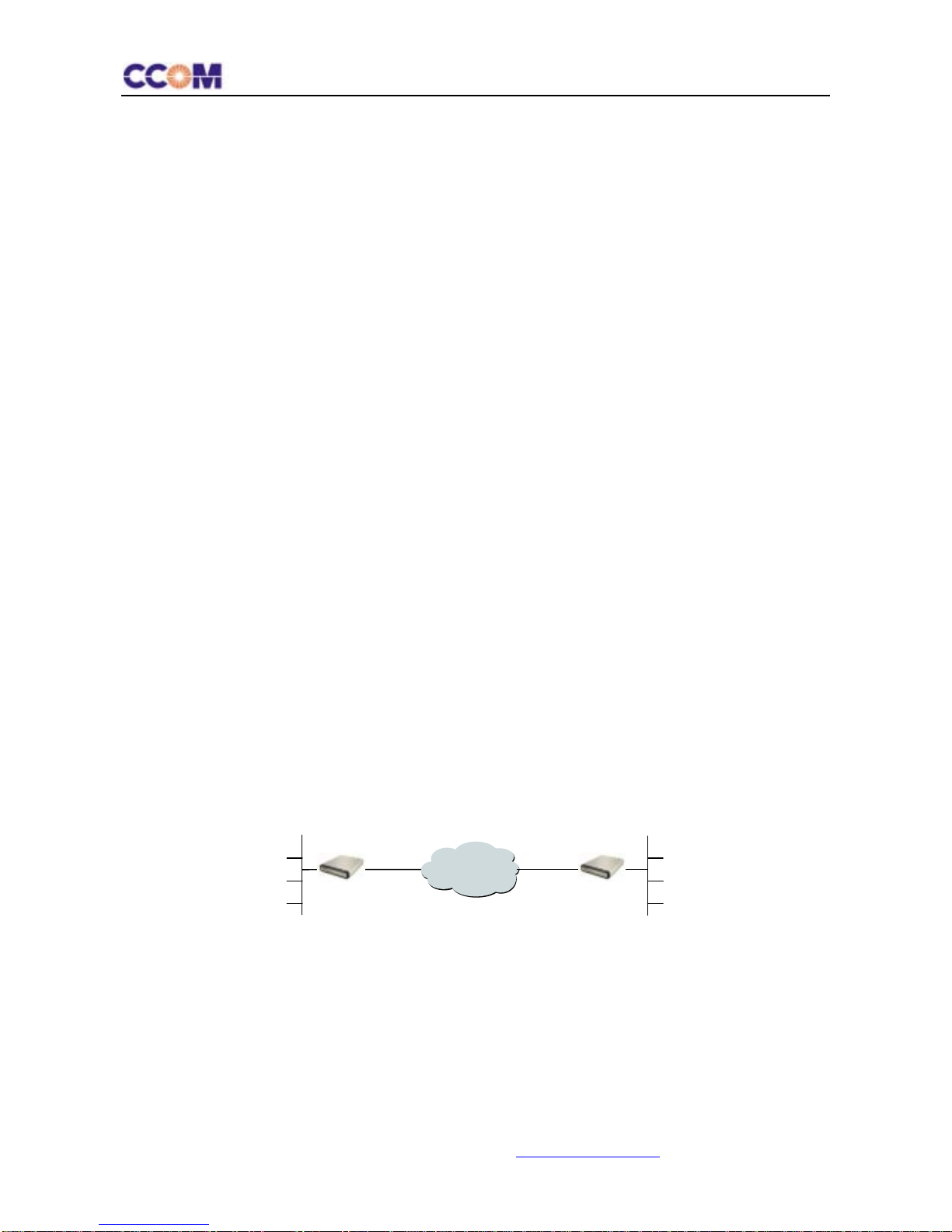
1.3 Applications .........................................................................................................................8
1.4 Features...............................................................................................................................9
1.5 Physical Description............................................................................................................9
1.5.1 Front Panel of Stand Alone Unit...............................................................................................9
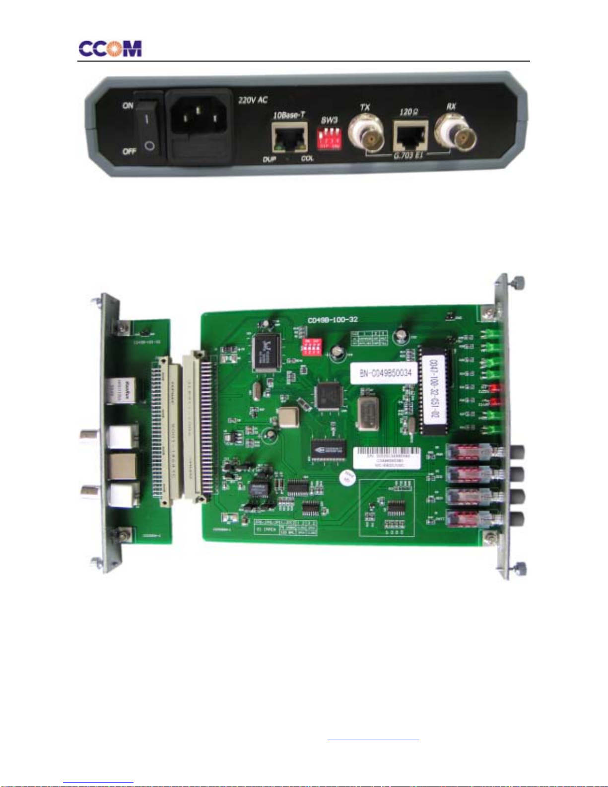
1.5.2 Rear Panel of Stand Alone Unit ................................................................................................9
1.5.3 Card Product ...........................................................................................................................10
1.6 Technical Specifications....................................................................................................10
1.6.1 E1 Interface.............................................................................................................................10
1.6.2 Ethernet interface....................................................................................................................11
1.6.3 Physical...................................................................................................................................13
1.6.4 Power Supply..........................................................................................................................13
1.6.5 Environment ...........................................................................................................................14
1.6.6 MTBF .....................................................................................................................................14
2Chapter 2 Installation and Setup ....................................................... 15
2.1 Site Requirements and Prerequisites................................................................................15
2.2 Configuration.....................................................................................................................15
2.3 Installation and Setup of Standalone Unit.........................................................................17
2.3.1 To install NIC-EBS/L/V/i: ......................................................................................................17
2.3.2 Connecting the Interfaces .......................................................................................................17
2.3.3 Connecting the Power.............................................................................................................19
2.4 Installation and Setup of Card Unit ...................................................................................20
2.4.1 Installing the Card Unit into the NIC-iRACK Card Cage ......................................................20
2.4.2 Connecting the Interfaces .......................................................................................................20
3Chapter 3 Operation.......................................................................... 21
3.1 Front Panel Indicators and Controls..................................................................................21
3.2 Operating Procedure.........................................................................................................22
3.2.1 Turning NIC-EBS/L/V/i On....................................................................................................22
3.2.2 Normal Indications .................................................................................................................22
3.2.3 Turning NIC-EBS/L/V/i Off...................................................................................................22
3.3 Loopback Test...................................................................................................................22
3.3.1 Local Analog Loopback (ANA)..............................................................................................23
3.3.2 Local Digital Loopback (DIG)................................................................................................23
3.3.3 BER Test (L/R) .......................................................................................................................23
3.4 SNMP Network Management............................................................................................25
3.4.1 SNMP Management Topology................................................................................................25
3.4.2 Main Function.........................................................................................................................25

NIC-EBS/L/V/iInstallationandOperationManual
CCOM Communication Technology Co.Ltd. Http://www.ccom.com.cn Page 5 of 32
3.4.3 SNMP Management................................................................................................................26
4Chapter 4 Troubleshooting................................................................ 29
5Supplement Pinouts .......................................................................... 31

NIC-EBS/L/V/iInstallationandOperationManual
CCOM Communication Technology Co.Ltd. Http://www.ccom.com.cn Page 6 of 32
Figure Index
FIGURE 1-1 POINT-TO-POINT APPLICATION .......................................................................................................................... 8
FIGURE 1-2 FRONT PANEL OF STAND ALONE UNIT .............................................................................................................. 9
FIGURE 1-3 REAR PANEL OF STAND ALONE UNIT .............................................................................................................. 10
FIGURE 1-4 CARD UNIT ..................................................................................................................................................... 10
FIGURE 2-1 DIP SWITCHES OF STAND ALONE UNIT........................................................................................................... 16
FIGURE 2-2 DIP SWITCHES OF CARD UNIT ........................................................................................................................ 16
FIGURE 2-3 REAR PANEL OF STAND-ALONE UNIT (AC VERSION) ....................................................................................... 17
FIGURE 2-4 REAR PANEL OF STAND-ALONE UNIT (DC VERSION) ....................................................................................... 18
FIGURE 2-5 E1 CONNECTORS ............................................................................................................................................. 18
FIGURE 2-6 DC POWER CONNECTION ................................................................................................................................19
FIGURE 2-7 NIC-IRACK FOR CARD UNITS ........................................................................................................................ 20
FIGURE 2-8 REAR PANEL OF CARD UNIT............................................................................................................................. 20
FIGURE 3-1 FRONT PANEL OF STANDALONE UNIT ............................................................................................................. 21
FIGURE 3-2 FRONT PANEL OF CARD UNIT.......................................................................................................................... 21
FIGURE 3-3 LOCAL ANALOG LOOPBACK ........................................................................................................................... 23
FIGURE 3-4 LOCAL DIGITAL LOOPBACK ............................................................................................................................ 23
FIGURE 3-5 BER SYSTEM SINGLE-UNIT TEST.................................................................................................................... 24
FIGURE 3-6 BER SYSTEM TWO-BER TEST ....................................................................................................................... 24
FIGURE 3-7 NETWORK TOPOLOGY..................................................................................................................................... 25

NIC-EBS/L/V/iInstallationandOperationManual
CCOM Communication Technology Co.Ltd. Http://www.ccom.com.cn Page 7 of 32
Table index
TABLE 1-1 E1 INTERFACE SPECIFICATION.......................................................................................................................... 10
TABLE 1-2 OUTPUT JITTER OF E1 PORT ............................................................................................................................. 11
TABLE 1-3 INPUT JITTER OF E1 PORT................................................................................................................................. 11
TABLE 1-4 JITTER TRANSFER CHARACTERISTIC OF E1 PORT ............................................................................................. 11
TABLE 1-5 ETHERNET INTERFACE SPECIFICATION ............................................................................................................. 11
TABLE 1-6 LAN PORT WORKING MODE WHEN COOPERATING WITH PERIPHERAL EQUIPMENTS.......................................... 12
TABLE 1-7 THROUGHPUT TEST.......................................................................................................................................... 12
TABLE 1-8 PACKET LOSS TEST.......................................................................................................................................... 12
TABLE 1-9 LATENCY TEST ................................................................................................................................................ 13
TABLE 1-10 BACK-TO-BACK TEST ................................................................................................................................... 13
TABLE 1-11 PHYSICAL SPECIFICATION .............................................................................................................................. 13
TABLE 1-12 POWER SUPPLY SPECIFICATION ...................................................................................................................... 13
TABLE 1-13ENVIRONMENT................................................................................................................................................ 14
TABLE 2-1 SW3 OF STAND ALONE UNIT ............................................................................................................................ 16
TABLE 2-2 SWITCHES OF CARD UNIT ................................................................................................................................. 17
TABLE 3-1 FRONT PANEL INDICATORS AND CONTROLS .................................................................................................... 21
TABLE 4-1. TROUBLESHOOTING PROCEDURE .................................................................................................................... 29
G.703 120ΩRJ-45 CONNECTER PINOUTS ..................................................................................................................... 31
ETHERNET RJ-45 CONNECTER PINOUTS........................................................................................................................ 31
RJ-45 PINOUTS FOR CAT 5EIA/TIA-568-A ................................................................................................................... 31
RJ-45 PINOUTS FOR CAT 5EIA/TIA-568-B ................................................................................................................... 31

NIC-EBS/L/V/iInstallationandOperationManual
CCOM Communication Technology Co.Ltd. Http://www.ccom.com.cn Page 8 of 32
1 Chapter 1 Introduction
1.1 Overview
NIC-EBS/L/V/i is a type of high quality Ethernet-to-E1 converter. As an extended equipment of Ethernet, it could be
used to connect two Ethernets transparently by PDH or SDH network and adapt to found remote network connection
with a low cost.
NIC-EBS/L/V/i has 1 10/100Base-T Ethernet interfaces with auto-negotiation function on Full/Half Duplex and
10/100M speed.
NIC-EBS/L/V/i can learn the MAC address automatically that be connected and transmit just the datagram with the
destination address in the remote Ethernet. So it can restrain the broadcast and advance the efficiency of the Ethernet.
The transmitting speed is up to 2.048Mbps.
Twin using of NIC-EBS/L/V/i at the application is suggested.
1.2 Versions
The following versions of the unit are available:
¾NIC-EBS/L/V/i/AC: a standalone unit, AC power supply.
¾NIC-EBS/L/V/i/48: a standalone unit, -48VDC power supply.
¾NIC-EBS/L/V/i/24: a standalone unit, +24VDC power supply.
¾NIC-EBS/L/V/i/C: a plug-in card unit consisting of a front sub card and a back sub card for installation in the
NIC-iRACK, 19-inch rack, holding up to 14 service cards.
1.3 Applications
Figure 1-1 Point-to-Point application
E1 Network
NIC-EBS/L/V/i
LAN
NIC-EBS/L/V/i

NIC-EBS/L/V/iInstallationandOperationManual
CCOM Communication Technology Co.Ltd. Http://www.ccom.com.cn Page 9 of 32
1.4 Features
¾Standard: IEEE 802.3, 802.3u, 802.1Q, 802.1x, ITU-T G.703, G.742, G.823
¾Unframed Speed: 2048K Bit/s
¾Support SNMP network management through central card unit fixed in NIC-iRACK
¾E1 connector: 75BNC/120RJ-45
¾Ethernet Interface: RJ-45 jack, 10 /100Base-T interface, auto MDI-X
¾Auto negotiation or force mode on Full/Half Duplex mode and 10/100M speed
¾Support VLAN trunk and flow control functions
¾Loop test function: ANA, DIG, REM
¾Power supply: 90~220VAC, -36~-72VDC, +18~+36VDC
¾Card style or stand alone style
1.5 Physical Description
NIC-EBS/L/V/i is available as a standalone unit or as a rack-mount card for the NIC-iRACK.
1.5.1 Front Panel of Stand Alone Unit
Figure 1-2 Front Panel of Stand Alone Unit
The front panel includes 8 LEDs, which display the status of power, data flow, Ethernet link and E1 channel signal.
Four front-panel push-buttons control 3 kinds of loopbacks and the display of remote Ethernet interfaces. For detailed
description of the front panel, see Chapter 3.
1.5.2 Rear Panel of Stand Alone Unit

NIC-EBS/L/V/iInstallationandOperationManual
CCOM Communication Technology Co.Ltd. Http://www.ccom.com.cn Page 10 of 32
Figure 1-3 Rear Panel of Stand Alone Unit
The back panel includes a power connector (AC or DC),a power switch, 4 Ethernet interface connectors, S3 DIP-switch
and a E1 line connector. The NIC-EBS/L/V/i rear panel is described in greater detail in Chapter 2.
1.5.3 Card Product
Figure 1-4 Card Unit
1.6 Technical Specifications
1.6.1 E1 Interface
Table 1-1 E1 interface specification

NIC-EBS/L/V/iInstallationandOperationManual
CCOM Communication Technology Co.Ltd. Http://www.ccom.com.cn Page 11 of 32
Standard ITU-T G.703, G.704, G.823 and G.742
Framing Framed/Unframed
connector BNC male connector for 75coaxial cables;
RJ-45 jack for 120twisted pairs
Code HDB3
Baud rate 2048 Kbps ±50ppm
Bit rate Unframed: 2.048M bps
Framed: N*64k (N<=31)
Impedance 75for unbalanced (BNC, coaxial cable)
120for balanced (RJ-45, twisted pair)
Receiving sensitivity 0~-18dBm
Transmit high voltage 2.37V±10%, 75; 3.00V±10%,120
Transmit low voltage 0 ± 0.1V
Transmitting distance 100m for coaxial cable, 300m for twisted-pair
Table 1-2 Output Jitter of E1 port
B1(20Hz~100KHz) <0.08 UI
B2(18kHz~100KHz) <0.05 UI
Table 1-3 Input Jitter of E1 port
Frequency(Hz) 10 20 63 130 500 1.2k 2.1k 3.7k 6.4k 11k 100k
Jitter (UI) 30.7 30 26.7 14.6 6.04 4.22 3.83 3.7 3.1 2.8 0.7
Table 1-4 Jitter Transfer characteristic of E1 port
Frequency(Hz) 20 45 65 130 260 500 1.2k 2.1k 100k
Jitter(UI)-35.97 -42.71 -56.82 -64.43 -57.63 -57.50 -54.37 -55.12 -52.31
1.6.2 Ethernet interface
Table 1-5 Ethernet interface specification
Function support VLAN trunk and flow control
Standard IEEE 802.3 802.3u 802.1q
Interface Ethernet and Fast Ethernet
Link Speed 10/100Mbit/s, Auto-Negotiation/force mode
Duplex Mode force or Auto-Negotiation on Half / Full Duplex Mode
Connector RJ-45 jack, auto MDI-X
Frame Length 64byte(least)/1536byte(most)
MAC Address Capacity 1K
MAC Address Update 5 Minutes

NIC-EBS/L/V/iInstallationandOperationManual
CCOM Communication Technology Co.Ltd. Http://www.ccom.com.cn Page 12 of 32
Table 1-6 LAN port working mode when cooperating with peripheral equipments
LAN port setting
mode
peripheral equipments
setting mode
LAN port real working
mode
peripheral equipments real
working mode
Effect
A/N A/N 100M FD 100M FD perfect
100M FD 100M FD 100M FD 100M FD perfect
10M FD 10M FD 10M FD 10M FD perfect
100M HD 100M HD 100M HD 100M HD perfect
10M HD 10M HD 10M HD 10M HD perfect
A/N 100M HD 100M HD 100M HD good
A/N 10M HD 10M HD 10M HD good
A/N 100M FD 100M HD 100M FD unfitting
A/N 10M FD 10M HD 10M FD unfitting
NOTE: A/N(auto-negotiation) FD(full duplex) HD(half duplex)
Table 1-7 Throughput Test
Frame Size Passed
Rate(%)
01 to 02
(pks/sec)
02 to 01
(pks/sec) Total
100M -100M 100M -100M
64 100.00 148810 148810 297620
128 100.00 84459 84459 168918
256 100.00 45290 45290 90580
512 100.00 23496 23496 46992
1024 100.00 11973 11973 23946
1280 100.00 9615 9615 19230
1518 100.00 8127 8127 16254
1536 100.00 8033 8033 16066
Table 1-8 Packet Loss Test
Frame Size Rate Tested(%) 01 to 02 (%) 02 to 01 (%) Average
100M -100M 100M -100M
64 100.00 0.000 0.000 0.000
128 100.00 0.000 0.000 0.000
256 100.00 0.000 0.000 0.000
512 100.00 0.000 0.000 0.000
1024 100.00 0.000 0.000 0.000
1280 100.00 0.000 0.000 0.000
1518 100.00 0.000 0.000 0.000
1536 100.00 0.000 0.000 0.000

NIC-EBS/L/V/iInstallationandOperationManual
CCOM Communication Technology Co.Ltd. Http://www.ccom.com.cn Page 13 of 32
Table 1-9 Latency Test
Table 1-10 Back- to-Back Test
Frame Size Rate Tested(%) 01 to02 Burst Size
(frames) 02 to01 (frames) Total
100M -100M 100M -100M
64 100.00 297620 297620 595240
128 100.00 168918 168918 337836
256 100.00 90580 90580 181160
512 100.00 46992 46992 93984
1024 100.00 23946 23946 47892
1280 100.00 19230 19230 38460
1518 100.00 16254 16254 32508
1536 100.00 16066 16066 32132
1.6.3 Physical
Table 1-11 Physical specification
Height Width Depth Weight
Stand-alone 44 mm/1.73 inch 197 mm / 7.76 inch 230 mm / 9.06 inch 1.1kg
Card 144mm/5.67 inch 28mm/1.10 inch 250mm/9.84 inch 0.3kg
Package 280mm/11.02 inch 310mm/12.20 inch 80mm/3.15 inch 1.0kg
NIC-EBS/L/V/i/C Card Fit one slot in the NIC-iRACK card cage
1.6.4 Power Supply
Table 1-12 Power supply specification
165~265 VAC, 50Hz, 5W, 1A fuse
Frame Size Rate Tested(%) 01 to 02 (us)-CT Average (CT) 01 to 02 (us)-S&F Average (S&F)
100M -100M 100M -100M
64 100.00 100.3 100.3 95.1 95.1
128 100.00 110.6 110.6 100.4 100.4
256 100.00 131.1 131.1 110.6 110.6
512 100.00 172.0 172.0 131.1 131.1
1024 100.00 253.5 253.5 171.6 171.6
1280 100.00 294.8 294.8 192.3 192.3
1518 100.00 332.9 332.9 211.5 211.5
1536 100.00 335.7 335.7 212.9 212.9

NIC-EBS/L/V/iInstallationandOperationManual
CCOM Communication Technology Co.Ltd. Http://www.ccom.com.cn Page 14 of 32
90~260 VAC, 50Hz, 5W, 1A fuse
-48VDC source, -36~-72 VDC , 5W, 1A fuse
DC Source
+24 VDC source, +18~+36VDC , 5W, 1A fuse
Power Consumption 4W
1.6.5 Environment
Table 1-13Environment
Operation temperature Storage temperature Atmospheric pressure Humidity
0 -50°C -20~70℃70~106Kpa Up to 95%, non-condensing
1.6.6 MTBF
MTBF (Media Time Between Fault): 70,000 hours

NIC-EBS/L/V/iInstallationandOperationManual
CCOM Communication Technology Co.Ltd. Http://www.ccom.com.cn Page 15 of 32
2 Chapter 2 Installation and Setup
This chapter describes installation and setup procedures for the standalone and card units.
NIC-EBS/L/V/i is delivered completely assembled. It is designed for tabletop or 19-inch rack installation.
After installing the unit, refer to Chapter 3 to assure normal operation.
2.1 Site Requirements and Prerequisites
An AC-powered NIC-EBS/L/V/i/AC should be installed within 1.5m (5 ft) of an easily accessible grounded AC outlet.
The outlet should furnish 100 VAC to 230 VAC.
A DC-powered NIC-EBS/L/V/i/DC unit requires -48/+24 VDC power source, which must be adequately isolated from
the mains supply. In order to prevent a fire hazard, a suitable fuse should be installed in the VDC line.
Allow at least 90 cm (36 in) of frontal clearance for operating and maintenance accessibility. Allow at least 10 cm (4 in)
clearance at the rear of the unit for signal lines and interface cables.
The ambient operating temperature of NIC-EBS/L/V/i is 0 to 50°C at relative humidity of 95%, non-condensing.
2.2 Configuration
This section describes how to configure NIC-EBS/L/V/i for a typical application.
The Figures and tables below illustrate the DIP switch location and provides details on the functions of the
NIC-EBS/L/V/i DIP switches, and their default settings.
NIC-EBS/L/V/i PCB sketch map with user-relevant components shown
Internal settings, adjustment, maintenance, and repairs may be performed only by a
skilled technician who is aware of the hazards involved.
Always observe standard safety precautions during installation, operation, and
maintenance of this product.
Make sure that the power cord is disconnected before performing the DIP switch
settin
g
s.

NIC-EBS/L/V/iInstallationandOperationManual
CCOM Communication Technology Co.Ltd. Http://www.ccom.com.cn Page 16 of 32
Figure 2-1 DIP Switches of Stand Alone Unit
Figure 2-2 DIP Switches of Card Unit
For the stand alone unit, SW3 located in the rear panel is a group of jumpers for setting the status of the Ethernet
interface and the impedance of E1 interface.
Table 2-1 SW3 of stand alone unit
S3 DIP3 DIP4 Function Default Value
ON ON 10M full
ON OFF 100M full
Ethernet interface
OFF OFF Auto adapt
DIP3=OFF
DIP4=OFF
auto
S3 DIP1 DIP2 Function Default value
E1 interface ON ON 75unbalanced DIP1=OFF
10/100Base-T
120Ω
SW3
75Ω
Pushbuttons
Front
p
anel LED
JP8
JP12
JP11
JP9
SW3
10/100Base-T
120Ω
SW3
75Ω
Front panel LED
Pushbuttons

NIC-EBS/L/V/iInstallationandOperationManual
CCOM Communication Technology Co.Ltd. Http://www.ccom.com.cn Page 17 of 32
OFF OFF 75balanced
impedance
OFF OFF 120balanced
DIP2=OFF
75 ohm balanced and 120 ohm balanced
NOTE: E1 signaling ground is joint with the power module ground in 75balanced mode and disjoint in 75unbalanced
mode
For card units, switches located in the front sub card, is for setting the status of the Ethernet interface and the impedance
of E1 interface.
Table 2-2 Switches of card unit
S3 DIP1 DIP2 DIP3 Function Default Value
ON ON ON 10M half
ON ON OFF 10M full
ON OFF ON 100M half
ON OFF OFF 100M full
Ethernet interface
OFF OFF OFF Auto adapt
DIP1=OFF
DIP2=OFF
DIP3=OFF
auto
JP8, 9, 11, 12 1, 2 2, 3 Function Default value
CLOSE OPEN 75unbalanced
E1 interface
impedance OPEN CLOSE 120balanced
75 ohm unbalanced
2.3 Installation and Setup of Standalone Unit
2.3.1 To install NIC-EBS/L/V/i:
1. Determine the required configuration of NIC-EBS/L/V/i, according to your application, and set the DIP switches
accordingly.
2. Connect the E1 line.
3. Connect the Ethernet interfaces.
4. Connect power to the unit.
2.3.2 Connecting the Interfaces
The Figure below illustrates the rear panel of AC-powered unit.
Figure 2-3 Rear panel of stand-alone unit (AC Version)
O
TX
G.703 E1
10Base-T RX
120Ω
OFF
SW3
DUP COL

NIC-EBS/L/V/iInstallationandOperationManual
CCOM Communication Technology Co.Ltd. Http://www.ccom.com.cn Page 18 of 32
The Figure below illustrates the rear panel of DC-powered unit.
Figure 2-4 Rear panel of stand-alone unit (DC Version)
1) Power Switch
2 ) Power connector
3) Ethernet Connector (RJ-45)
4) G.703 75Unbalance Connector (BNC female)
5) G.703 120Balance Connector (RJ-45)
2.3.2.1 Connecting the E1 Interface
¾To connect the Balance interface:
The unit provides a RJ-45 jack for E1 line 120Ωport. Plug the RJ-45 connector of the third party device into the RJ-45
jack for 120ΩE1 port. Please check the output (pin1, 2) and input (pin4, 5) lines in the RJ-45 jack of the unit. Refer to
the supplement for pinouts details of RJ-45 jack.
¾To connect the BNC connectors:
The unit provides a BNC female connector for E1 line 75Ωport. Use 75coaxial cable with BNC male connector and
connect it to the NIC-EBS/L/V/i E1 line 75Ωport. RX cables connect the TX ports and TX cables connect the RX
ports. If the E1 port is connected and the corresponding “LOS” indicator in the front panel lights red, please exchange
the cables. Use BNC 75coaxial cable and connect it to the NIC-EBS/L/V/i E1 line 75Ωport.
Figure 2-5 E1 connectors
2.3.2.2 Connecting the Ethernet Interface
The unit provides a 2Mbps-bandwidth channel with 4 Ethernet RJ-45 jacks. The Ethernet interfaces support
auto-adjusting in 10/100M speed, auto-negotiation on Half/Full Duplex.
Use either a straight-through or cross-over UTP according to CAT5 EIA/TIA-568A/B for the LAN connection.
Refer to the supplement for the pinouts details.
Core: data
Scarfskin: BGND
BNC jack for 75E1 port
1,2,3,4,5,6,7,8
1, 2 pins output; 4, 5pins input
RJ-45 jack for 120E1 port
TX
G.703 E1
10Base-T RX
120Ω
SW3
DUP COL
1 2 3 4 5
ON
CGND
-48 0
OFF

NIC-EBS/L/V/iInstallationandOperationManual
CCOM Communication Technology Co.Ltd. Http://www.ccom.com.cn Page 19 of 32
2.3.3 Connecting the Power
To connect the unit to the power source, refer to the appropriate section below, depending on your version of the unit.
This unit should always be grounded through the protective earth lead of the power cable.
2.3.3.1 AC Power Connection
AC power is supplied to the unit through the 1.5m (5 ft) standard power cable terminated by a standard 3-prong plug.
The cable is provided with the unit.
Before connecting AC power to this unit, the mains plug should only be inserted in a socket outlet provided with a
protective earth contact. The protective action must not be negated by use of an extension cord (power cable) without a
protective conductor (grounding). Interrupting the protective (grounding) conductor (inside or outside the unit), or
disconnecting the protective earth terminal can make this unit dangerous.
●To connect AC power:
1. Connect the power cable to the power socket on the rear panel.
2. Connect the power cable to the mains outlet.
3. Turn on the mains switch of the unit.
2.3.3.2 DC Power Connection
●To connect DC power:
Certain DC-powered units are equipped with a plastic 3-screw terminal block located on the rear panel. Connect the
wires of your power supply cable to the 3-screw terminal block, according to the voltage polarity and assembly
instructions provided below.
¾Preparing and Connecting the Power supply wires
1. Strip the insulation of your power supply wires according to the dimensions shown.
2. Place each wire lead into VDC-IN power input connector according to the voltage polarity mapping shown below (If
a terminal is not already open, loosen its screw). Afterwards, tighten close the three terminal screws.
Figure 2-6 DC power connection
Reversing the wire voltage polarity can cause damage to the unit!
Always connect a ground (earth) wire to VDC-IN power input connector Ground
terminal. Connecting the unit without a protective ground, or interruption of the
grounding (for example, by using an extension power cord without a grounding
conductor
)
can cause harm to the unit or to the e
q
ui
p
ment connected to it!
GND 0 -48V

NIC-EBS/L/V/iInstallationandOperationManual
CCOM Communication Technology Co.Ltd. Http://www.ccom.com.cn Page 20 of 32
2.4 Installation and Setup of Card Unit
A card unit consisting of a front sub card and a back sub card should be fixed in the NIC-iRACK general rack cage.
NIC-iRACK provides 13 slots (from the 1st to 13th slots) for service cards, 1 slot (14th slot) for either a management
card or a service card, 2 slots (15th and 16th slots) for power modules. Please insert the front sub cards and the back sub
cards by the rail into service slots of NIC-iRACK and match the front sub cards and the back sub cards in the same slot.
Figure 2-7 NIC-iRACK for card units
2.4.1 Installing the Card Unit into the NIC-iRACK Card Cage
1. Install the NIC-iRACK card cage in the 19-inch rack.
2. Insert the front sub card into one of the NIC-iRACK front slots.
3. Insert the back sub card into the corresponding back slots of the NIC-iRACK.
4. Push the card into the cage until it is fully inserted into the edge connector inside the rack.
5. Tighten the screws on front and back panel of the unit card.
2.4.2 Connecting the Interfaces
The back sub card of the card unit has 2 BNC female ports and 1 RJ-45 jack for E1 connections, and another RJ-45 jack
for Ethernet interface connection. Please refer to proper section above for interface connections.
Figure 2-8 Rear panel of card unit
1 16
-48VDC power module
AC power module
Management Card
NIC-EBS/L/V/i/C
This manual suits for next models
1
Table of contents