SEA MINI TANK User manual

Sistemi Elettronici
di Apertura Porte e Cancelli
International registered trademark n. 804888
®
SEA S.p.A.
Zona industriale 64020 S.ATTO Teramo - (ITALY)
Tel. +39 (0)861 588341 r.a. Fax +39 (0)861 588344
www.seateam.com
Italiano
English
Français
Español
Rev.01 - 06/201567411840
ENCODER LINEARE
LINEAR ENCODER
ENCODEUR LINÉAIRE
ENCODER LINEAL
Half Tank 270/390
Mini Tank

Sistemi Elettronici
di Apertura Porte e Cancelli
International registered trademark n. 804888
®
Mini Tank
A
E
B
C
F
D
Fig. 1
Half Tank
270-390
674118402
Fig. 2
IMPORTANTE: In caso di Half Tank 270/390, i
componenti A, B, C, D, E, F, (o i componenti B, C, D, E in
caso di Mini Tank) devono essere sostituiti con quelli
presenti nella confezione dell’Encoder lineare, ovvero
come quelli presenti in Fig.1.
IMPORTANT: In case of a Half Tank 270/390 operator, the
components A, B, C, D, E, F, (in case of a Mini Tank
operator the components B, C, D, E) must be replaced with
those present in the package of the linear Encoder, or
rather as those reported in Fig.1.
IMPORTANT: En cas d’un opérateur Half Tank 270/390,
les composants A, B, C, D, E, F, (dans le cas d'un
opérateur Mini Tank les composants B, C, D, E) doit être
remplacés par ceux présentes dans le paquet de
l'Encodeur linéaire, ou plutôt comme ceux rapportés dans
Fig.1.
IMPORTANTE: En presencia del Half Tank 270/390, los
componentes A, B, C, D, E, F, (o los componentes B, C, D,
E en presencia de los Mini Tank), tienen que ser
reemplazados con aquellos presentes en la confección del
Encoder lineal, o bien como aquellos presentes en Fig.1.
Rev.01 - 06/2015
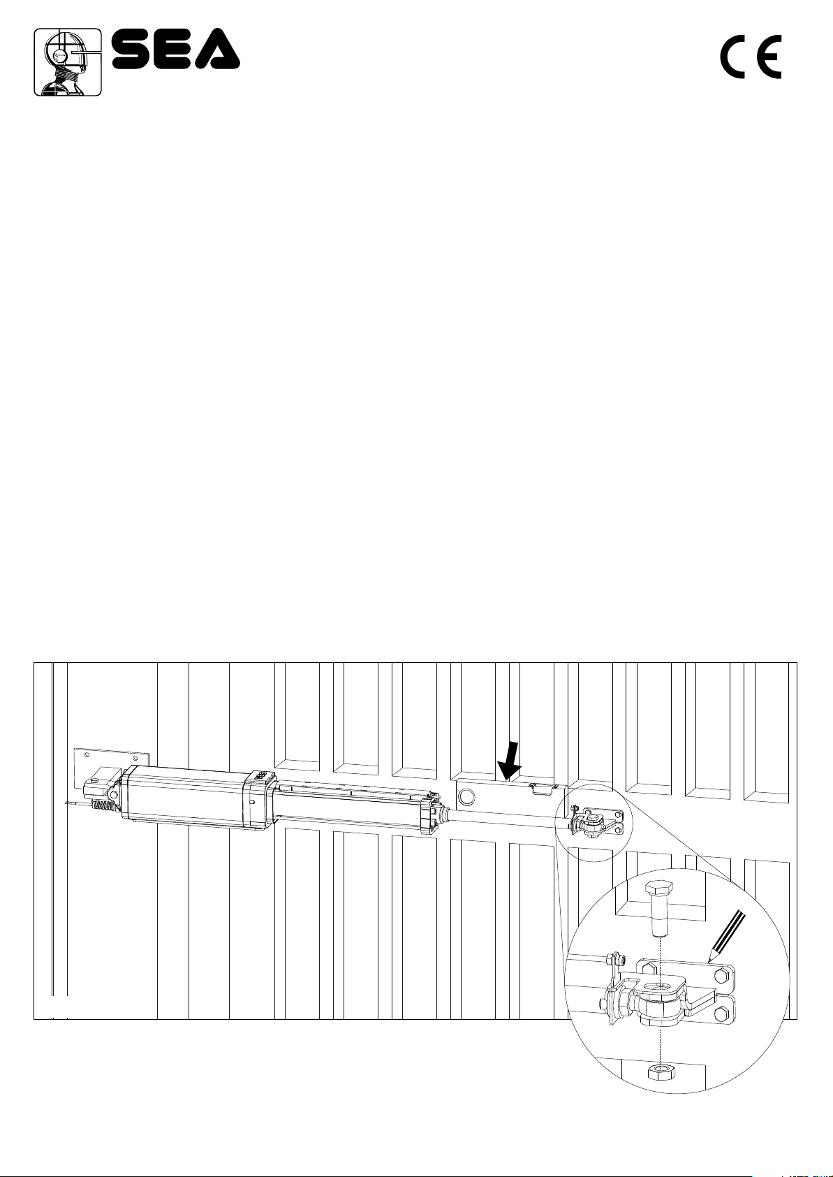
Fig. 3
Fig. 4
POSIZIONAMENTO DELL’ATTACCOANTERIORE
Una volta fissato l’operatore sull’attacco posteriore portare l’anta del cancello in posizione di chiusura ed eseguire le seguenti operazioni:
1) Sbloccare l’operatore.
2)Tirare fuori completamente lo Stelo cromato, poi riportarlo indietro di minimo 1 cm
3) Fissare lo stelo sul attacco anteriore (Fig. 4).
4) Posizionare l’operatore in modo che risulti perfettamente orizzontale e quindi segnare la posizione dell’attacco anteriore (Fig.3).
Attenzione: evitare di saldare l’attacco anteriore con lo stelo dell’operatore oleodinamico già fissato; i residui (schizzi) di saldatura potrebbero
compromettere la cromatura dello stelo.
POSITIONING OF THE FRONT FIXATION
Once the operator has been mounted on the back fixation close the leaf and do as follows:
1) Release the operator.
2) Pull out completely the chromium plated rod, afterwards bring it back about 1 cm
3) Fix the rod on the front fixation (Fig. 4).
4) Position the operator perfectly horizontal and mark the position of the front fixation (Fig.3).
Attention: Avoid the welding of the front fixation to the rod of the hydraulic operator already fixed as the welding residual (squirt) could ruin the
chromium -plating of the rod.
POSITIONNEMENTATTAQUEANTERIEUR
Après avoir fixé l’opérateur sur l’attaque postérieur fermer le vantail et exécuter le suivantes opérations:
1) Déverrouiller l’opérateur.
2)Sortir complètement la tige chromée, après la rentrer d’au moins 1 cm.
3) Fixer la tige sur l’attaque antérieur (Fig. 4).
4) Positionner l’opérateur de façon parfaitement horizontal donc marquer la position de l’attaque antérieur (Fig. 3).
Attention: éviter de souder l’attaque antérieur avec la tige de l’opérateur hydraulique déjà fixée: Les déchets de soudure pourraient
compromettre le chromage de la tige.
POSICIONAMIENTO DEL ENGANCHE ANTERIOR
Una vez fijado el operador en el enganche posterior llevar el anta de la cancela en posicion de cierre y efectuar las siguientes operaciones:
1) Desbloquear el operador.
2) Jalar hacia fuera completamente la varilla cromada,de minimo 1 cm.
3) Fijar la varilla en el enganche anterior (Fig. 4).
4) Posicionar el operador en modo que resulte prefectamnete horizontal y por tanto señalar la posicion del enganche anterior (Fig. 3).
Atencion: evitar de soldar el enganche anterior con la varilla del operador oleodinamico ya fijado; los residuos (salpicaduras) de soldadura
podria comprometer la cromadura de la carrera.
Sistemi Elettronici
di Apertura Porte e Cancelli
International registered trademark n. 804888
®
67411840 3Rev.01 - 06/2015

MONTAGGIO SNODO SFERICO e PIASTRINA
Montare lo snodo sferico come mostrato in Fig.5.
Montare la piastrina come mostrato in Fig.6.
BALL JOINT and PLATELET MOUNTING
Mount the ball joint as shown in Fig.5.
Mount the platelet as shown in Fig.6.
MONTAGGIO ENCODER - ENCODER INSTALLATION
INSTALLATION ENCODEUR - MONTAJE ENCODER
Fig. 5 Fig. 6
Sistemi Elettronici
di Apertura Porte e Cancelli
International registered trademark n. 804888
®
MONTAGE JONCTION SPHERIQUE ET PLAQUE
Monter le jonction sphérique comme montré en Fig.5.
Monter la plaque comme montré en Fig.6.
MONTAJE ARTICULACION ESFERICAY PLAQUITA
Montar la articulación esférica como Fig.5.
Montar la plaquita como Fig.6.
HALT TANK 270/390 HALT TANK 270/390
674118404 Rev.01 - 06/2015
ATTENZIONE: Durante la fase di montaggio dei dadi del tirante, fare attenzione a non far ruotare il tirante dell’Encoder perché potrebbe
arrecare malfunzionamenti all’Encoder stesso.
WARNING: During the assembly of the tie rod nuts, be careful not to rotate the rod of the Encoder because it could cause malfunctions to
the Encoder itself.
AVERTISSEMENT: Lors de l'assemblage des écrous de tirants, veillez à ne pas faire tourner la tige de l’encodeur, car elle pourrait
provoquer des dysfonctionnements à l’encodeur lui-même.
ADVERTENCIA: Durante el montaje de las tuercas del tirante, atención que el tirante del encoder no ruede, ya que podría causar fallos de
funcionamiento en el Encoder.
Fig. 7 Mini Tank Half Tank 270-390
REGOLAZIONE SNODO SFERICO
Regolare lo snodo sferico come mostrato in Fig.8 e Fig.9.
BALL JOINT ADJUSTMENT
Adjust the ball joint as shown in Fig.8 and Fig.9.
MONTAGGIO SINISTRO
LEFT ASSEMBLY
MONTAGE GAUCHE
MONTAJE IZQUIERDO
MONTAGGIO DESTRO
RIGHT ASSEMBLY
MONTAGE DROITE
MONTAJE DERECHO
5 mm Max
Fig. 8 Fig. 9
5 mm Max
Sistemi Elettronici
di Apertura Porte e Cancelli
International registered trademark n. 804888
®
MONTAGGIO SINISTRO
LEFT ASSEMBLY
MONTAGE GAUCHE
MONTAJE IZQUIERDO
MONTAGGIO DESTRO
RIGHT ASSEMBLY
MONTAGE DROITE
MONTAJE DERECHO
Fig. 10 Fig. 11
HALT TANK 270/390 HALT TANK 270/390
MINI TANK MINI TANK
67411840 5
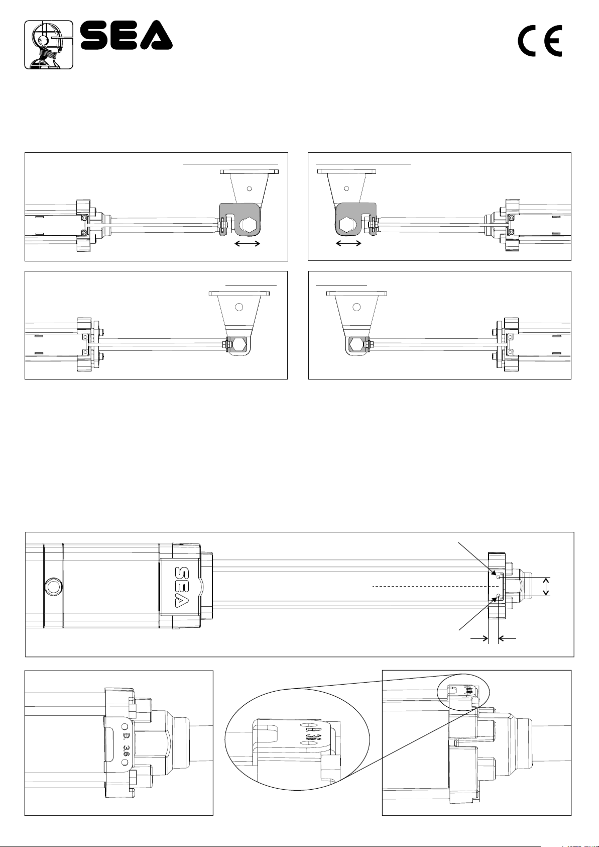
Ø 3,6 mm
Ø 3,6 mm
10,5 mm
20
mm
=
=
Per poter installare l’Encoder su impianti già esistenti (da matr. num. COW104261625 per l’HalfTank, da matr. num. A0S104304856 per il Mini
Tank) è necessario effettuare i due fori come evidenziato in Fig.12, sostituendo la centrale di comando. Usare la maschera di foratura per
effettuare i prefori come in fig.12a-12b.
Fig. 12
In order to install the Encoder on already existing installations (starting from serial number COW104261625 for Half Tank and from serial
number A0S104304856 for Mini Tank) it is necessary to make the two holes as shown in Fig.12, replacing the control unit.
Use the hole drilling template to make the pre-holes as in fig.12a-12b.
Pour installer l'Encodeur sur des installations déjà existantes (à partir du numéro de série COW104261625 pour Half Tank et à partir du numéro
de série A0S104304856 pour Mini Tank) il est nécessaire de faire les deux trous comme montré dans la Fig.12, en remplacement l’armoire de
commande. Utilisez le gabarit de perçage pour faire les pré-trous comme dans Fig.12a-12b.
Para poder instalar el Encoder sobre instaciones ya existentes, de matr. num. para el Half Tank, de matr. num.
para los Minos Tank), es necesario efectuar los dos agujeros como evidenciado en Fig.12, reemplazando la central de
mando.
COW104261625
A0S104304856
Utilizar la mascarilla de horadación para hacer los pre-agujeros como en la imagen 12a-12b,
AJUSTEMENT DE LA JONCTION SPHERIQUE
Ajuster la jonction sphérique comme illustré à la figure 8 et la figure 9.
REGULACION ARTICULACION ESFERICA
Regular la articulación esférica como Fig.8 y Fig.9.
Fig. 12a
Rev.01 - 06/2015
Fig. 12b
Other manuals for MINI TANK
1
This manual suits for next models
2
Popular Media Converter manuals by other brands


H&B
H&B TX-100 Installation and instruction manual

Bolin Technology
Bolin Technology D Series user manual

IFM Electronic
IFM Electronic Efector 400 RN30 Series Device manual

GRASS VALLEY
GRASS VALLEY KUDOSPRO ULC2000 user manual

Linear Technology
Linear Technology DC1523A Demo Manual

Lika
Lika ROTAPULS I28 Series quick start guide

Weidmuller
Weidmuller IE-MC-VL Series Hardware installation guide

Optical Systems Design
Optical Systems Design OSD2139 Series Operator's manual

Tema Telecomunicazioni
Tema Telecomunicazioni AD615/S product manual

KTI Networks
KTI Networks KGC-352 Series installation guide

Gira
Gira 0588 Series operating instructions

Lika
Lika SFA-5000-FD user guide