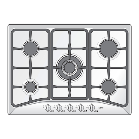
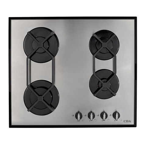
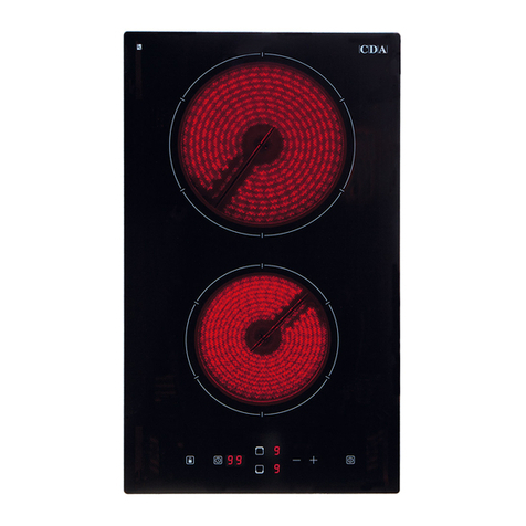
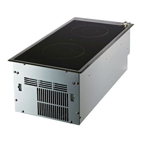
CDA HG3610BL Service manual

www.cda.eu
HG3610BL
HG3620BL
Built- in gas on glass
Cooking Hobs
Installation, Use and Maintenance
GB

2
DECLARATION OF CE CONFORMITY
• This appliance has been designed to be used only for cooking. Any other use (such as heating
a room) is improper and dangerous.
• This appliance has been designed, constructed, and marketed in compliance with:
-Safety requirements of the“Gas”Regulation (EU) 2016/426;
-Safety requirements of the“Low voltage” Directive 2014/35/EU;
-Safety requirements of the“EMC” Directive 2014/30/EU;
-Requirements of EU Directive 93/68/EEC;
-Requirements of EU Directive 2011/65/EU. GB
Important
This appliance is designed and manufactured solely for the cooking of domestic (household)
food and is not suitable for any non domestic application and therefore should not be used in a
commercial environment.
The appliance guarantee will be void if the appliance is used within a non domestic environment
i.e. a semi commercial, commercial or communal environment.
The CDA Group Ltd cannot be held responsible for injuries or losses caused by incorrect use or
installation of this product. Please note that CDA reserve the right to invalidate the guarantee
supplied with this product following incorrect installation or misuse of the appliance.
Appliance Information:
Please enter the details on the appliance rating plate below for reference, to assist CDA Customer
Care in the event of a fault with your appliance and to register your appliance for guarantee
purposes.
Appliance Model
Serial Number
Important Information for Correct Disposal of the Product in Accordance with
EC Directive 2012/19/EC.
At the end of its working life, the product must not be disposed of as urban
waste. It must be taken to a special local authority dierentiated waste
collection centre or to a dealer providing this service.
Disposing of a household appliance separately avoids possible negative
consequences for the environment and health deriving from inappropriate
disposal and enables the constituent materials to be recovered to obtain
signicant savings in energy and resources. As a reminder of the need to
dispose of household appliances separately, the product is marked with a
crossed-out wheeled dustbin.

3
IMPORTANT SAFETY PRECAUTIONS AND RECOMMENDATIONS
IMPORTANT: This appliance is designed and manufactured
solely for the cooking of domestic (household) food and is
not suitable for any non domestic application and therefore
should not be used in a commercial environment.
The appliance guarantee will be void if the appliance is used
within a non domestic environment i.e. a semi commercial,
commercial or communal environment.
Read the instructions carefully before installing and using
the appliance.
• This appliance has been designed and manufactured in compliance
with the applicable standards for the household cooking products and
it fullls all the safety requirements shown in this manual, including
those for surface temperatures.
Some people with sensitive skin may have a more pronounced
temperature perception with some components although these parts
are within the limits allowed by the norms.
The complete safety of the appliance also depends on the correct use,
we therefore recommend to always pay a extreme attention while
using the product, especially in the presence of children.
• After having unpacked the appliance, check to ensure that it is not
damaged.
In case of doubt, do not use it and consult your supplier or a
professionally qualied technician.
• Packing elements (i.e. plastic bags, polystyrene foam, nails, packing
straps, etc.) should not be left around within easy reach of children, as
these may cause serious injuries.
• Some appliances are supplied with a protective lm on steel and
aluminium parts.This lm must be removed before using the appliance.
• IMPORTANT: The use of suitable protective clothing/gloves is
recommended when handling or cleaning this appliance.
• Do not attempt to modify the technical characteristics of the appliance
as this may become dangerous to use. The manufacturer declines all
responsibility for any inconvenience resulting from the inobservance
of this condition.

4
• CAUTION: this appIiance must only be installed in a permanently
ventilated room in compliance with the applicable regulations.
• Do not carry out cleaning or maintenance operations on the appliance
without having previously disconnected it from the electric power
supply.
• Do not use a steam cleaner because the moisture can get into the
appliance therefore making it unsafe.
• Do not cover the hob with aluminium foils.
• Do not touch the appliance with wet or damp hands (or feet).
• Do not use the appliance whilst in bare feet.
• If you should decide not to use this appliance any longer (or decide to
substitute another model), before disposing of it, it is recommended
that it be made inoperative in an appropriate manner in accordance to
health and environmental protection regulations, ensuring in particular
that all potentially hazardous parts be made harmless, especially in
relation to children who could play with unused appliances.
• The various components of the appliance are recyclable. Dispose of
them in accordance with the regulations in force in your country. If the
appliance is to be scrapped, remove the power cord.
• After use, ensure that the knobs are in the o position.
• Children less than 8 years of age shall be kept away unless continuously
supervised.
• This appliance can be used by children aged from 8 years and above
and persons with reduced physical, sensory or mental capabilities or
lack of experience and knowledge if they have been given supervision
or instruction concerning use of the appliance in a safe way and
understand the hazards involved. Children shall not play with the
appliance. Cleaning and user maintenance shall not be made by
children without supervision.
• The manufacturer declines all liability for injury to persons or damage
to property caused by incorrect or improper use of the appliance.
• WARNING: During use the appliance and its accessible parts become
hot; they remain hot for some time after use.
–Care should be taken to avoid touching heating elements on the
hob.
–To avoid burns and scalds, young children should be kept away.
• Make sure that electrical cables connecting other appliances in the
proximity of the cooktop cannot come into contact with the hob.

5
• WARNING: Unattended cooking on a hob with fat or oil can be
dangerous and may result in re. NEVER try to extinguish a re with
water, but switch o the appliance and then cover ame e.g. with a lid
or a re blanket.
• WARNING: Danger of re: do not store items on the cooking surfaces.
• Do not place or leave empty pans on the glass ceramic hob.
• Do not allow heavy or sharp objects to drop on the glass ceramic hob.
• Do not scratch the hob with sharp objects. Don’t use the hob as a work
surface.
• WARNING: If the hob is cracked or otherwise damaged by falling
objects etc., disconnect the appliance from the electrical power supply
to avoid the possibility of electric shock and call Customer Service.
• WARNING: When correctly installed, your product meets all safety
requirements laid down for this type of product category. However
special care should be taken around the underneath of the appliance
as this area is not designed or intended to be touched and may contain
sharp or rough edges, that may cause injury.
• CAUTION: The cooking process has to be supervised. A short term
cooking process has to be supervised continuously.
• If the power supply cable is damaged, it must be replaced only by an
authorized service agent in order to avoid a hazard.
• If the appliance is not tted with a supply cord and a plug, or with
other means for disconnection from the supply mains having a
contact separation in all poles that provide full disconnection under
overvoltage category III conditions, means for disconnection must be
incorporated in the xed wiring in accordance with the wiring rules.
• WARNING: The appliance and its accessible parts become hot during
use.
Care should be taken to avoid touching heating elements.
Children less than 8 years of age shall be kept away unless continuously
supervised.
• WARNING: Use only hob guards designed by the manufacturer of the
cooking appliance or indicated by the manufacturer of the appliance
in the instructions for use as suitable or hob guards incorporated in
the appliance. The use of inappropriate guards can cause accidents.

6
ENERGY LABELLING/ECODESIGN
• Commission regulation (EU) No 66/2014 (implementing Directive 2009/125/EC of the
European Parliament and of the Council).
Reference to the measurement and calculation methods used to establish compliance with the
above requirements:
• Standard EN30-2-1 (hobs: gas red burners).
USE OF THE APPLIANCE, ENERGY SAVING TIPS
HOB
GAS FIRED BURNERS
• It is important that the diameter of the pot be suitable to the size of the burner so as not to
compromise the high output of the burners and therefore energy waste. A small pot on a
large burner does not give you a boiling point in a shorter amount of time since the capacity
of heat absorption of a liquid mass depends on the volume and the surface of the pot.
• Avoid keeping a burner on without something on it (without pot).

7
ADVICEADVICE
for thefor the
INSTALLERINSTALLER

8
IMPORTANT :
• The appliance is designed and approved for domestic use only and should not be installed in
a commercial, semi commercial or communal environment.
Your product will not be guaranteed if installed in any of the above environments and
could aect any third party or public liability insurances you may have.
The appliance may be installed in a kitchen, kitchen/diner or a bed sitting room, but not in
a room or space containing a bath or a shower without rst consulting current regulations.
The appliance must not be installed in a bed-sitting room of less than 20 m3.
• This appliance is to be installed, regulated and adapted to function only by an authorized person
in compliance with the current local regulations in force and in observation of the instructions
supplied by the manufacturer.
Failure to comply with this condition will render the guarantee invalid.
The appliance installation must only be carried out by a
SUITABLY QUALIFIED AND
REGISTERED TECHNICIAN
and in compliance with local safety standards.
Failure to observe this rule will invalidate the warranty.
• The appliance must be installed in compliance with regulations in force in your country and
in observation of the manufacturer’s instructions.
• Installation technicians must comply to current laws in force concerning ventilation and the
evacuation of exhaust gases.
• Incorrect installation, for which the manufacturer accepts no responsibility, may cause personal
injury or damage.
• This appliance shall only be serviced by authorized personnel.
• Always disconnect the appliance from mains power supply before carrying out any maintenance
operations or repairs.
• Important: The use of suitable protective clothing/gloves is recommended when
handling or cleaning of this appliance.
• These tops are designed to be embedded into kitchen xtures measuring 600 mm in
depth, working surface 30 to 40 mm thick.
• The appliance must be housed in heat-resistant units.
• The walls of the units must not be higher than work top and must be capable of resisting
temperatures of 105°C above room temperature.
• We would point out that the adhesive which bonds the plastic laminate to the furniture
must withstand temperatures not less than 150°C to avoid delamination.
• Do not install the appliance near inammable materials (eg. curtains).
WARNING!
When correctly installed, your product meets all safety requirements laid down for this type
of product category. However special care should be taken around the underneath of the
appliance as this area is not designed or intended to be touched and may contain sharp or
rough edges, that may cause injury.

9
Installation
TECHNICAL INFORMATION FOR THE INSTALLER
In order to install the cooker top into the kitchen xture, a hole with the dimensions shown in g.
1
has to be made, bearing in mind the following:
• A 40mm ventilation gap must be provided between the bottom of the appliance and any
cabinetry, draw unit or appliance.
• If the base of the cooktop is accessible through a cupboard or drawer space after installation,
a thermal protection barrier is not required.
• If the cooktop is installed above an oven, the two appliances shall be connected to the gas
and/or electrical supply with independent connections.
• The cooker top must be kept no less than 200 mm away from any side wall (from side edge
of cutout - gs. 1, 2).
• The hob must be installed at least 60 mm from the wall (from rear edge of cutout - g. 1).
• There must be a distance of at least 650 mm between the hob and any wall cupboard or
extractor hood positioned immediately above (see g. 2).

10
X(1) X=8 mm
(2) X=4 mm
Measures (mm)
Description A B C D E F
(minimum) G
(minimum)
30cm wide models 300 510
or
520
50 (1)
54 (2)270 480 60 200
650 mm
450 mm
min 200mm
500 mm
E
F
D
G
B
A
C
Fig. 1
Fig. 2
Cooktop
installed

11
FASTENING THE COOKTOP
Each cooktop is provided with an installation kit including brackets and screws for fastening the
cooktop to benches from 30 to 40mm thick.
The kit includes two “F” type brackets (for the front of the cooktop), two “R” type brackets (for the
rear of the cooktop) and four self-threading screws“S”.
• Cut the unit according to the dimensions in g. 1.
• Stretch gasket “G” over the edge of the hole made, being careful to overlay the junction
edges (fig. 4).
• Fasten the brackets “F” and “R” to the appropriate socket holes (g. 3), without tightening the
screws “S” for the moment. Make sure that the tabs are mounted correctly, as shown (gs. 5,
6). Rotate the tabs so that the cooktop can be put into the cutout.
• Put the cooktop into the cutout and position it correctly.
• Put the brackets “F” and “R” into place; tooth “A” of the brackets should go into the hole (gs.
5, 6).
• Tighten screws “S” until the cooktop is completely secured to the bench.
• Using a sharp cutter or trimmer knife, trim the excess sealing material around the edge of the
cooktop.
Take care not to damage the workbench.
30 mm min.
40 mm max.
S
A
F
G (G2)
30 mm min.
40 mm max.
40 mm min.
40 mm min.
S
A
R
G (G1)
30 mm min.
40 mm max.
S
A
F
G (G2)
30 mm min.
40 mm max.
40 mm min.
40 mm min.
S
A
R
G (G1)
Fig. 5 Fig. 6
Fig. 3
Rear Fixing Brackets Front Fixing Brackets
G
Fig. 4
F
F
RR

12
PROVISION FOR VENTILATION
• The appliance should be installed into a room or space with an air supply in accordance with
the current version of BS 5440-2: 2000.
• For rooms with a volume of less than 5m3- permanent ventilation of 100 cm2free area must
be provided.
• For rooms with a volume of between 5 m
3
and 10 m
3
a permanent ventilation of 50 cm
2
free area
will be required unless the room has a door which opens directly to the outside air in which case
no permanent ventilation is required.
• For rooms with a volume greater than 10 m3- no permanent ventilation is required.
Note: Regardless of room size, all rooms containing the appliance must have direct access to
the outside air via an openable window or equivalent.
• Where there are other fuel burning appliances in the same room, the current version of
BS
5440-2: 2000 should be consulted to determine the correct amount of free area ventilation
requirements.

13
VENTILATION REQUIREMENTS
The appliance must be installed in compliance with applicable local regulations concerning
ventilation and the evacuation of exhaust gases.
Intensive and prolonged use may require extra ventilation, e.g. opening a window, or more
ecient ventilation increasing the mechanical suction power if this is tted.
CHOOSING SUITABLE SURROUNDINGS
The room where the gas appliance is to be installed must have a natural ow of air so that the gas
can burn (in compliance with applicable local regulations).
The ow of air must come directly from one or more openings made in the outside walls with a free
area of at least 100 cm2(or refer to applicable local regulations).
The openings should be near the oor and preferably on the side opposite the exhaust for
combustion products and must be made so that they cannot be blocked from either the inside
or the outside.
When these openings cannot be made, the necessary air can come from an adjacent room which
is ventilated as required, as long as it is not a bed room or a danger area (in compliance with
applicable local regulations).
In this case, the kitchen door must allow the passage of the air.
DISCHARGING PRODUCTS OF COMBUSTION
Extractor hoods connected directly to the outside must be provided, to allow the products of
combustion of the gas appliance to be discharged (g. 7).
If this is not possible, an electric fan may be used, attached to the external wall or the window;
the fan should have a capacity to circulate air at an hourly rate of 3-5 times the total volume of the
kitchen (g. 8).
The fan can only be installed if the room has suitable vents to allow air to enter, as described under
the heading “Choosing suitable surroundings”.
H min 650 mm
Extractor hood
for products of
combustion
Air vent Air vent
Electric fan to
extract products of
combustion
Fig. 8
Fig. 7

14
GAS INSTALLATION REQUIREMENTS
Important !
• Before installation, make sure that the local distribution conditions (gas
type and pressure) and the adjustment of this appliance are compatible. The
appliance adjustment conditions are given on the plate or the label.
• This appliance must be installed and serviced only by a suitably qualied,
registered installer with technical knowledge of both gas installation and
electricity. The installation or service must comply with the current editions of
the applicable standards, regulations, and codes of practice governing gas and
electrical installations.
• Failure to install the appliance correctly could invalidate any manufacturer’s
warranty.
This appliance is supplied for use on NATURAL GAS or LPG (check the gas regulation label attached
on the appliance).
• Appliances supplied for use on NATURAL GAS: they are adjusted for this gas only and cannot
be used on any other gas (LPG) without modication. The appliances are manufactured for
conversion to LPG.
• Appliances supplied for use on LPG: they are adjusted for this gas only and cannot be used
on any other gas (NATURAL GAS) without modication. The appliances are manufactured for
conversion to NATURAL GAS.
If the NATURAL GAS/LPG conversion kit is not supplied with the appliance this kit can be purchased
by contacting the After-Sales Service.
INSTALLATION & SERVICE REGULATIONS
It is a legal requirement that all gas appliances are Installed & Serviced by a competent person in
accordance with the current editions of the following Standards & Regulations or those regulations
appropriate to the geographical region in which they are to be installed:
• Gas Safety (Installation & Use) Regulations
• Building Regulations
• British/European Standards
• Regulations for Electrical Installation
Installation and service of any gas product must be made by a suitably qualied and registered
person competent on the type of product being installed or serviced and holding a valid certicate
of competence for the work being carried out. Currently the proof of competence is the Accredited
Certication Scheme (ACS) or N/SVQ that has been aligned to the ACS.
It is also a requirement that all businesses or self employed installers are members of a class of
person approved by the Health and Safety Executive.
Failure to install the appliance correctly could invalidate any manufacturers warranty and lead to
prosecution under the above quoted regulations.
Gas Section

15
GAS CONNECTION
GB Cat: II 2H 3+
Installation to Natural Gas
Installation to Natural Gas must conform to the Code of Practice, etc.
The supply pressure for Natural Gas is 20 mbar.
The installation must conform to the relevant British/European Standards.
Installation to LP Gas
When operating on Butane gas a supply pressure of 28-30 mbar is required.
When using Propane gas a supply pressure of 37 mbar is required.
The installation must conform to the relevant British/European Standards.
Warning: Only a suitably qualied and registered installer, also with technical knowledge of
electricity should install the appliance.
He should observe the Regulations and Codes of Practice governing such installation of gas
appliances.
Note: It is recommended that the gas connection to the appliance is installed with a exible hose
connecting tube made to BS669 or EN 14800.
Notes:
• Flexible hoses can be used where the sited ambient temperature of the hose does not
exceed 70°C. These hoses must be manufactured in accordance with BS669 part 1 or EN
14800 and be of the correct construction for the type of gas being used.
• Gas hoses designed for natural gas MUST NOT be used for supplying LPG gas (LPG gas
hoses can be identied by a either a red band or stripe on the rubber outer coating of
the hose).
The hose should not be crushed or trapped or be in contact with sharp or abrasive
edges.
IMPORTANT! It is the responsibility of the gas installer to ensure that the product is fully
tested and commisioned in accordance with current regulations to ensure there are no gas
escapes.

16
The tting (g. 9) is made up of:
–1 nut “A”
–1 elbow tting “C”
–gasket “F”
Connection to the Gas Supply
–Be careful when exible pipes are used that
they do not come into contact with moving
parts.
–To maintain the thickness of 3 cm, the
hob is tted with a channel to contain the
connection pipe.
–The gas inlet union can be turned in the
direction required after the elbow tting“C”
and nut “A” connection (gure 9) has been
slackened (g. 10).
–Never put it in the horizontal or vertical
position.
–Never attempt to turn the elbow “C” without
having rst slackened o the relative lock nut
“A”.
–The gasket “F” (g. 9) guarantees the seal of
the gas connection. It is recommended that
it be replaced whenever it shows even the
slightest deformation or imperfection.
If installation is to be carried out using a exible
connector (to BS669 or EN14800), then the
following points must be adhered to:
Note: The gas installation pipes and the nal
connection to the appliance connecting pipe
shall be of a sucient size to maintain the heat
output of the appliance as specied on the rating plate.
1. The appliance exible connector should not be subject to undue forces, either in normal use
whilst being connected or disconnected.
2. The appliance exible connector should not be subject to excessive heat by direct exposure
to ue products or by contact with hot surfaces.
3. The socket into which the plug of the appliance exible connector ts should be permanently
attached to a rmly xed gas installation pipe and positioned such that the hose hangs freely
downwards in a natural loop and does not touch the oor.
4. The appliance exible connector should be positioned such that it will not suer mechanical
damage; eg abrasion from the surrounding kitchen furniture which may be moved in use,
such as a door or drawer, or by being trapped by a stability device.
5. The bayonet tting should be accessible for disconnection after moving the appliance.
1/2" BSPT (R) conical/taper
(ISO 7-1) male
1/2" BSPP (G) parallel
(ISO 228-1) male
1/2" BSPP (G) parallel
(ISO 228-1) female
C F A
Fig. 9
Fig. 10

17
LUBRICATION OF THE GAS TAPS
In case of diculty in the gas taps operation, call Service.
IMPORTANT
All intervention regarding installation, maintenance and conversion of the appliance must
be fullled with original factory parts.
The manufacturer declines any liability resulting from the non-compliance of this obligation.
TABLE FOR THE CHOICE OF THE INJECTORS
Cat: II 2H 3+ G30/G31
28-30/37 mbar
G20
20 mbar
BURNERS
Nominal
Power
[kW]
Reduced
Power
[kW]
Ø injector
[1/100 mm]
Ø injector
[1/100 mm]
Semi-rapid (SR) 1,75 0,45 66 101
Rapid (R) 3,00 0,75 87 129
Triple-ring (TR) 3,80 1,50 98 141
AIR VENT NECESSARY FOR GAS COMBUSTION = (2 m3/h x kW)
BURNERS Air necessary for combustion [m3/h]
Semi-rapid (SR) 3,50
Rapid (R) 6,00
Triple-ring (TR) 7,60
GAS MAINTENANCE
GB

18
J
Semi-rapid
and rapid
burner
REPLACEMENT OF THE INJECTORS
If the injectors are not supplied they can be
obtained from the “Service Centre”.
Select the injectors to be replaced according
to the “TABLE FOR THE CHOICE OF THE
INJECTORS”.
The nozzle diameters, expressed in
hundredths of a millimetre, are marked on the
body of each injector.
REPLACEMENT OF THE INJECTORS OF
THE COOKTOP BURNERS
To replace the injectors proceed as follows:
• Remove pan supports and burners from
the cooktop.
• Using a wrench, substitute the injectors
“J” (gs 11, 12) with those most suitable
for the kind of gas for which it is to be
used.
The burners are conceived in such a way
so as not to require the regulation of the
primary air.
Fig. 11
J
Fig. 12
Triple-ring burner

19
SETTING THE MINIMUM OF THE
COOKTOP BURNERS
In the minimum position the ame must have
a length of about 4 mm and must remain lit
even with a quick turn from the maximum
position to that of minimum.
The ame adjustment is done in the following
way:
• Turn on the burner.
• Turn the tap to the 'MINIMUM' position.
• Take o the knob.
• With a small at screwdriver turn the
screw “A” to the correct regulation (g.
13).
Normally for LPG tighten up the regulation
screw.
A
Fig. 13

20
Incorrect installation may be dangerous and the manufacturer can not be held responsible.
Warning! This appliance must be earthed The manufacturer declines all responsibility for
any problem caused by failure to observe this rule.
THIS APPLIANCE MUST BE CONNECTED TO THE MAINS SUPPLY BY A COMPETENT PERSON, USING
FIXED WIRING VIA A DOUBLE POLE SWITCHED FUSE SPUR OUTLET AND PROTECTED BY A 3A FUSE.
We recommend that the appliance is connected by a qualied electrician, who is a member of the
N.I.C.E.I.C. and who will comply with the I.E.E. and local regulations.
The wires in the mains lead of this appliance are coloured in accordance with the following code:
Green & Yellow = Earth, Blue = Neutral, Brown = Live.
As the colours of the wires in the mains lead for the appliance may not correspond with the
coloured markings identifying the terminals
connecting to the fuse spur, proceed as follows:
• The wire which is coloured green and yellow
must be connected to the terminal marked
E(Earth) or coloured green.
• The wire which is coloured blue must
be connected to the terminal marked N
(Neutral), or coloured black.
• The wire which is coloured brown must be
connected to the terminal marked L(Live),
or coloured red.
Note: Use a 3A Fuse
Assembly and electrical connection should be
carried out by specialised personnel.
When installing this product we recommend you
seek the help of another individual.
Mains Electricity Connection
FUSE
DOUBLE POLE SWITCHED
FUSED SPUR OUTLET
ON
USE A 3 AMP FUSE
Fig. 14
This manual suits for next models
1
Table of contents
Other CDA Hob manuals

CDA
CDA HCG602 Reference manual

CDA
CDA HC6621FR Specification sheet

CDA
CDA HG7251 User manual

CDA
CDA hc7620 Reference manual

CDA
CDA HCE550 Reference manual

CDA
CDA HVN61 Reference manual

CDA
CDA HC9606FR Specification sheet

CDA
CDA HCC762 Reference manual

CDA
CDA HVN 32 Series Instructions for use

CDA
CDA HN3615FR Quick start guide

CDA
CDA HG6001SS Quick start guide

CDA
CDA hc7620 Reference manual

CDA
CDA HG6250 Quick start guide

CDA
CDA CERAMIC HOBS HVC65 Reference manual

CDA
CDA HNG7410FR Quick start guide

CDA
CDA HCG302 Quick start guide

CDA
CDA hn3620 Reference manual

CDA
CDA HVG95 Reference manual

CDA
CDA hc9620 Reference manual

CDA
CDA HC6212FR Quick start guide