
365
UPO33
5<< >>6
2.3. Battery Handling
2.4. Installation, operation and maintenance handling
3. GENERAL DESCRIPTION
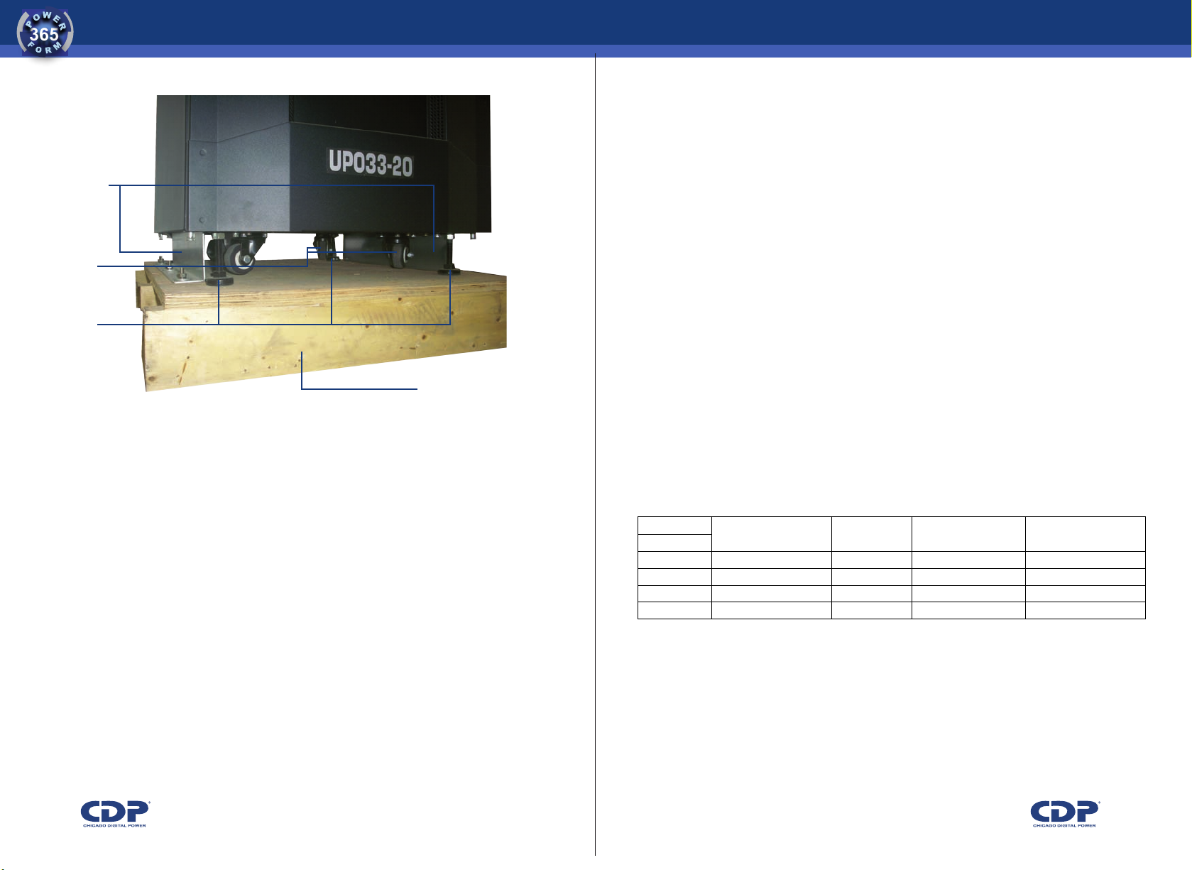
• When installing the UPS with flexible cables with a length sufficient to
enable the team to move in such a way that is accessible from all sides to
perform any service.
Batteries are elements with high energy storage capacity and generates
dangerous voltages within the UPS, even while disconnected from the power
supply unit of input, so both the team and their batteries should only be
operated by qualified personnel and take preventive measures listed below:
• Remove watches, rings and other metal objects.
• Use only tools with insulated handles.
• To change batteries, install the same amount and same type of batteries.
• Replace battery fuse only with same type and same rating.
• Do not open, or destroy, or burn batteries, the electrolyte may cause injury
to the skin and eyes. It is highly toxic. If exposed to fire may explode
• Disposal of batteries must be in accordance with relevant environmental
standards.
Here are some safety recommendations during installation, operation and
maintenance of the UPS:
• All work must be intervention at UPS Realize by qualified personnel.
• Prior to installation of the equipment must verify that all breakers are in the
OFF position, mainly batteries and must be handled only when the UPS is
completely interconnected to rush for strict compliance to the procedure
described in this manual.
• Remove the caps from the UPS and check that all internal components are
in perfect condition, while checking the fit of connectors
The UPO CDP Phase UPS provides AC power 33 to power equipment that
requires a good quality of energy such as computer equipment, communica-
tions, servers, data networks, electrical equipment (not recommended for
equipment used for life support) etc. automation systems.
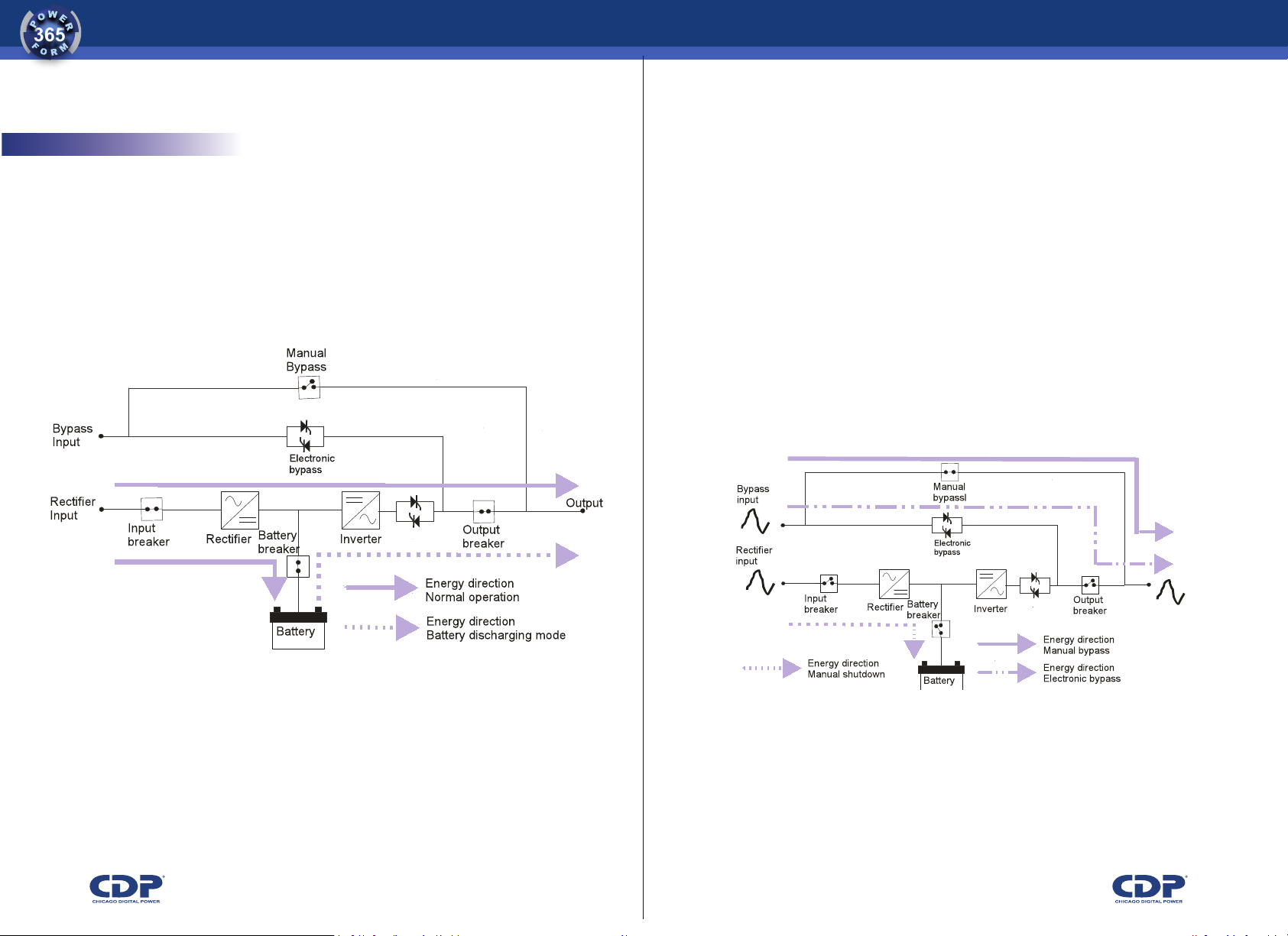
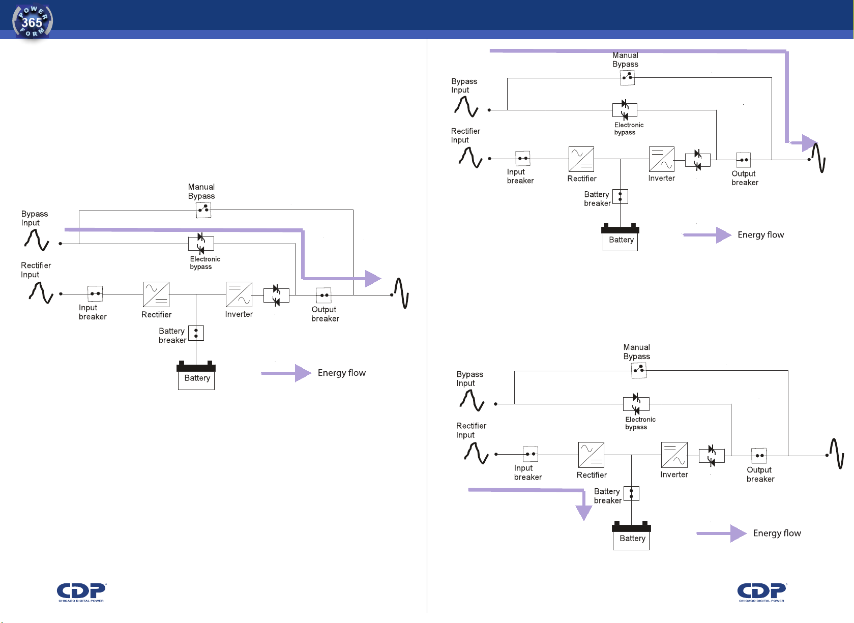
The PWM ON-LINE double conversion UPS provides free energy of the
main problems of the grid, such as blackouts, sudden changes in voltage
and / or frequency, power surges, brownouts, noise, transients, harmonic
distortion, etc.
The device has a user friendly interface, which displays the UPS status
easily. It also has an LCD screen through which you can consult various
UPS parameters such as voltages in each phase, frequency, temperature,
current, etc.
The device has an RS232 interface which allows system monitoring from a
PC. As optional devices can include an SNMP device or a cellular modem.
The latter two can monitor the UPS from a remote location via the Internet.
hWe recommend using a three-phase industrial breaker.
TABLE 4.2. CROSS SECTIONS OF THE WIRES TO THE OUTPUT OF THE UPS
hWe recommend using a three-phase industrial breaker.
?":"+GHEEBGFDHE+FBA2DEIJ9
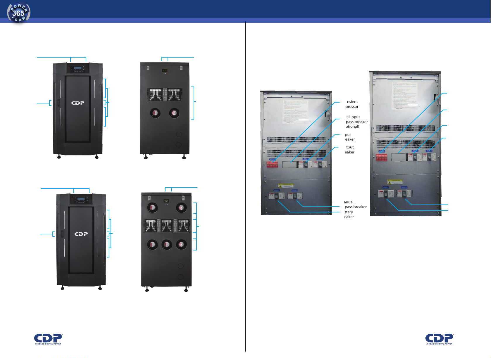
To access the terminals in the ups of 20 kva to 30 kva, remove the back cover. the terminals are at the
bottom. in the ups of 40 kva to 80 kva, the terminals are located on the front face. to access them you must
first open the front cover and then remove the cap covering the terminals (see figure 2.3), which is located
below the transient suppressor. figure 4.3 shows the connection terminals.
!
!
3;<D?J!H(6(!+B88JE>;B8!>J?C;8#:@!
P@)%F=BD<G:;
K"!"+G0%,-0'+/$%<'
GP 33 UPS includes a control panel that displays the status of the ups, and to see certain parameters on a
lcd screen (input voltage, output voltage, frequency, temperature, etc). figure 5.1 shows that interface.


 Plus Startup manual")


