CE CLEVELAND CE-2500-HVE User manual

CE-2500-HVE Band Sealer
Page 1
Contents
I. Use ...............................................................................................................................................2
II. Safety Precautions.......................................................................................................................................2
III. Main Specification.......................................................................................................................................3
IV. Performance Features .................................................................................................................................4
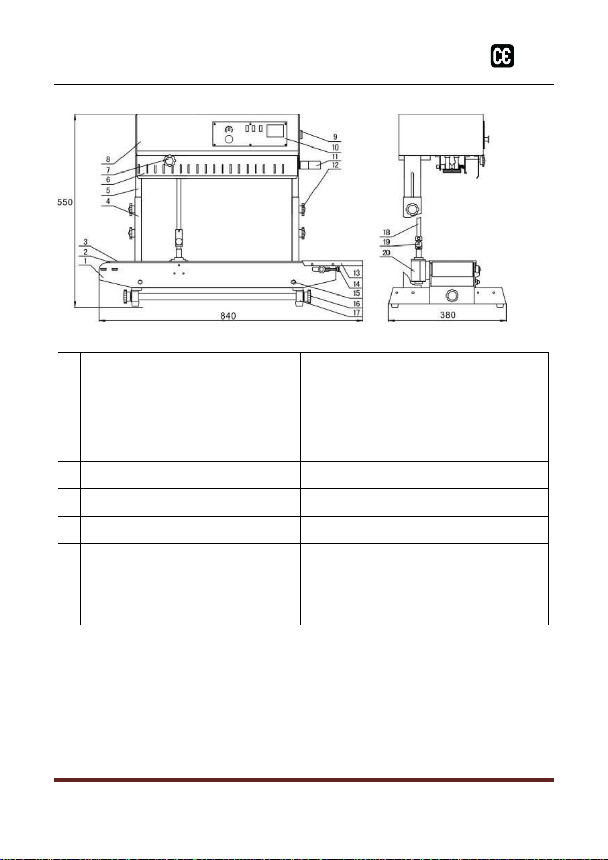
V. Structure & Working Principle .....................................................................................................................5
Diagram 5.1............................................................................................................................6
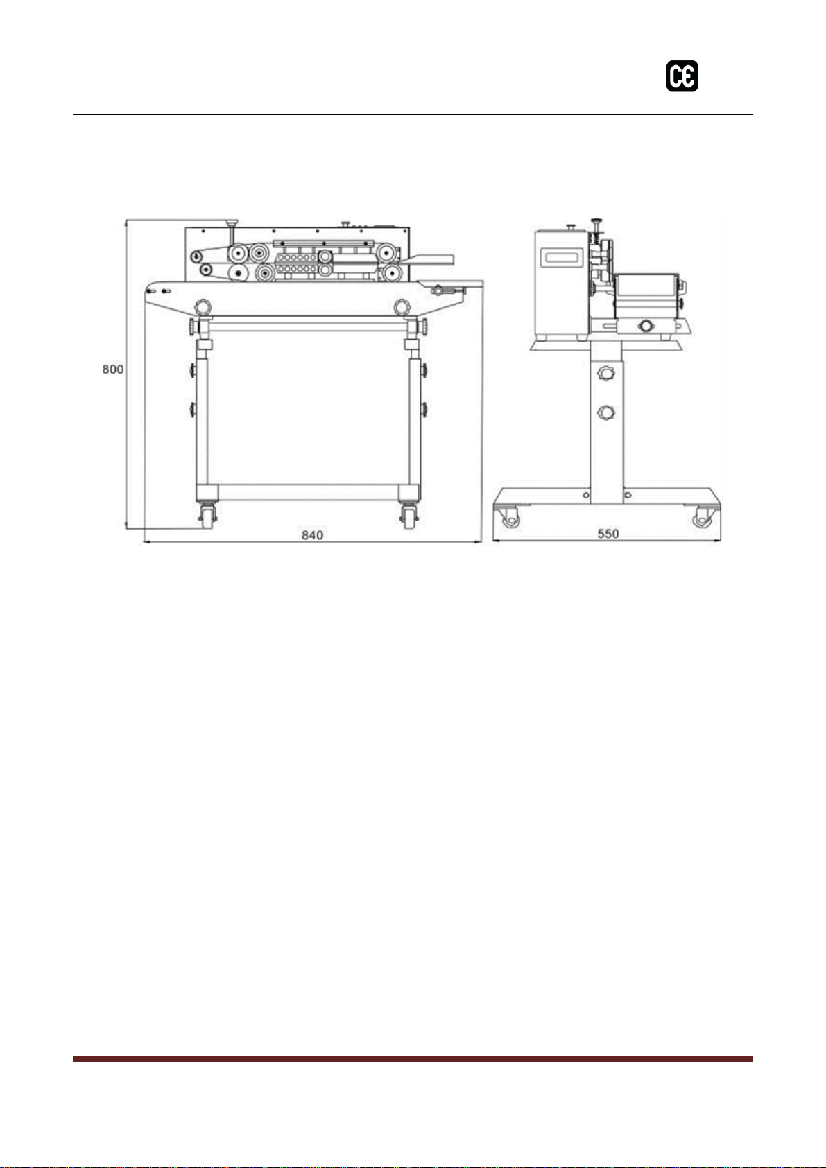
Diagram 5.2............................................................................................................................7
Diagram 5.3............................................................................................................................8
VI. Operational Use...........................................................................................................................................9
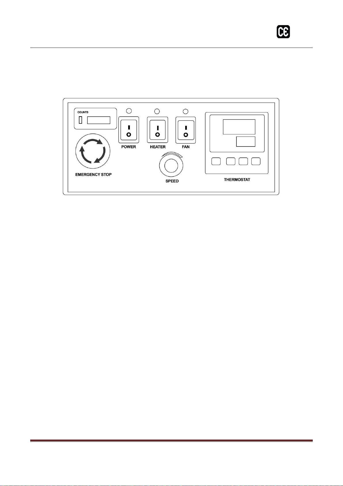
6.1. Control Panel ................................................................................................................................9
Diagram 6.1............................................................................................................................9
6.2. Prepare the machine for use ..........................................................................................................9
6.3. Sealing Belt Adjustment / Replacement .......................................................................................10
Diagram 6.2..........................................................................................................................10
6.4. Drive Wheel Block Adjustment.....................................................................................................11
Diagram 6.3..........................................................................................................................11
6.5. Conveyor Belt Adjustment / Replacement....................................................................................12
Diagram 6.4..........................................................................................................................12
6.6. Starting procedure .......................................................................................................................13
VII. CE-2500-HVE Horizontal to Vertical Guide .................................................................................................14
VIII. Stand Assembly .........................................................................................................................................17
IX. Electrical Diagram......................................................................................................................................20
Diagram 9.1..........................................................................................................................20
X. Sealing Unit Parts List ................................................................................................................................21
Diagram 10.1........................................................................................................................21
XI. Conveyer Parts List ....................................................................................................................................23
Diagram 11.1........................................................................................................................23
XII. Component Parts List.................................................................................................................................25
Diagram 12.1........................................................................................................................25
XIII. Conveyor Table Parts List ...........................................................................................................................27
Diagram 13.1........................................................................................................................27
XIV. CE-2500-HVE Parts Kit................................................................................................................................29
XV. Preventive Maintenance Checklist.............................................................................................................30
XVI. Troubleshooting.........................................................................................................................................31
XVII. Helpful Links .............................................................................................................................................32

CE-2500-HVE Band Sealer
Page 2
I. Use
This sealer is suitable for sealing all kinds of plastic films, which is widely used in fields of food,
medicine, chemicals, etc. It is the best sealing equipment for packing batch products from
factories and shops.
II. Safety Precautions
2.1. Make sure the adopted power supply is correct.
The machine adopts AC 110V. The yellow and green wire is the ground wire and cannot be
removed.
2.2. After the power is connected, do not touch any electrical parts.
2.3. .
2.4. When the machine is on, do not touch any moving parts.
2.5. When the machine is on, do not touch heating blocks or ink roller heating block.
2.6. Do not operate the machine in a corrosive environment.
2.7. Do not change any parts of the machine.
2.8. Keep the machine clean (both inside and outside), and clear of dirt from sealing belt.
2.9. Oil the gear and sprocket with semiliquid gear oil. Fill and exchange oil in worm-gear box
regularly.
2.10. Turn off the power when not use. Allow the machine to run long enough to cool down.
2.11. Keep this manual near the machine, for easy reference.

CE-2500-HVE Band Sealer
Page 3
III. Main Specification
Model
Items
Horizontal Mode
Vertical Mode
Voltage
AC 220V/50 110/60
Power
50W
Sealing Power
300×2(W)
Sealing Speed
0~12 (m/min)
Sealing Width
8 - 10(mm)
Temperature Controller
0~300(℃)( Stepless adjustable)
Height From Sealing Center To Conveyor
10~40 (mm)
150~270 (mm)
Film Thickness( Monolayer)
≤0.08 mm
Max. Single Conveyor Loading
≤1 Kg
Max. Overall Conveyor Loading
≤3 Kg
Dimension(LXWXH)
840×380×320(mm)
840×380×550(mm)
Net Weight
32 Kg
37 Kg

CE-2500-HVE Band Sealer
Page 4
IV.Performance Features
This sealer uses an electronic thermostat control unit and stepless speed-adjusting transmission
mechanism. It can seal various plastic film bags in different materials and can also be used with
varied packaging production lines. The machine has no limitations on sealing length with high
efficiency continuous sealing, reliable sealing quality, and convenient operation.
This series provides two models, including a horizontal and a vertical type. The horizontal type is
suited for packaging dry materials, while the vertical type is suited for packaging materials in
powder or liquid form.

CE-2500-HVE Band Sealer
Page 5
V. Structure & Working Principle
This machine is made up of the machine frame, speed regulator, sealing temperature control
system, transmission and conveyor system, and printing device (see Diagram).
The sealing and printing transmission are driven by one motor, which drives the sealing belts,
guiding belts and conveyor belt to work synchronously, as well as make printing mechanism working
intermittently.
5.1 Once the power is turned ON, the electrothermal elements start to produce heat, which
leads to a rapid temperature rise of both upper and lower heating blocks.
5.2 Adjust the temperature control and speed control to the required temperature and speed
for your application.
5.3 The plastic packing bag is transferred by the conveying belt, and its sealing part will be
guided into the clearance between two sealing belts,
5.4 The bag is clamped by two sealing belts and conveyed into the heating area.
5.5 Sealing belts are pressed by two heating blocks and impressing wheels which fuse the plastic
film together.
5.6 The sealed bag is conveyed into the cooling area for cooling.
5.7 The sealed bag is pressed by embossing wheel to make stripe or netted pattern.

CE-2500-HVE Band Sealer
Page 6
Diagram 5.1
1
101035
Guide Plate
9
101024
Driving Wheel
2
101035
Drive Wheel Adjusting Block
Upper
10
101018
Embossing Roller
2
101023
Drive Wheel Adjusting Block
Lower
11
101036
Silicone Wheel
3
101024
Driven Wheel
12
101014
Guiding Wheel
4
THC1
Control Panel
13
910701
Conveyor Belt
5
930305-U
930305-L
Heating Block
14
101333
Conveyor Table
6
102007
Holding Plate
15
930109-11
Fastening Knob for Elevating Table
7
102003
Pinch Roller
16
101334
Transverse Tightening Knob
for Conveyor Table
8
930306-U
930306-L
Cooling Block
17
101335
Ledge

CE-2500-HVE Band Sealer
Page 7
Diagram 5.2
1
101333
Conveyor Table
11
101035
Guide Plate
2
101012
Driving Roller
12
101341
Fastening Knob
3
910701
Conveyor Belt
13
101006
Worktable
4
101335
Fixed Bracket
14
930109-01
Adjusting Knob for Conveyor Belt
5
101336
Slip Bracket
15
930109-11
Tightening Nut
6
101337
Safety Cover
16
101334
Conveyor Table Transverse Tightening Knob
7
101338
Embossing Roller Adjusting Knob
17
101335
Rack
8
101339
Housing
18
101342
Vertical Shaft
9
QF1
Breaker
19
101343
Gimbal Assembly
10
101340
Control Panel
20
101344
Bevel Gear Assembly

CE-2500-HVE Band Sealer
Page 8
Diagram 5.3

CE-2500-HVE Band Sealer
Page 9
VI.Operational Use
6.1. Control Panel (See Diagram 6.1)
Diagram 6.1
6.2. Prepare the machine for use
6.2.1. This machine is equipped with a three-prong grounded socket. Be sure that the socket
is well connected for safe operation.
6.2.2. First-time use or too long intermission will make the heating elements damp. It is
necessary to preheat at lower temperature for several minutes before the normal
operation.
6.2.3. Adjust the height and position of the conveyor table to get the required sealing position
for your application.
6.2.4. Adjust the position of feed opening according to the external size from sealing line to
bag opening.
6.2.5. According to the thickness and material that to be sealed, adjust the clearance between
two heating blocks and two cooling blocks, so that both clearances are approximately
equal to the thickness of packing bag in one layer. This will guarantee sealing firmness
and high definition of embossing, and ensure a suitable length extended from the two
ends of seal.

CE-2500-HVE Band Sealer
Page 10
6.3. Sealing Belt Adjustment / Replacement
6.3.1. Remove the safety cover, after the heating blocks cool, turn stopping flakes on both upper
heating block and upper cooling block by 90° to lift both, then loosen the springs on both
embossing roller and pinch roller, meanwhile, remove the guiding belt, to prepare it for
removing sealing belts. (see Diagram 6.2)
6.3.2. Move the driven wheel seat (adjusting block) towards heating block and remove the
sealing belt.
6.3.3. Replace with a new sealing belt and install the guiding belt back.
6.3.4. Put the driven wheel, heating/cooling blocks, and pinch roller to the original position.
6.3.5. Connect to the power supply to test the machine. If irregular sealing appears on the belt,
make adjustment by adjusting screws on the driven wheel seat (adjusting block)( see
Diagram 6.3).
6.3.6. Install the safety cover. When the temperature reaches the set temperature, the machine
is ready.
Diagram 6.2
1
101347
Bolt
2
101348
Withdraw Stopping Flake
3
101345
Tightening Bolt
4
101345
Tightening Bolt
1
1
1
1
2
2
3
3
4
4

CE-2500-HVE Band Sealer
Page 11
6.4. Drive Wheel Block Adjustment
If the sealing belt is off tracking, adjust the screws on driven wheel seat (adjusting block), shown as
Diagram 6.4.
Diagram 6.3
1
101035
driven wheel seat adjusting plate - Upper
101023
driven wheel seat adjusting plate - Lower
2
101035
driven wheel seat adjusting block - Upper
101023
driven wheel seat adjusting block -Lower
3 / 4
101349
adjusting screw
5
9361112-117-60S
spring

CE-2500-HVE Band Sealer
Page 12
6.5. Conveyor Belt Adjustment / Replacement
When making adjustments to the conveyor table, loosen two nuts (1) at the bottom of the
conveyor table. There are three location holes on the housing (2), insert bolts in them as
needed, then fasten the nuts. Then move the conveyor table and equip the connecting shaft
(3) that would be in the spare parts into the universal joints. (see diagram 6.4).
Diagram 6.4
1
101334
Adjusting Knob
2
101335
Foot Rest

CE-2500-HVE Band Sealer
Page 13
6.6. Starting procedure
6.6.1. Connect to the power supply and press the Start switch, which will turn the indicator light
on. You can then adjust the speed controller knob to the desired speed. All transmission
parts start to run synchronously.
6.6.2. Fine tune the knob of embossing roller to make the wheel swivel and acheive the proper
pressure.
6.6.3. Turn Heat Seal switch ON, the green light of the electronic temperature controller will light
up. According to the material and thickness of the packing bag, adjust the temperature
controller to the necessary temperature. When the heating blocks begin to preheat, the
machine needs to be started and kept running at low speed.
6.6.4. According to the material and thickness that is being sealed, turn on the cooling fan if your
application requires.
6.6.5. Flatten and align the bag opening, then feed the bag by aligning the bag opening with the
guide plate. The bag opening is gripped by the sealing belts, which will make the bag move
forward automatically. At that momento, do not push it in or pull it out by force, otherwise
irregular sealing or breakdown will happen.
6.6.6. If it is found that there is dirt attached to the sealing belt or the heating block, stop the
sealer and clear it. Never clear the dirt with your hand when the temperature is high.
6.6.7. Stop operation
6.6.8. In order to prolong the service life of the sealer, before shutting down the machine, you
should return the temperature setting to “0” and turn on the fan. The temperature on the
indicator will begin to fall and the sealing belts should still be running. Once the temperature
drops below 100℃, can you turn off the fan and main power.
6.6.9. 6.6.8 Emergency stop switch:
6.6.10.At any time, the machine can be stopped immediately by pressing the emergency stop
switch. The emergency stop switch is a self-locking switch, and needs to rotate clockwise 120
degrees to open after self-lock.

CE-2500-HVE Band Sealer
Page 14
VII. CE-2500-HVE Horizontal to Vertical Guide
Step 1
Step 2
Step 3
Step 4
Step 5
Step 6

CE-2500-HVE Band Sealer
Page 15
Step 7
Step 8
Step 9
Step 10
Step 11
Step 12

CE-2500-HVE Band Sealer
Page 16
Step 13

CE-2500-HVE Band Sealer
Page 17
VIII. Stand Assembly
Included Parts:
Assemblied Stand:

CE-2500-HVE Band Sealer
Page 18
Stand Assembly
Included are
2 each - Legs
-Look like a “T”with two holes drilled into the long end.
2 each - Risers
- Look like a “T” with a slit cut into the long end.
These two pieces slide together using the long ends, the
slotted T is in top and slides into the inside of the bottom
T.
4 knobs
4 screws with round backs
4 washers
Use these together through the
two holes on the risers of the
“T”s and you will end up with
two matching sides that look
like Upper Case “I”s .

CE-2500-HVE Band Sealer
Page 19
Support Bar(s) –CE-2500 (Qty 1)
CE-3000 (Qty 2)
On the 2500 you have one other large piece in the kit and for the 3000 you will have 2 pieces. These
pieces will go between the two sides with the short end with the holes to the sides. On the side
pieces you will find corresponding holes 2 on each side for the 2500 and 4 on each side for the
3000. Use the provided long bolts through the outside and into the threads on the middle supports.
Also included are screws that screw into the bottom of the machine where the rubber feet usually
are. Unscrew the feet from the machine and screw the Philips head screw through the bottom of
the top of the stand and into the holes that held the feet.
Table of contents