manuals.online logo
Brands
  1. Home
  2. •
  3. Brands
  4. •
  5. cec
  6. •
  7. Transducer
  8. •
  9. cec 4-126 User manual

cec 4-126 User manual

701225-25-XXXX 1
Type 4-126
Velocity Vibration Transducer
Made in the United States of America
Description
The 4-126 is a seismic type velocity transducer designed for measuring vertical vibrations at temperatures up to +700°F (+371°C). A
seismic mass magnet moves on precision bearings. A coil is attached to the case and relative movement between the magnet and
coil produce the output signal when the case is in motion. This air damped system operates above its natural frequency and the
output is proportional to velocity. The sealed enclosure assures complete protection of the moving parts from external
contamination.
Specifications
Sensitivity
4-126-0001:
4-126-0104:
4-126-0110:
@+75°F (+24°C), 100 Hz, 2 IPS (50.8 mm/sec) RMS into a 10,000 ohm resistive load
145 ±4 mV/ips
135 ±4 mV/ips
145 ±4 mV/ips
Frequency Range
4-126-0001:
4-126-0104:
4-126-0110:
45 – 1500 Hz
45 – 2000 Hz
45 – 2000 Hz
Frequency Response ±7% of the mean sensitivity
Amplitude Range 0.15 inch peak-to-peak, maximum
Acceleration Range 1 to 50 g peak
Linearity ±1% output at 20 g’s within dynamic range (vertical at 100 Hz)
Transverse Response 2% maximum
Temperature Range -65°F to +700°F (-54°C to +371°C)
Thermal Coefficient of Sensitivity 0.02%/°F (0.01%°C) from +75°F (+25°C)
Damped Resonant Frequency < 15 Hz nominal
Excitation Self-generating
Insulation Resistance 0.1 meg-ohm minimum
Polarity Pin 1 is positive when case is moved away from base
Weight 6 oz (170 g)
Accessories Included Calibration Record
Optional Accessories Cable and connector assembly (P/N 169500-XXXX)
Connector (P/N 173960)
See Pg. 2 for Sensor Installation Information
Cable Assemblies
CEC manufactures many types of specialized cable assemblies for use with the various velocity sensor applications that exist. The
mating connector CEC P/N 173960 is the common connector used across the entire CEC velocity sensor product line. Following is
a list of several typical cable assemblies used with this sensor type:
Cable Assembly P/N Cable P/N Connector “A” P/N Connector “B” P/N
169500-XXXX 167811 173960 Prepped Leads
173970-XXXX 174123 173960-0002 Prepped Leads
82406-XXXX 168567 173960 “Special Low Temp” Prepped Leads
Note: The –XXXX of the cable assembly P/N represents the length in inches. Example: 10 ft. = 120 inches or -0120.
701225-25-XXXX 2
Installation
Mounting
Rigidly attach the transducer to a clean machined flat surface of the equipment under test using four #6 screws and lock washers.
Be sure to tighten the screws securely (20-25 in/lb). Connect one end of cable assembly to the transducer and the other end to the
vibration-monitoring device.
Caution: Never apply in excess of 45VDC across the terminals.
Figure 1 - Mounting Orientation
SENSITIVE AXIS
OF 4-131
SENSOR
0°
90°
180°
270°
12 o'clock
6 o'clock
BAD
OK
OK
Figure 2 - Wiring Diagram
COIL
TRANSDUCER
SHIELD
SIG
SIG
SIGNAL
CONDITIONER
COM
DIFFERENTIAL
INPUT
COIL
TRANSDUCER
SHIELD
SIG
COM
SIGNAL
CONDITIONER
SINGLE ENDED
INPUT
Note: Signal shield must remain isolated from sensor case.
Repair Info
For technical support or repair and calibration contact CEC customer support.
Note: CEC no longer supports the field repairability of these sensors. Please contact Customer Support or your local CEC
representative for guidance.
CEC Vibration Products Inc.
746 Arrow Grand Circle
Covina, CA 91722
Tel: 626-938-0200
Fax: 626-938-0202
Web site: www.cecvp.com

This manual suits for next models

3

Other cec Transducer manuals

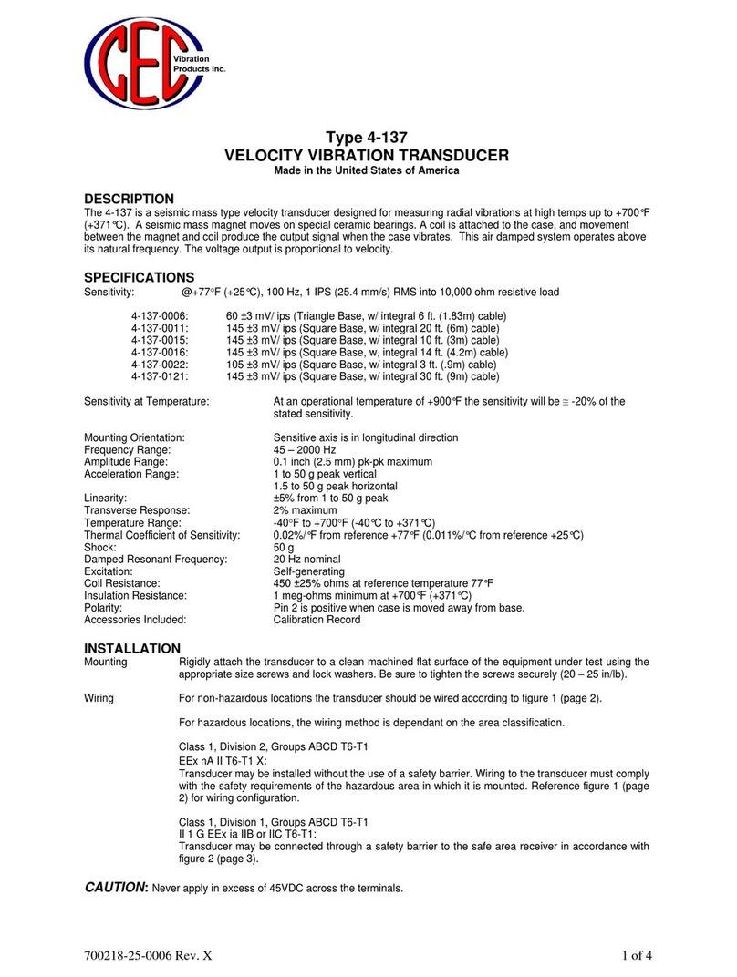
cec 4-137 User manual

cec

cec 4-137 User manual

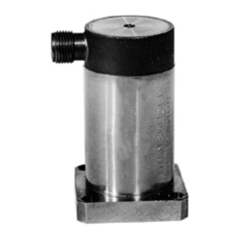
cec 4-131 User manual

cec

cec 4-131 User manual

Popular Transducer manuals by other brands

C-ducer CP Series User handbook

C-ducer

C-ducer CP Series User handbook

HBM PAD4001A quick start guide

HBM

HBM PAD4001A quick start guide

Trerice TA901 Installation, operation and maintenance instructions

Trerice

Trerice TA901 Installation, operation and maintenance instructions

Electrex ATTO D4 installation instructions

Electrex

Electrex ATTO D4 installation instructions

Veris Industries PW Series installation guide

Veris Industries

Veris Industries PW Series installation guide

S+S Regeltechnik PREMASGARD ALD Operating Instructions, Mounting & Installation

S+S Regeltechnik

S+S Regeltechnik PREMASGARD ALD Operating Instructions, Mounting & Installation

Humminbird XNT 9 20 installation guide

Humminbird

Humminbird XNT 9 20 installation guide

Camille Bauer SIRAX BT5500 Safety instruction

Camille Bauer

Camille Bauer SIRAX BT5500 Safety instruction

Daiichi Electronics VETT2-91A instruction manual

Daiichi Electronics

Daiichi Electronics VETT2-91A instruction manual

vacuubrand VSK 3000 Instructions for use

vacuubrand

vacuubrand VSK 3000 Instructions for use

SSET CE-VJ41 -9MSK-0.5 Series instructions

SSET

SSET CE-VJ41 -9MSK-0.5 Series instructions

LEYBOLD DI2000 operating instructions

LEYBOLD

LEYBOLD DI2000 operating instructions

novotechnik TM1 Series user manual

novotechnik

novotechnik TM1 Series user manual

Greystone Energy Systems LP-S installation instructions

Greystone Energy Systems

Greystone Energy Systems LP-S installation instructions

Setra Systems MS1 installation guide

Setra Systems

Setra Systems MS1 installation guide

controlair 2000 Installation, operation and maintenance instructions

controlair

controlair 2000 Installation, operation and maintenance instructions

turck IM12-TI01 Series quick start guide

turck

turck IM12-TI01 Series quick start guide

ATI Technologies Wireless F/T Compilation of Manuals

ATI Technologies

ATI Technologies Wireless F/T Compilation of Manuals

manuals.online logo
manuals.online logoBrands
  • About & Mission
  • Contact us
  • Privacy Policy
  • Terms and Conditions

Copyright 2025 Manuals.Online. All Rights Reserved.