Cedes UPS Plus User manual

English Pages 2 – 10
Deutsch Seiten 11 – 18
Français Pages 19 – 26
Italiano Pagine 27 – 34
Español Páginas 35 – 42
113 835 | 151019 | V 1.0
Installation and Operation Manual
UPS Plus
Universal Power Supply Plus
CEDES AG is certified according to ISO 9001: 2015
RoHS
C US

Universal Power Supply Plus (UPS Plus) English
2 © CEDES | V 1.0
1. About this manual
The UPS Plus - Universal Power Supply Plus Installation
and Operation Manual is the original version and features
metric and US measurements.
The version number is printed at the bottom of each page.
To make sure you have the latest version, visit
www.cedes.com where this manual and related documents
can be downloaded.
1.1 Measurements
Measurements are, if not stated otherwise, given in
mm (non-bracketed numbers) and inches (numbers in
brackets).
1.2 Related documents
UPS Plus datasheet
001 219 en
1.3 CEDES headquarter
CEDES AG
Science Park
CH-7302 Landquart
Switzerland
CEDES AG reserves the right to modify or change technical data without prior notice.
Contents
1. About this manual 2
1.1 Measurements 2
1.2 Related documents 2
1.3 CEDES headquarter 2
2. Safety information 3
2.1 Non-intended use 3
3. Symbols, safety messages 3
3.1 Safety messages categories 3
4. Introduction 4
4.1 Features of the UPS Plus 4
5. Installation 4
5.1 Switch OFF main power 4
5.2 Installation of the UPS Plus 4
6. Electrical connection 5
6.1 9-pin connector 5
6.2 6-pin connector 5
6.3 2-pin test connector 5
6.4 Wiring GridScan/Mini 6
6.5 Wiring cegard/Mini in combination
with IMS 100 7
6.6 Power-up and test for proper function 7
7. Trouble shooting 8
8. Technical Data 9
9. Dimensions 9

Universal Power Supply Plus (UPS Plus) English
© CEDES | V 1.0 3
2. Safety information
IMPORTANT!
READ BEFORE INSTALLATION!
The Universal Power Supply Plus (UPS Plus ) was developed
and manufactured using state-of-the-art systems and
technologies.
To ensure safe conditions:
Read all enclosed instructions and information
Follow the instructions given in this manual carefully
Observe all warnings included in the documentation
and attached to the UPS Plus
Keep the instruction manual on site
When the UPS Plus and a MiniMax or cegard/Mini light
curtain are used as a replacement for mechanical safety
edges, it is the responsibility of the installer to ensure
that on completion, the installation complies with all the
relevant state codes, local codes and regulations that
pertain to infrared and photoelectric door protection
devices!
The UPS Plus should only be installed by authorized and
fully trained personnel!
In Canada, particular attention should be given to clauses
2.13.5.1 and 2.13.5.2 CAN/CSA-B44-B89!
In the USA, all connections requiring 42 Volts or greater
must be wired through Greenfield tubing and fittings.
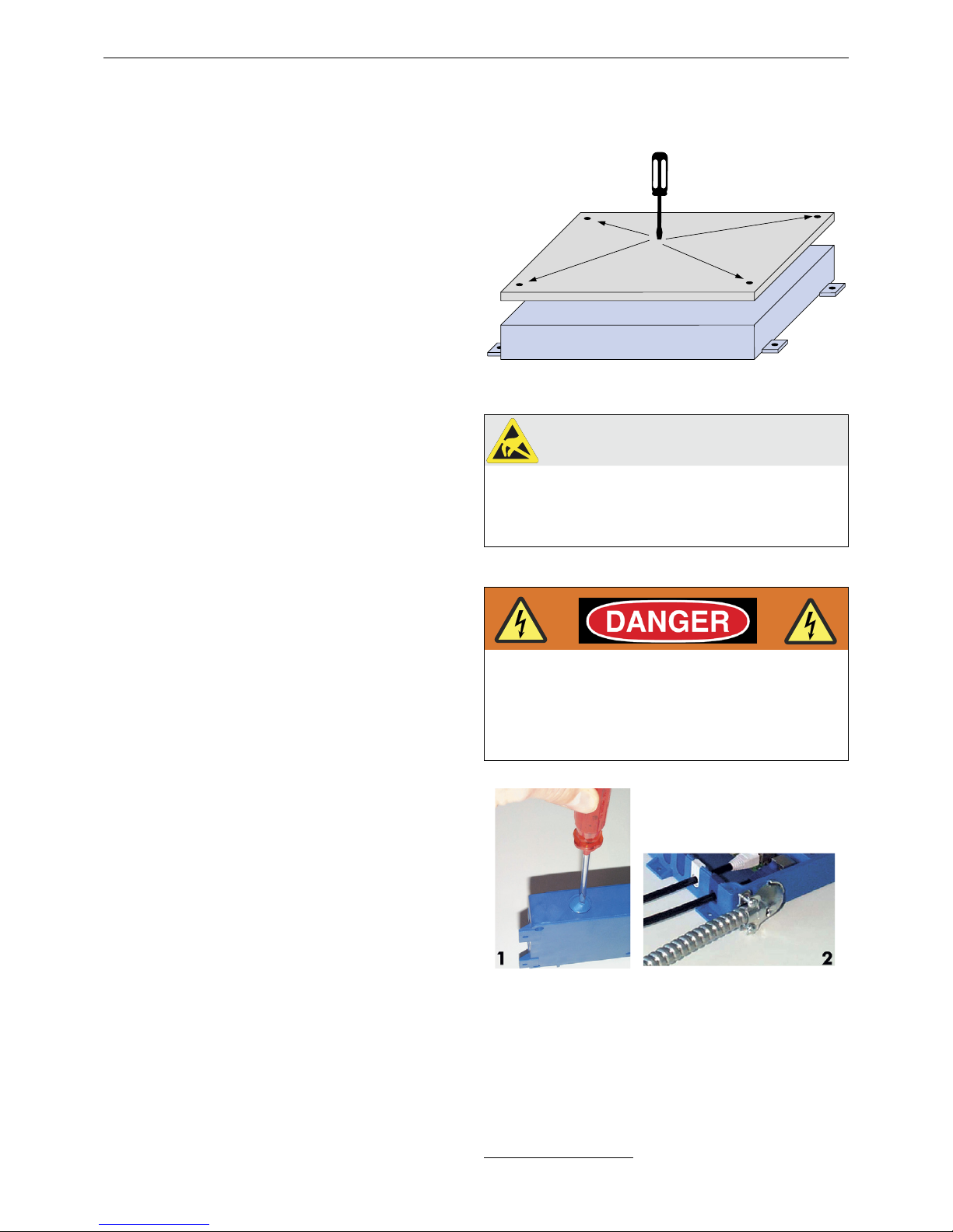
Disconnect power before opening the control unit to
prevent electrical shock. Do not remove any inside covers
or fuse caps.
2.1 Non-intended use
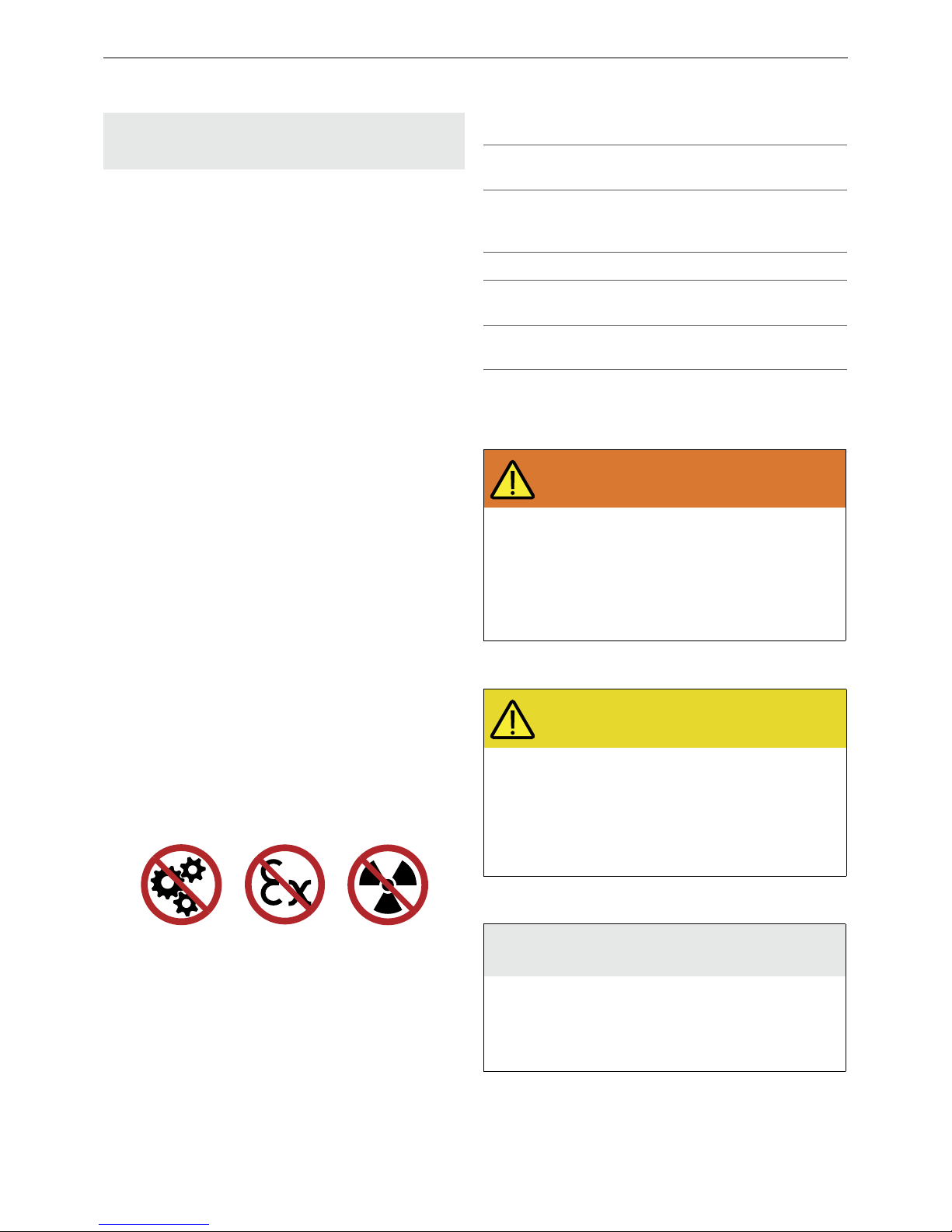
The UPS Plus must not be used for:
• Protection of dangerous machines
• Equipment in explosive atmospheres
• Equipment in radioactive environments
Use only specific and approved safety devices for such
applications, otherwise serious injury or death or damage
to property may occur!
3. Symbols, safety messages
3.1 Safety messages categories
Warning of serious health risks
WARNING
Serious health risks
Highlights critical information for the safe use
of the sensor. Disregarding these warnings
can result in serious injury or death.
Follow the measures highlighted by the
triangle-shaped arrows
Consult the safety information in Chapter
2 of this manual
Caution of possible health risk
CAUTION
Possible health risks
Highlights critical information for the safe
use of the sensor. Disregarding these
warnings can result in injury.
Follow the measures highlighted by the
triangle-shaped arrows
Consult the safety information in Chapter
2 of this manual
Notice of damage risk
NOTICE
Risk of damage
Disregarding these notices can lead to
damage to the sensor, the door controller
and/or other devices.
Follow the measures highlighted by the
triangle-shaped arrows
Symbol Meaning
Single instruction or measures in no
particular order
1.
2.
3.
Sequenced instructions
• List, in no order of importance
àReference to a chapter, illustration or
table within this document
Important Important information for the correct
use of the sensor

Universal Power Supply Plus (UPS Plus) English
4 © CEDES | V 1.0
4. Introduction
The UPS Plus has two potential-free relay outputs and
enables the simultaneous connection of two sensors (e.g.
cegard/Mini combined with an IMS 100). It also offers a
test input. When a door control system operates with a
test signal, this can be connected directly to the UPS Plus.
To do so, the test DIP switch must be set to ON. If it is
preferable to operate the light curtain without testing, the
test DIP switch should be set to OFF. That way, the test
signal is internally connected with a 24 VDC voltage.
Important:
The UPS Plus is not a TÜV certified device that can handle
a test routine by itself.
The UPS Plus consists of the controller and the required
plugs to connect the power supply, the outputs and the
sensor.
4.1 Features of the UPS Plus
• Electrical isolation between high and low power side
• Two independent sensor inputs
• Test signal feed through
• Robust housing with an IP54 enclosure rating
• On/Off buzzer function
• EMC filter ensures trouble-free operation
• Two potential-free relay outputs
5. Installation
The installation should be done in the following sequence:
1. Switch main power off and mark clearly that this
unit/equipment is out of service.
2. Install the sensor and cables.
3. Mount the UPS Plus.
4. Carry out the electrical installation.
5. Power-up and test for proper function.
5.1 Switch OFF main power
For your own safety, turn the power off before you start
working on the unit/equipment! Clearly mark that this
unit/equipment is out of service.
5.2 Installation of the UPS Plus
The UPS Plus unit can be mounted horizontally or vertically
with 4 screws near the door drive.
Figure 1: Installation of the UPS Plus
NOTICE
The PCB is sensitive to electrostatic discharge
and must be handled with care to prevent
callbacks. Use anti-static procedures when
handling these boards.
For the USA and Canada:
Figure 2: 1. Knockout hole for Greenfield fitting
2. Final installation of the Greenfield fitting3
3 From T&B or other UL/CSA approved manufacturer
Connect all wiring with more than 42 V
through a Greenfield fitting.
Disconnect power before opening the
UPS Plus to prevent electrical shock.
Otherwise serious injury or death may
occur!

Universal Power Supply Plus (UPS Plus) English
© CEDES | V 1.0 5
6. Electrical connection
• The 9-pin connector must be plugged into the 9-pin plug. This connector is for the two relay outputs and for the
power supply (see Chapter 6.1).
• The 6-pin connector must be plugged into the 6-pin plug. This connector is for the sensor connection (see Chapter 6.2).
• The 2-pin connector must be plugged into the 2-pin plug. This connector is for a test signal; if available (see Chapter 6.3).
Important:
The UPS Plus test input cannot handle a test routine by itself.
6.1 9-pin connector
The 9-pin connector is for the power supply input and for the two relay outputs.
Power supply
N : AC neutral, plus or minus for DC
P : AC hot, plus or minus for DC
: Protective ground
Output relays
The maximum contact rating for the two relay outputs is:
250 VAC / 5 A
25 VDC / 0.5 A
30 VDC / 5 A
min. 5 VDC / 10 mA
6.2 6-pin connector
The 6-pin connector is for the sensor connection.
Sensor connection output
24 VDC ±10%
GND (0 V)
Test_out: Test signal from extenal controller if test DIP switch is on.
HIGH if test DIP switch is off.
Log_selector connects the logic selector to GND. Check logic selector of
the connected sensor to decide if it has to be connected.
Sensor connection input
Input 1: Activates relay 1
Input 2: Activates relay 2
6.3 2-pin test connector
The 2-pin test connector does not generate a test signal. If the external controller generates a test signal, it can be
connected to the UPS Plus. Set the corresponding DIP switch to ON. The signal will then be “wired through”, galvanically
separated. If the controller cannot handle a test signal, the DIP switch has to be set to OFF. In this case, the test signal
will be connected to the internal supply voltage of the UPS Plus (24 VDC).
Important:
The UPS Plus test input cannot handle a test routine by itself.
Test input + 24 VDC connection
Test input - GND (0 V) connection
Output
relay 1
Power
N
COM
NC
NO
Output
relay 2
COM
NC
NO
L
V V
V
V V
V
V VV
Sensor connection
24 V
0 V
Input 1
Input 2
Test_out
Logic_sel
VV
V
V
VV
Test
Test+
Test-
VV

Universal Power Supply Plus (UPS Plus) English
6 © CEDES | V 1.0
6.4 Wiring GridScan/Mini
Follow the wiring diagram (Figure 3) to connect e.g GridScan/Mini with a single element detection signal to the door
controller. For the functional description for the GridScan/Mini safety light curtain please refer to the manual on
www.cedes.com.
Figure 3: Wiring of the UPS Plus with the GridScan/Mini safety light curtain
NO
COM
NC
NO
USP
GND
COM
NC
Buzzer
Test
ON
OFF
LED
Power
Green
Power OK
No power
ON
OFF
Orange Red
Input 1 Input 2 Outputs
-
Test
Test+
Test-
VV
Sensor connection
24 V
0 V
Input 1
Input 2
Test_out
Logic_sel
VV
V
V
VV
Output
relay 1
Power
N
COM
NC
NO
Output
relay 2
COM
NC
NO
L
V V
V
V V
V
V VV
UPS Plus LED definition:
- Power LED (green) is ON, if supply voltage is connected correctly.
- Input LED (orange) is ON, if the protected area is obstructed.
- Input LED (red) is ON, if the protected area is obstructed.
Relay definition:
In the configuration shown, the relay is energized if there is
voltage applied and there is no obstruction. Contact between
COM and NO (safest connection).
Buzzer definition:
- Buzzer is OFF, if the protected area (light curtain) is not obstructed.
- The buzzer can be turned on/off by using a switch.
L
N
Protective
ground
Supply voltage:
20 ... 265 VAC
20 ... 375 VDC
GridScan/Mini
output relay 1
To the
door controller
Single element detection
output relay 2
GridScan/Mini
safety light curtain
Single element
detection
Test input
GridScan/Mini
Output
Logic selector
Input test signal
from the
door controller
brown
blue
black
green
white
gray

Universal Power Supply Plus (UPS Plus) English
© CEDES | V 1.0 7
6.5 Wiring cegard/Mini in combination with IMS 100
Follow the wiring diagram (Figure 4) to connect e.g a cegard/Mini in combination with a IMS100 to the elevator
controller. For the functional description of the cegard/Mini light curtain and the IMS 100 please refer to the manuals
on www.cedes.com.
Figure 4: Wiring of the UPS Plus with the cegard/Mini light curtain in combination with the IMS 100 3D sensor
6.6 Power-up and test for proper function
Turn on power after the sensor has been correctly installed
in conjunction with the UPS Plus. The start-up time for the
UPS Plus takes max. 4 s.
The green LED in the UPS Plus indicates that there is supply
voltage available.
An orange LED indicates the status of the sensor input 1
and the output relay 1.
A red LED indicates the status of the sensor input 2 and
the output relay 2.
NO
COM
Buzzer
Test
ON
OFF
LED
Power
Green
Power OK
No power
ON
OFF
Orange Red
Input 1 Input 2 Outputs
-
Test
Test+
Test-
VV
Sensor connection
24 V
0 V
Input 1
Input 2
Test_out
Logic_sel
VV
V
V
VV
Output
relay 1
Power
N
COM
NC
NO
Output
relay 2
COM
NC
NO
L
V V
V
V V
V
V VV
IMS 100
L
N
Emitter Receiver
UPS Plus LED definition:
- Power LED (green) is ON, if supply voltage is connected correctly.
- Input LED (orange) is ON, if the protected area is obstructed.
- Input LED (red) is ON, if the protected area is obstructed.
Relay definition:
In the configuration shown, the relay is energized if there is
voltage applied and there is no obstruction. Contact between
COM and NO (safest connection).
* Time-out selector connection (white wire) has to be connected (depending on the requested time-out setting)
Time-out setting
Connect the white wire from IMS 100 to 24 VDC for 18 s **
Connect the white wire from IMS100 to GND (0 V) for Infinity
For more details refer to the IMS 100 manual on www.cedes.com
** The timer begins to count after the first sensor triggering. After this time the sensor will be disabled until the
next door opening.
Buzzer definition:
- Buzzer is OFF, if the protected area (light curtain) is not obstructed.
- The buzzer can be turned on/off by using a switch.
Protective
ground
Supply voltage:
20 ... 265 VAC
20 ... 375 VDC
Output relay 1
To the
elevator controller
Output relay 2
blue
black
white
brown
blue
brown
black
white
*
Orange LED Sensor input 1 Output relay 1
ON LOW COM = NC
OFF HIGH COM = NO
Red LED Sensor input 2 Output relay 2
ON LOW COM = NC
OFF HIGH COM = NO

Universal Power Supply Plus (UPS Plus) English
8 © CEDES | V 1.0
7. Trouble shooting
If a problem persists, please contact your local CEDES representative. Visit www.cedes.com for contact data.
Fault / Problem Action
Door remains
open; green and
orange LED OFF
Is the power supply OK?
Measure the main power on the connector. The main power must be 20 … 265 VAC or
20 ... 375 VDC.
Check the power LED (green) on the UPS Plus.
Is any wire broken?
Measure and check the main power cables.
Door remains
open; protective
area is free
Is the sensor correctly connected to the UPS Plus?
Make sure that the sensor cables are connected to the 6 pin connector of the UPS Plus.
Is the grounding (PE) connection faulty?
Make sure that the grounding (PE) is connected to the UPS Plus.
Is there excessive EMC interference e.g. from door drive?
Do not guide the connection cables of the optical sensor close to cables carrying high voltage
and/or high current. The cables should also be mounted as far away as possible from the
door drive motor or motor inverter (VVVF-drives) to avoid EMI problems.
Is there excessive light interference e.g. from fluorescent lamps?
Do not install the receiver part of the optical sensor directly exposed to light sources such as
FL tubes or energy-saving lamps.
If a light curtain is connected:
It is important that the active parts of the emitter and receiver units are mounted so that they
face each other. The active sensor part is the side with the black round lenses.
Are the sensors or vision shields dirty?
The active sensor part is the side with the black round lenses. Make sure that the black lenses
are clean and not painted or scratched.
Make sure that the vision shields are not painted or scratched.
Is any beam interrupted?
Make sure that no object blocks the light path between emitter and receiver while the door
is open and while the door is closing.
Are the edges incorrectly aligned?
The optical axis of the emitter (Tx) and the receiver edge (Rx) need to be aligned towards
each other to ensure the light curtain functions reliably.
Random door
openings
Is the sensor cable damaged?
Check for breaks in the cables by feeling the cables by hand.
Is there any interference with the emitter from other infrared sensors (either directly or via
mirroring from shiny surfaces)?
Avoid interference from blinking lights or infrared light sources such as photo cells or other
optical sensors.
Reflective surfaces near or parallel to the safeguarded area can cause reflections.

Universal Power Supply Plus (UPS Plus) English
© CEDES | V 1.0 9
8. Technical Data
9. Dimensions
Metric measurements (all dimensions in mm)
Mechanical
Dimensions (w × h × d) 200 × 45 × 128 mm
(7.9 × 1.77 × 5.05 in)
Housing material ABS
Housing color Blue
Enclosure rating IP54
Temperatur range −20 °C ... +60 °C
(−5 °F ... +140 °F)
General
EMC emmision EN 61000-6-3:2007
EN 12015:2014
EMC immunity EN 61000-6-2:2005
EN 12016:2013
Vibration IEC 60068-2-6:2007
Shock IEC 60068-2-27:2008
RoHS 2011/65/EU
Certificates CE, CSA
Electrical
Supply voltage USP 20 ... 265 VAC
20 ... 375 VDC
Current consumption < 30 mA at 24 VDC
(without load) < 45 mA at 240 VAC
Inrush current 1.5 A
DC output voltage 24 V ±10%
Output rated current 300 mA at 24 VDC
Output rated capacitance 500 μF
Relay outputs Max. 250 VAC / 5 A
Max. 125 VDC / 0.5 A
Max. 30 VDC / 5 A
Min. 5 VDC / 10 mA
Max. power-up time 4 s
Max. relay switching time 10 ms
Max. propagation delay 5 ms
test signal
3 LED indicators Green Power
Orange Output relay 1
Red Output relay 2
Buzzer
Test
ON
OFF
Test
Test+
Test-
VV
Sensor connection
24 V
0 V
Input 1
Input 2
Test_out
Logic_sel
VV
V
V
VV
LED
Power
Green
Power OK
No power
ON
OFF
Orange Red
Input 1 Input 2 Outputs
-
Output
relay 1
Power
N
COM
NC
NO
Output
relay 2
COM
NC
NO
L
V V
V
V V
V
V VV
45
80
160
130
188
200
5
128
45
80
160
130
188
200
5
128

Universal Power Supply Plus (UPS Plus) English
10 © CEDES | V 1.0
US measurements (all dimensions in inches)
Buzzer
Test
ON
OFF
Test
Test+
Test-
VV
Sensor connection
24 V
0 V
Input 1
Input 2
Test_out
Logic_sel
VV
V
V
VV
LED
Power
Green
Power OK
No power
ON
OFF
Orange Red
Input 1 Input 2 Outputs
-
Output
relay 1
Power
N
COM
NC
NO
Output
relay 2
COM
NC
NO
L
V V
V
V V
V
V VV
1.77
3.15
6.3
5.1
7.4
7.9
0.19
5.05

Universal Power Supply Plus (UPS Plus) Deutsch
© CEDES | V 1.0 11
1. Über diese Anleitung
Die englische Originalfassung «UPS Plus - Universal
Power Supply Plus Installation and Operation Manual» ist
die rechtsverbindliche Fassung. Masse werden darin nach
dem metrischen System angegeben.
Die Versionsnummer ist am unteren Rand jeder Seite
abgedruckt.
Die aktuelle Version dieser Anleitung sowie verwandte
Dokumente können auf www.cedes.com heruntergeladen
werden.
1.1 Massangaben
Masse werden in mm (Zahlen ohne Klammern)
angegeben, sofern nicht ausdrücklich anders festgelegt.
1.2 Verwandte Dokumente
UPS Plus Datenblatt
001 219 de
1.3 CEDES Hauptsitz
CEDES AG
Science Park
CH-7302 Landquart
Schweiz
Inhalt
1. Über diese Anleitung 11
1.1 Massangaben 11
1.2 Verwandte Dokumente 11
1.3 CEDES Hauptsitz 11
2. Sicherheitshinweise 12
2.1 Nicht bestimmungsgemässe Verwendung 12
3. Symbole und Sicherheitshinweise 12
3.1 Warnhinweiskategorien 12
4. Einleitung 13
4.1 Merkmale des UPS Plus 13
5. Montage 13
5.1 Ausschalten der Stromversorgung 13
5.2 Montage des UPS 13
6. Elektrische Montage 14
6.1 9-poliger Stecker 14
6.2 6-poliger Stecker 14
6.3 2-poliger Stecker für Testanschluss 14
6.4 Verdrahtung mit GridScan/Mini 15
6.5 Verdrahtung mit cegard/Mini
in Kombination mit IMS 100 16
6.6 Einschalten und Funktionstest 16
7. Fehlerbehebung 17
8. Technische Daten 18
9. Abmessungen 18
CEDES AG behält sich das Recht vor, technische Daten
ohne Vorankündigung dem Stand der Technik anzupassen.

Universal Power Supply Plus (UPS Plus) Deutsch
12 © CEDES | V 1.0
2. Sicherheitshinweise
WICHTIG!
VOR DER MONTAGE LESEN!
Das Universelle Netzgerät UPS Plus (Universal Power
Supply Plus) wurde mit Technologien entwickelt und
gefertigt, die dem neuesten Stand der Technik entsprechen.
Für sichere Arbeits- und Betriebsbedingungen:
Alle relevanten Dokumente lesen
Alle Anweisungen in dieser Anleitung befolgen
Alle Warnungen in dieser Anleitung und auf dem UPS
Plus beachten
Bedienungsanleitung vor Ort aufbewahren
Wenn das UPS Plus und der MiniMax- bzw. cegard/Mini-
Lichtvorhang als Ersatz für mechanische Sicherheitsleisten
verwendet werden, liegt es in der Verantwortung des
Monteurs sicherzustellen, dass die Montage nach
Fertigstellung allen relevanten Gesetzen und Vorschriften
zu Infrarot-Türabsicherungen und photoelektrischen
Türabsicherungen entspricht!
Das UPS Plus darf nur von autorisiertem und umfassend
geschultem Personal montiert werden!
In Kanada sind besonders die Klauseln 2.13.5.1 und
2.13.5.2 von CAN/CSA-B44-B89 zu beachten! In den
USA müssen alle Verbindungen, die 42 Volt oder mehr
erfordern, über Greenfield-Rohre und -Anschlussstücke
hergestellt werden. Trennen Sie die Stromversorgung
vor dem Öffnen des Kontrollers ab, um Stromschläge zu
verhindern. Entfernen Sie aus Sicherheitsgründen keine
befestigten Abdeckungen oder Sicherungskappen.
2.1 Nicht bestimmungsgemässe
Verwendung
Das UPS Plus darf nicht eingesetzt werden:
• Zum Schutz von gefährlichen Maschinen
• Anlagen in explosiven Atmosphären
• Anlagen in radioaktiven Atmosphären
Für Anwendungen dieser Art dürfen nur spezielle, dafür
zugelassene Sicherheitsvorrichtungen eingesetzt werden.
Andernfalls kann dies zu schweren Verletzungen,
Todesfällen oder Sachschäden führen!
3. Symbole und
Sicherheitshinweise
3.1 Warnhinweiskategorien
Warnung vor schwerwiegenden Gesundheits-
gefahren
WARNUNG
Schwerwiegende Gesundheits-
gefahren
Enthält wichtige Informationen zur sicheren
Nutzung des Sensors. Nichtbeachten dieser
Warnungen kann zu schweren Verletzungen
oder zum Tod führen.
Handlungsaufforderungen nach drei-
eckigen Pfeilen befolgen
Die Sicherheitshinweise in Kapitel 2 dieser
Anleitung beachten
Hinweis auf mögliche Gesundheitsgefahren
VORSICHT
Mögliche Gesundheitsgefahren
Weist auf wesentliche Informationen zum
sicheren Gebrauch des Sensors hin.
Nichtbeachten dieser Hinweise kann zu
Verletzungen führen.
Handlungsaufforderungen nach drei-
eckigen Pfeilen befolgen
Die Sicherheitshinweise in Kapitel 2 dieser
Anleitung beachten
Hinweis auf Sachschäden
HINWEIS
Gefahr von Sachschäden
Nichtbeachten dieser Hinweise kann zu
Schäden am Sensor, der Türsteuerung und/
oder anderen Einrichtungen führen.
Handlungsaufforderungen nach drei-
eckigen Pfeilen befolgen
Symbol Bedeutung
Einzelne Handlungsaufforderung ohne
bestimmt Reihenfolge
1.
2.
3.
Handlungsaufforderung in einer
bestimmten Reihenfolge
• Aufzählungspunkt, Reihenfolge ist
unerheblich
àVerweis auf ein Kapitel, eine
Abbildung oder Tabelle in diesem
Dokument
Important Wichtige Informationen zur richtigen
Nutzung des Sensors

Universal Power Supply Plus (UPS Plus) Deutsch
© CEDES | V 1.0 13
4. Einleitung
Das universelle Netzgerät UPS Plus ist mit zwei
potenzialfreien Relaisausgängen ausgestattet und
ermöglicht den gleichzeitigen Anschluss zweier Sensoren
(z.B. Kombination von cegard/Mini und IMS 100).
Darüber hinaus verfügt es über einen Testeingang.
Verwendet eine Türsteuerung ein Testsignal, so kann eine
Direktverbindung mit dem UPS Plus hergestellt werden.
Dazu muss der Test-DIP-Schalter eingeschaltet sein.
Sollte der Lichtvorhang ohne Test verwendet werden und
der Test-DIP-auf OFF gestellt sein. Auf diese Weise wird
das Testsignal intern mit einer Spannung von 24 VDC
verbunden.
Wichtig:
Das UPS Plus ist kein TÜV-zertifiziertes Gerät, das eine
Testroutine selbstständig durchführen kann.
Das UPS Plus besteht aus der Steuerung und den für den
Anschluss von Stromversorgung, Ausgängen und Sensor
benötigten Steckern.
4.1 Merkmale des UPS Plus
• Elektrische Isolation zwischen Primär- und Sekundärseite
• Zwei unabhängige Sensoreingänge
• Testsignal-Durchführung
• Robustes Gehäuse (Schutzklasse IP54)
• Ein- und ausschaltbare Summer-Funktion
• Integrierter EMV-Filter für einen störungsfreien Betrieb
• Zwei potentialfreie Relaisausgänge
5. Montage
Die Montage sollte in der folgenden Abfolge durchgeführt
werden:
1. Ausschalten der Stromversorgung und deutliche
Kennzeichnung der Anlage/Einrichtung als «Ausser
Betrieb»
2. Montage des Sensors und Kabel
3. Montage des UPS Plus
4. Elektrische Montage
5. Einschalten und Funktionstest
5.1 Ausschalten der Stromversorgung
Schalten Sie zu Ihrer eigenen Sicherheit die
Stromversorgung aus, bevor Sie mit Arbeiten an der
Anlage/Einrichtung beginnen! Kennzeichnen Sie die
betreffende Anlage/Einrichtung deutlich als «Ausser
Betrieb».
5.2 Montage des UPS
Das UPS Plus kann mit vier Schrauben in der Nähe des
Türantriebs horizontal oder vertikal montiert werden.
Abb 1: Montage des UPS Plus
HINWEIS
Die Leiterplatte ist empfindlich gegen elektro-
statische Entladungen und muss vorsichtig
behandelt werden, um Rückrufe zu vermeiden.
Arbeiten Sie mit diesen Geräten immer anti-
statisch.
Für USA und Canada:
Abb 2: 1. Ausbrechloch für das Greenfield-Anschlussstück
2. Endmontage mit dem Greenfield-Anschlussstück3
3 von T&B oder einem anderen Hersteller mit UL/CSA-
Zulassung
Alle Anschlüsse mit mehr als 42 V über ein
Greenfield-Anschlussstück anschliessen.
Die Stromversorgung vor dem Öffnen des
UPS Plus abtrennen, um Stromschläge
zu verhindern. Nichtbeachten kann zu
schweren Verletzungen oder zum Tod
führen.

Universal Power Supply Plus (UPS Plus) Deutsch
14 © CEDES | V 1.0
6. Elektrische Montage
• Der 9-poliger Stecker muss an die 9-polige Steckerbuchse angeschlossen werden. Dieser Anschluss ist für die beiden
Relaisausgänge und für die Stromversorgung (siehe Kapitel 6.1).
• Der 6-poliger Stecker muss an die 6-polige Steckerbuchse angeschlossen werden. Dieser Anschlus ist für den
Sensoranschluss (siehe Kapitel 6.2).
• Der 2-poliger Stecker muss an die 2-polige Steckerbuchse angeschlossen werden. Dieser Anschluss ist für ein
Testsignal, falls vorhanden (siehe Kapitel 6.3).
Wichtig:
Der Testeingang des UPS Plus kann selbst keine Testroutine durchführen.
6.1 9-poliger Stecker
Der 9-poliger Stecker ist für die Stromversorgung (Eingang) und für die beiden Relaisausgänge.
Stromversorgung
N : Null-Leiter, plus oder minus für DC
P : Phase für AC, plus oder minus für DC
: Schutzerde
Ausgangsrelais
Die maximalen Anschlusswerte der beiden Ausgangsrelais sind:
250 VAC / 5 A
25 VDC / 0.5 A
30 VDC / 5 A
min. 5 VDC / 10 mA
6.2 6-poliger Stecker
Der 6-poliger Stecker ist für den Sensoranschluss.
Anschluss für Sensorausgang
24 VDC ±10%
GND (0 V)
Test_out: Testsignal des externen Kontrollers, wenn der Test-DIP-Schalter
EIN ist. HIGH, wenn der Test-DIP-Schalter AUS ist.
Logic_sel: Schliesst den Logik-Selektor des Sensors an GND an. Logik-
Selektor des angeschlossenen Sensors überprüfen um zu entscheiden, ob
er angeschlossen werden muss.
Anschluss für Sensoreingang
Input 1: Aktiviert Relais 1
Input 2: Aktiviert Relais 2
6.3 2-poliger Stecker für Testanschluss
Der 2-polige Testanschluss generiert kein Testsignal. Generiert die externe Steuerung ein Testsignal, kann dieses an das
UPS Plus angeschlossen werden. Entsprechenden DIP-Schalter auf ON stellen. Das Signal wird anschliessend galvanisch
getrennt "durchgeschleift". Kann die Steuerung kein Testsignal verarbeiten, muss der DIP-Schalter auf OFF gestellt
werden. In diesem Fall wird das Testsignal an die interne Versorgungsspannung des UPS Plus (24 VDC) angeschlossen.
Wichtig:
Der Testeingang des UPS Plus kann selbst keine Testroutine durchführen.
Test input + 24 VDC Anschluss
Test input - GND (0 V) Anschluss
Output
relay 1
Power
N
COM
NC
NO
Output
relay 2
COM
NC
NO
L
V V
V
V V
V
V VV
Sensor connection
24 V
0 V
Input 1
Input 2
Test_out
Logic_sel
VV
V
V
VV
Test
Test+
Test-
VV

Universal Power Supply Plus (UPS Plus) Deutsch
© CEDES | V 1.0 15
6.4 Verdrahtung mit GridScan/Mini
Der Anschlussplan (Abbildung 3) zeigt, wie z.B. ein GridScan/Mini in Verbindung mit einem Signal zur Einzelelement-
Detektion an die Türsteuerung anzuschliessen ist. Eine Funktionsbeschreibung des Sicherheitslichtvorhangs
GridScan/Mini ist in der Anleitung auf www.cedes.com enthalten.
Abb 3: Verdrahtung zwischen UPS Plus und dem Sicherheitslichtvorhang GridScan/Mini
NO
COM
NC
NO
USP
GND
COM
NC
Buzzer
Test
ON
OFF
LED
Power
Green
Power OK
No power
ON
OFF
Orange Red
Input 1 Input 2 Outputs
-
Test
Test+
Test-
VV
Sensor connection
24 V
0 V
Input 1
Input 2
Test_out
Logic_sel
VV
V
V
VV
Output
relay 1
Power
N
COM
NC
NO
Output
relay 2
COM
NC
NO
L
V V
V
V V
V
V VV
LED-Anzeigen UPS Plus:
- Betriebskontroll-LED (grün) ist EIN, wenn die Versorgungsspannung
korrekt angeschlossen ist.
- Eingangs-LED (orange) is EIN, wenn der geschützte Bereich durch
Hindernisse unterbrochen ist.
- Eingangs-LED (rot) ist EIN, wenn der geschützte Bereich durch
Hindernisse unterbrochen ist.
Relaiskonfiguration:
In der abgebildeten Konfiguration ist das Relais aktiviert
(angezogen), wenn Spannung anliegt und kein Hindernis vor-
handen ist. Kontakt zwischen COM und NO (sicherste Schaltung).
Akkustischer Alarm:
- Akustischer Alarm ist AUS, wenn der geschützte Bereich
(Lichtvorhang) frei von Hindernissen ist.
- Der akustische Alarm kann mit einem Schalter ein- bzw.
ausgeschaltet werden.
L
N
Schutzerde
Versorgungsspannung:
20 ... 265 VAC
20 ... 375 VDC
GridScan/Mini
Ausgangsrelais 1
Zur
Türsteuerung
Einzelelement-Detektion
Ausgangsrelais 2
Sicherheitslichtvorhang
GridScan/Mini
Einzelelement-
Detektion
Testeingang
GridScan/Mini
Ausgang
Logik-Selektor
Eingang Testsignal
von der Türsteuerung
braun
blau
schwarz
grün
weiss
grau

Universal Power Supply Plus (UPS Plus) Deutsch
16 © CEDES | V 1.0
6.5 Verdrahtung mit cegard/Mini in Kombination mit IMS 100
Der Anschlussplan (Abbildung 4) zeigt, wie z.B. ein cegard/Mini in Verbindung mit einem IMS 100 an die Aufzugsteuerung
anzuschliessen ist. Eine Funktionsbeschreibung des Lichtvorhangs cegard/Mini und des IMS 100 ist in den Anleitungen
auf www.cedes.com enthalten.
Abb 4: Verdrahtung des UPS Plus mit dem Lichtvorhang cegard/Mini in Kombination mit dem 3D-Sensor IMS 100
6.6 Einschalten und Funktionstest
Schalten Sie nach der korrekten Montage des Sensors in
Verbindung mit dem UPS Plus die Stromversorgung ein.
Die Aufstartzeit für das UPS Plus beträgt max. 4 s.
Die grüne LED im UPS Plus zeigt an, dass eine
Versorgungsspannung verfügbar ist.
Eine orangefarbene LED zeigt den Status des
Sensoreingangs 1 und des Ausgangsrelais 1 an.
Eine rote LED zeigt den Status des Sensoreingangs 2 und
des Ausgangsrelais 2 an.
Buzzer
Test
ON
OFF
LED
Power
Green
Power OK
No power
ON
OFF
Orange Red
Input 1 Input 2 Outputs
-
Test
Test+
Test-
VV
Sensor connection
24 V
0 V
Input 1
Input 2
Test_out
Logic_sel
VV
V
V
VV
Output
relay 1
Power
N
COM
NC
NO
Output
relay 2
COM
NC
NO
L
V V
V
V V
V
V VV
IMS 100
*
Sender Empfänger
LED-Anzeigen des UPS Plus:
- Betriebskontroll-LED (grün) ist EIN, wenn die Versorgungsspannung
korrekt angeschlossen ist.
- Eingangs-LED (orange) ist EIN,
wenn der geschützte Bereich durch
Hindernisse unterbrochen ist.
- Eingangs-LED (rot) ist EIN, wenn der geschützte Bereich durch
Hindernisse unterbrochen ist.
Relaiskonfiguration:
In der abgebildeten Konfiguration ist das Relais aktiviert
(angezogen), wenn Spannung anliegt und kein Hindernis
vorhanden ist. Kontakt zwischen COM und NO
(sicherste Schaltung).
* Anschluss Time-out Selektor (weisse Ader, je nach benötigter Time-out-Einstellung)
Time-out Einstellungen
Für die Einstellung «18 s**» weisse Ader vom IMS 100 an 24 VDC anschliessen
Für die Einstellung «unendlich» weisse Ader vom IMS 100 an GND (0 V) anschliessen
Weitere Details zu IMS 100 sind in der Bedienungsanleitung unter www.cedes.com zu finden
** Der Timer beginnt mit der Zählung ab der ersten Sensorauslösung. Nach dieser Zeit wird der Sensor bis zum nächsten
Öffnen der Tür abgeschaltet.
Akustischer Alarm:
- Akustischer Alarm ist AUS, wenn der geschützte Bereich
(Lichtvorhang) frei von Hindernissen ist.
- Der akustische Alarm kann mit einem Schalter ein- bzw.
ausgeschaltet werden.
Schutzerde
Versorgungsspannung:
20 ... 265 VAC
20 ... 375 VDC
Ausgangsrelais 1
Zur
Aufzugs-
steuerung
Ausgangsrelais 2
blau
schwarz
weiss
braun
blau
braun
schwarz
weiss
*
NO
COM
L
N
Orange LED Sensoreingang 1 Ausgangsrelais 1
EIN LOW COM = NC
AUS HIGH COM = NO
Rote LED Sensoreingang 2 Ausgangsrelais 2
EIN LOW COM = NC
AUS HIGH COM = NO

Universal Power Supply Plus (UPS Plus) Deutsch
© CEDES | V 1.0 17
7. Fehlerbehebung
Wenn ein Problem weiterhin besteht, wenden Sie sich an den für Sie zuständigen CEDES-Vertreter. Die Kontaktdaten
finden Sie unter www.cedes.com.
Fehler / Problem Massnahme
Tür bleibt geöff-
net; grüne und
orangefarbene
LED sind AUS
Ist die Stromversorgung in Ordnung?
Netzspannung am Anschluss messen. Die Netzspannung muss 20 … 265 VAC oder
20 ... 375 VDC betragen.
Betriebskontroll-LED (grün) am UPS Plus prüfen.
Ist ein Kabelbruch vorhanden?
Netzkabel messen und prüfen.
Tür bleibt
geöffnet; über-
wachter Bereich ist
nicht unterbrochen
Ist der optische Sensor korrekt an das UPS Plus angeschlossen?
Sicherstellen, dass die Sensorkabel mit dem 6-poligen Anschlussstecker des UPS Plus
verbunden sind.
Ist der Erdungsanschluss (PE) defekt?
Sicherstellen, dass die Erdung (PE) an das UPS Plus angeschlossen ist.
Gibt es starke EMV-Störungen, z. B. durch den Türantrieb?
Anschlusskabel des optischen Sensors nicht in der Nähe von Kabeln verlegen, die hohe
Spannungen und/oder hohe Ströme führen. Zur Vermeidung von EMV-Problemen sollten
die Kabel auch möglichst weit vom Motor des Türantriebs oder dem Motorumrichter
(VVVFAntriebe) entfernt sein.
Gibt es starke Störungen durch Fremdlicht, z. B. Leuchtstofflampen?
Den Empfänger des optischen Sensors nicht so montieren, dass er Lichtquellen wie
Leuchtstoffröhren oder Energiesparlampen direkt ausgesetzt ist.
Bei Anschluss eines Lichtvorhangs:
Die aktiven Teile von Sender- und Empfängereinheit müssen exakt aufeinander ausgerichtet
montiert sein. Der aktive Sensorteil liegt an der Seite mit den schwarzen, runden Linsen.
Sind die Sensoren oder das Vision Shield verschmutzt?
Der aktive Sensorteil liegt an der Seite mit den runden, schwarzen Linsen. Sicherstellen,
dass die schwarzen Linsen sauber und nicht mit Farbe überstrichen oder zerkratzt sind.
Sicherstellen, dass das Vision Shield nicht mit Farbe überstrichen oder zerkratzt ist.
Ist ein Strahl unterbrochen?
Sicherstellen, dass kein Objekt den Lichtpfad zwischen Sender und Empfänger blockiert,
während die Tür geöffnet ist oder während sie sich schliesst.
Sind die Leisten nicht korrekt ausgerichtet?
Die optische Achse des Senders (Tx) und Empfängers (Rx) muss aufeinander ausgerichtet
sein, um einen zuverlässigen Betrieb des Lichtvorhangs sicherzustellen.
Tür öffnet ohne
erkennbaren
Grund
Ist das Sensorkabel beschädigt?
Kabel durch Abtasten mit der Hand auf Bruchstellen prüfen.
Liegt eine Störung durch den Sender anderer Infrarot-Sensoren vor (entweder direkt oder
durch Spiegelung an glänzenden Oberflächen)?
Störungen durch Blinklichter oder Infrarot-Lichtquellen wie Fotozellen oder andere
optischer Sensoren vermeiden.
Reflektierende Oberflächen in der Nähe oder parallel zum überwachten Bereich können
Reflexionen verursachen.

Universal Power Supply Plus (UPS Plus) Deutsch
18 © CEDES | V 1.0
8. Technische Daten
9. Abmessungen
Alle Abmessungen in mm
Mechanisch
Abmessungen (B × H × T) 200 × 45 × 128 mm
Gehäusematerial ABS
Gehäusefarbe Blau
Schutzklasse IP54
Temperaturbereich −20 °C ... +60 °C
Allgemein
EMV-Emmision EN 61000-6-3:2007
EN 12015:2014
EMV-Immunität EN 61000-6-2:2005
EN 12016:2013
Vibration IEC 60068-2-6:2007
Schock IEC 60068-2-27:2008
RoHS 2011/65/EU
Zertifikate CE, CSA
Elektrisch
Versorgungsspannung USP 20 ... 265 VAC
20 ... 375 VDC
Stromaufnahme < 30 mA bei 24 VDC
(ohne Last) < 45 mA bei 240 VAC
Einschaltstrom 1.5 A
DC Ausgangsspannung 24 V ±10%
Nennausgangsstrom 300 mA bei 24 VDC
Nennausgangskapazität 500 μF
Relaisausgänge Max. 250 VAC / 5 A
Max. 125 VDC / 0.5 A
Max. 30 VDC / 5 A
Min. 5 VDC / 10 mA
Max. Aufstartzeit 4 s
Max. Relais-Schaltzeit 10 ms
Max. Signalverzögerung - 5 ms
Testsignal
3 LED-Anzeigen Grün Versorgungsspannung
Orange Ausgangsrelais 1
Rot Ausgangsrelais 2
Buzzer
Test
ON
OFF
Test
Test+
Test-
VV
Sensor connection
24 V
0 V
Input 1
Input 2
Test_out
Logic_sel
VV
V
V
VV
LED
Power
Green
Power OK
No power
ON
OFF
Orange Red
Input 1 Input 2 Outputs
-
Output
relay 1
Power
N
COM
NC
NO
Output
relay 2
COM
NC
NO
L
V V
V
V V
V
V VV
45
80
160
130
188
200
5
128
45
80
160
130
188
200
5
128

Universal Power Supply Plus (UPS Plus) Français
© CEDES | V 1.0 19
1. Concernant le présent mode
d’emploi
La version originale en anglais «UPS Plus - Universal
Power Supply Plus Installation and Operation Manual»
est la version légale de référence. Les dimensions sont
exprimées en système métrique.
Le numéro de version est imprimé en bas de chaque page.
Pour s’assurer de disposer de la version la plus récente,
se rendre sur le site www.cedes.com qui permet de
télécharger le présent mode d’emploi ainsi que les
documents connexes.
1.1 Dimensions
Les dimensions, sauf mention contraire, sont données en
mm (nombres n’étant pas entre parenthèses).
1.2 Documents connexes
Fiche technique UPS Plus
001 219 fr
1.3 Siège social CEDES
CEDES AG
Science Park
CH-7302 Landquart
Suisse
CEDES AG se réserve le droit d'adapter des caractéristiques techniques
à l'état de la technique sans avis préalable.
Contenu
1. Concernant le présent mode d’emploi 19
1.1 Dimensions 19
1.2 Documents connexes 19
1.3 Siège social CEDES 19
2. Informations de sécurité 20
2.1 Usage non conforme 20
3. Symboles, messages de sécurité 20
3.1 Catégorie de message de sécurité 20
4. Introduction 21
4.1 Caractéristiques de l’UPS Plus 21
5. Installation 21
5.1 Coupure de l’alimentation électrique 21
5.2 Installation de l’UPS Plus 21
6. Installation électrique 22
6.1 Connecteur 9-pin 22
6.2 Connecteur 6-pin 22
6.3 Connecteur de test 2-pin 22
6.4 Câblage GridScan/Mini 23
6.5 Raccordement du cegard/Mini en combinaison
avec l'IMS 100 24
6.6 Mise en marche et test de fonctionnement 24
7. Recherche et élimination des erreurs 25
8. Données techniques 26
9. Dimensions 26

Universal Power Supply Plus (UPS Plus) Français
20 © CEDES | V 1.0
2. Informations de sécurité
IMPORTANT !
LIRE AVANT INSTALLATION !
L’alimentation électrique universelle Plus (UPS Plus) a été
développé et fabriqué à l’aide de systèmes et technologies
de pointe.
Pour garantir des conditions de sécurité :
Lire toutes les instructions et informations jointes
Respecter consciencieusement les instructions
contenues dans le présent mode d’emploi
Respecter tous les avertissements contenus dans la
présente documentation ayant trait au UPS Plus
Conserver le manuel d’instructions sur site
Lorsque l’alimentation UPS Plus et la barrière immatérielle
MiniMax ou cegard/Mini sont utilisées en remplacement
de profils palpeurs mécaniques, il est de la responsabilité
de l’installateur de garantir que l’installation achevée
respecte toutes les lois et prescriptions en vigueur
concernant les sécurités de portes à infrarouges et les
sécurités de porte photoélectriques !
L’alimentation UPS Plus peut être installée uniquement
par un personnel autorisé et ayant suivi une formation
compléte !
Au Canada, il convient en particulier de respecter les
clauses 2.13.5.1 et 2.13.5.2 de CAN/CSA-B44-B89!
Aux États-Unis, tous les raccordements nécessitant
42 volts ou plus doivent être exécutés avec des tubes et
des garnitures de Greenfield. Couper l’alimentation
électrique avant d’ouvrir le contrôleur afin d’éviter tout
danger d’électrocution. N’enlever ni caches intérieurs ni
capuchons de fusibles.
2.1 Usage non conforme
L’alimentation UPS Plus ne doit pas servir à :
• La protection de machines dangereuses
• L’équipement en atmosphère explosive
• L’équipement en environnement radioactif
Pour de telles applications, utiliser exclusivement des
dispositifs de sécurité spécifiques et approuvés, dans le
cas contraire, il existe un danger de blessures graves, de
mort ou de dommages matériels !
3. Symboles, messages de
sécurité
3.1 Catégorie de message de sécurité
Avertissement de risques importants pour la santé
AVERTISSEMENT
Risques importants pour la santé
Met en exergue des informations indispen-
sables pour l’utilisation du capteur en
toute sécurité. La non-observation de ces
avertissements peut provoquer des blessures
graves ou présenter un danger de mort.
Suivre les mesures mises en valeur par les
flèches triangulaires
Consulter les informations de sécurité au
chapitre 2 du présent mode d'emploi
Attention aux possibles risques pour la santé
ATTENTION
Risques possibles pour la santé
Met en exergue des informations indispen-
sables pour l’utilisation du capteur en
toute sécurité. La non-observation de ces
avertissements peut provoquer des blessures.
Suivre les mesures mises en valeur par les
flèches triangulaires
Consulter les informations de sécurité au
chapitre 2 du présent mode d'emploi
Remarque concernant le risque de dommages
matériels
REMARQUE
Risque de dommages matériels
La non-observation de ces remarques peut
entraîner des dommages matériels du
capteur, de la commande de porte et/ou
d’autres dispositifs.
Suivre les mesures mises en valeur par
les flèches triangulaires
Symbole Signification
Instructions simples ou mesures sans
ordre précis
1.
2.
3.
Instructions séquencées
• Liste, non ordonnée par degré
d'importance
àRéférence à un chapitre, une illustration
ou un tableau au sein du présent
document
Important Informations importantes pour l'utilisation
correcte du capteur
Table of contents
Languages:
Other Cedes Power Supply manuals
Popular Power Supply manuals by other brands

Transmille
Transmille 3000ZR Series Operation manual

SonicWALL
SonicWALL 01-SSC-0202 installation and replacement

Miyachi Unitek
Miyachi Unitek 250DPS user manual

LIBERTY AV SOLUTIONS
LIBERTY AV SOLUTIONS DIGITALINX DL-PSU8 Quick install guide

C INVERTER
C INVERTER BP300-UL user manual

Coomber
Coomber 1858 Product instruction manual