10 © CEDES | V 1.0
2. Sicherheitshinweise
WICHTIG!
VOR DER MONTAGE LESEN!
Das Universelle Netzgerät UPS (Universal Power Supply)
wurde mit Technologien entwickelt und gefertigt, die dem
neuesten Stand der Technik entsprechen.
Für sichere Arbeits- und Betriebsbedingungen:
Alle relevanten Dokumente lesen
Alle Anweisungen in dieser Anleitung befolgen
Alle Warnungen in dieser Anleitung und auf dem UPS
beachten
Bedienungsanleitung vor Ort aufbewahren
Wenn das UPS und der MiniMax- bzw. cegard/Mini-
Lichtvorhang als Ersatz für mechanische Sicherheitsleisten
verwendet werden, liegt es in der Verantwortung des
Monteurs sicherzustellen, dass die Montage nach
Fertigstellung allen relevanten Gesetzen und Vorschriften
zu Infrarot-Türabsicherungen und photoelektrischen
Türabsicherungen entspricht!
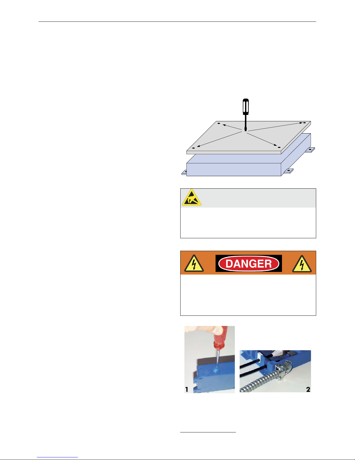
Das UPS darf nur von autorisiertem und umfassend
geschultem Personal montiert werden!
In Kanada sind besonders die Klauseln 2.13.5.1 und
2.13.5.2 von CAN/CSA-B44-B89 zu beachten! In den
USA müssen alle Verbindungen, die 42 Volt oder mehr
erfordern, über Greenfield-Rohre und -Anschlussstücke
hergestellt werden. Trennen Sie die Stromversorgung
vor dem Öffnen des Kontrollers ab, um Stromschläge zu
verhindern. Entfernen Sie aus Sicherheitsgründen keine
befestigten Abdeckungen oder Sicherungskappen.
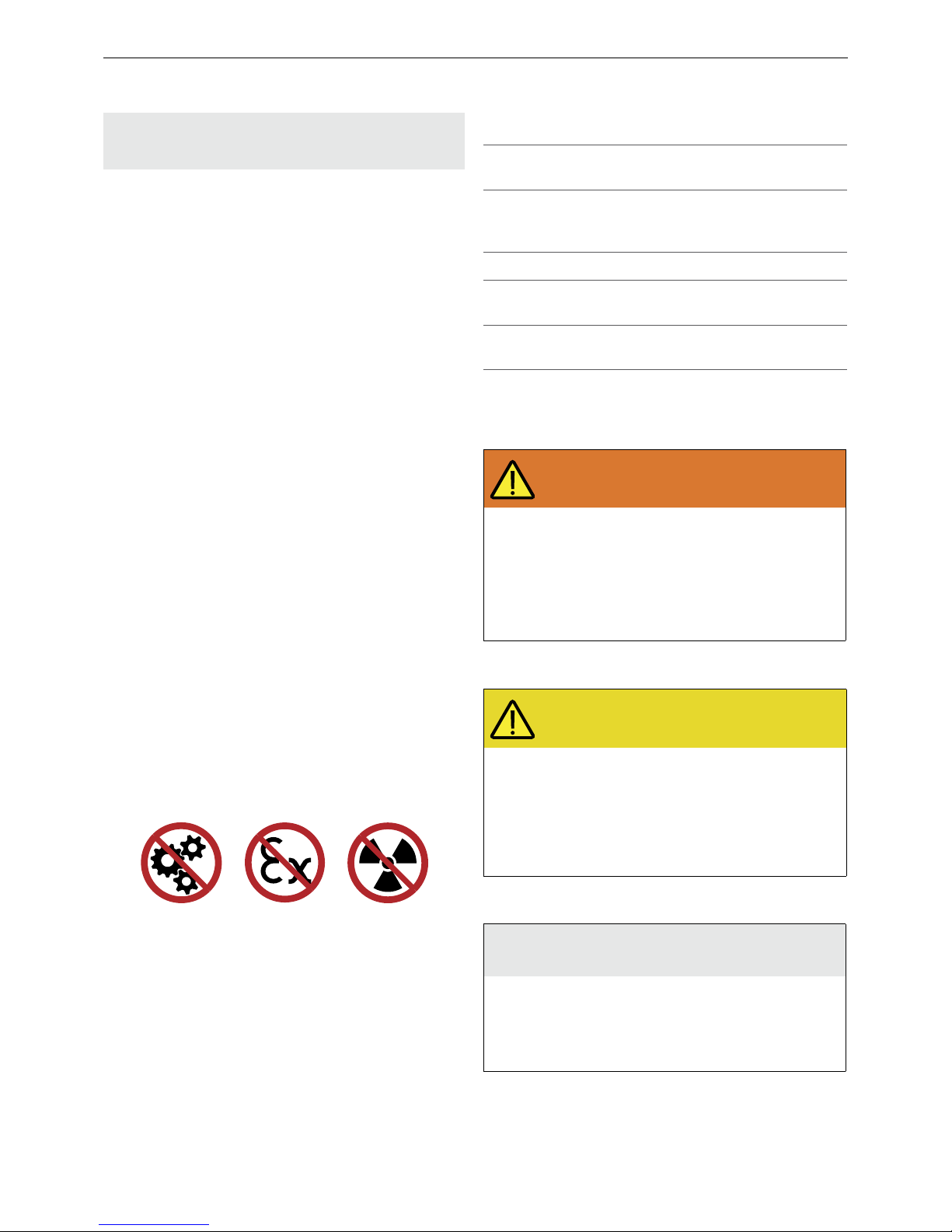
2.1 Nicht bestimmungsgemässe
Verwendung
Das UPS darf nicht eingesetzt werden:
• Zum Schutz von gefährlichen Maschinen
• Anlagen in explosiven Atmosphären
• Anlagen in radioaktiven Atmosphären
Für Anwendungen dieser Art dürfen nur spezielle, dafür
zugelassene Sicherheitsvorrichtungen eingesetzt werden.
Andernfalls kann dies zu schweren Verletzungen,
Todesfällen oder Sachschäden führen!
3. Symbole und
Sicherheitshinweise
3.1 Warnhinweiskategorien
Warnung vor schwerwiegenden Gesundheits-
gefahren
WARNUNG
Schwerwiegende Gesundheits-
gefahren
Enthält wichtige Informationen zur sicheren
Nutzung des Sensors. Nichtbeachten dieser
Warnungen kann zu schweren Verletzungen
oder zum Tod führen.
Handlungsaufforderungen nach drei-
eckigen Pfeilen befolgen
Die Sicherheitshinweise in Kapitel 2 dieser
Anleitung beachten
Hinweis auf mögliche Gesundheitsgefahren
VORSICHT
Mögliche Gesundheitsgefahren
Weist auf wesentliche Informationen zum
sicheren Gebrauch des Sensors hin.
Nichtbeachten dieser Hinweise kann zu
Verletzungen führen.
Handlungsaufforderungen nach drei-
eckigen Pfeilen befolgen
Die Sicherheitshinweise in Kapitel 2 dieser
Anleitung beachten
Hinweis auf Sachschäden
HINWEIS
Gefahr von Sachschäden
Nichtbeachten dieser Hinweise kann zu
Schäden am Sensor, der Türsteuerung und/
oder anderen Einrichtungen führen.
Handlungsaufforderungen nach drei-
eckigen Pfeilen befolgen
Symbol Bedeutung
Einzelne Handlungsaufforderung ohne
bestimmt Reihenfolge
1.
2.
3.
Handlungsaufforderung in einer
bestimmten Reihenfolge
• Aufzählungspunkt, Reihenfolge ist
unerheblich
àVerweis auf ein Kapitel, eine
Abbildung oder Tabelle in diesem
Dokument
Wichtig Wichtige Informationen zur richtigen
Nutzung des Sensors