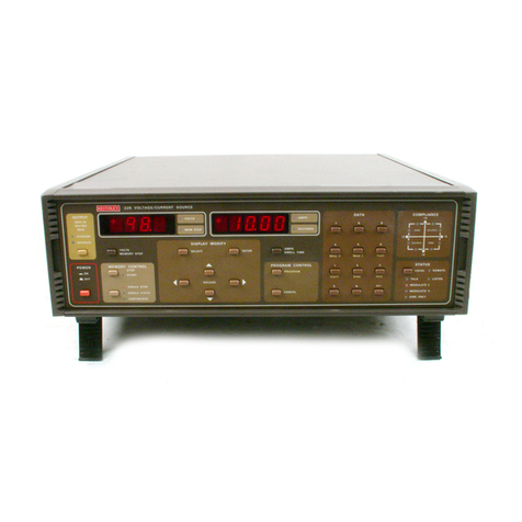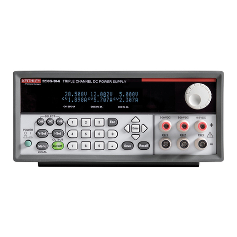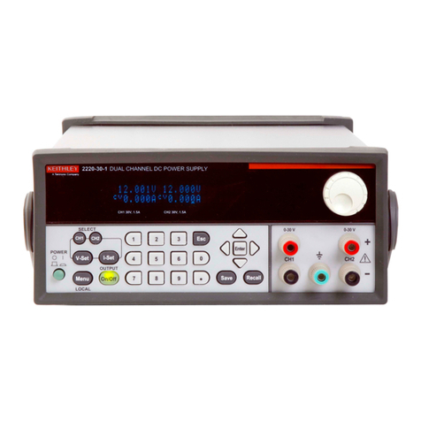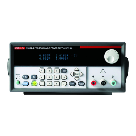
WARRANTY
Keithley Instruments, Inc. warrants this product to be free from defects in material and workmanship for a period of 1year from date of
shipment.
Keithley Instruments, Inc. warrants the following items for 90 days from the date of shipment: probes, cables, rechargeable batteries,
diskettes, and documentation.
During the warranty period, we will, at our option, either repair or replace any product that proves to be defective.
To exercise this warranty, write or call your local Keithley representative, or contact Keithley headquarters in Cleveland, Ohio. You will
be given prompt assistance and return instructions. Send the product, transportation prepaid, to the indicated service facility. Repairs
will be made and the product returned, transportation prepaid. Repaired or replaced products are warranted for the balance of the origi-
nal warranty period, or at least 90 days.
LIMITATION OF WARRANTY
This warranty does not apply to defects resulting from product modification without Keithley’s express written consent, or misuse of
any product or part. This warranty also does not apply to fuses, software, non-rechargeable batteries, damage from battery leakage, or
problems arising from normal wear or failure to follow instructions.
THIS WARRANTY IS IN LIEU OF ALL OTHER WARRANTIES, EXPRESSED OR IMPLIED, INCLUDING ANY IMPLIED
WARRANTY OF MERCHANTABILITY OR FITNESS FOR A PARTICULAR USE. THE REMEDIES PROVIDED HEREIN ARE
BUYER’S SOLE AND EXCLUSIVE REMEDIES.
NEITHER KEITHLEY INSTRUMENTS, INC. NOR ANY OF ITS EMPLOYEES SHALL BE LIABLE FOR ANY DIRECT, INDI-
RECT, SPECIAL, INCIDENTAL OR CONSEQUENTIAL DAMAGES ARISING OUT OF THE USE OF ITS INSTRUMENTS AND
SOFTWARE EVEN IF KEITHLEY INSTRUMENTS, INC., HAS BEEN ADVISED IN ADVANCE OF THE POSSIBILITY OF
SUCH DAMAGES. SUCH EXCLUDED DAMAGES SHALL INCLUDE, BUT ARE NOT LIMITED TO: COSTS OF REMOVAL
AND INSTALLATION, LOSSES SUSTAINED AS THE RESULT OF INJURY TO ANY PERSON, OR DAMAGE TO PROPERTY.
Test Instrumentation Group, Keithley Instruments, Inc. l 28775 Aurora Road l Cleveland,Ohio 44139 l (216) 248-0400 *Fax: (216) 248-6168
CHINA: Keithley Instruments, Inc. *Holiday InnLido l Office Building 4&4Cl Beijing, China, ICOO l 8610-436-2871/2860 l 8610-436-2871
FRANCE: Keithley Instruments SARL *3All&edes Gamys l B.P.60 l 91122 PalaiseauC&dex*01-60-11-51-55~ Fax: 01-60-H-77-26
GERMANY. Keithley Instruments GmbH l Landsberge.rStr.65.82110 Gennering 0089-849307-O l Fax: 089-84930759
GREAT BRITAINz Keitbley Instruments, Ltd. l The Minsterl 58 PortmanRoad l Reading, Be&shire RG30 IEA l 01734-575666 l Fax: 01734-596469
ITALY: Keithley Instruments SRL l Vialc S. Gimignano 38 l 20146 hfilano. 02-48303008 l Fax: 0248302274
JAPAN: Keithley Instruments Far East KK l Sumiyoshi 24 Bldg., Room 201 l 2-24-2 Sumiyoshi-cho *Naka-ku, Yokohama 231 l 81-45-201-2246 l Fax: 81-45-201-2247
NE-S: Keithley Instruments BV. Awlingen West49 l 4202 MS Gorinchem . Postbus559 l 4200 AN Gorinchem l 01830-35333 *Fax: 01830-30821
SWlTZERUNDz Keithley Instruments SA* Kriesbachstrasse4 l 8600 Diibendorf *01-821-9444 l Fax: 01-820-3081
Artisan Technology Group - Quality Instrumentation ... Guaranteed | (888) 88-SOURCE | www.artisantg.com
