AP&T AP-AY151X Specification sheet

AP-AY151X/251X
Product Instruction Manual
Digital display intelligent AC power supply
Shangh ai Anping Static Technology Co., Ltd.
Website : www.ap-static.com
Address : 3/F,Building 27,No.69,Guiqing Road,Shanghai,China
Tel : +86-21-64517676
Fax : +86-21-64517673

AP-AY151X/251X digital display intelligent AC power supply is one of the high-voltage power supply series products for static eliminator produced
by Anping Company (AP&T) which is designed for controlling the static electricity on the surface of the target to achieve the purpose of electrostatic
safety protection for the discharged object. It is a digital display intelligent AC power supply with alarm function which is a dedicated configuration
power supply for Anping's AC ion bar products.
Product Features
1. With energy storage components to ensure stable output power.
2. The fan can dissipate heat and ozone in real time to extend the service life of the power supply.
3. High voltage and low current working.
4. Pluggable interface which is easy to operate and install.
5. With voltage fault alarm function and the panel display shows the equipment working voltage in real time.
6. The power supply with communication function can be monitored online on the adapting software.
7. With short-circuit protection function, it will automatically cut off the power supply when the device is short-circuited.
Product details and dimensions
Model AP-AY1517/2517 AP-AY1515/2515
Input voltage AC220V/50Hz or AC110V/60Hz
Output voltage AC7000V(No load)AC5600V(No load)
Power < 20W
Status indicator
Working temperature - 10℃—+ 50℃
Working humidity <75%RH
Net weight 3050g
Dimensions L*W*H:136*170*120
1
2
3
4
5
110
136
120
1-High voltage output
2-Grounding stud
3-Status indicator
4-High voltage display
digital tube
5-RJ45 interface
6-Three-in-one power
socket
7-Fan
6
7
170
40
R3
40
Product Description
Specifications
Red light——High voltage fault alarm
Blue light——cleaning,Blue light flashing——debugging
Green light——normal work
Status indicator
High voltage output
High voltage output
Grounding stud
Grounding stud
High voltage display digital tube
RJ45 interface
Three-in-one power socket

Network port cable function information
1、2+24VDC
3 RS485+B
4 RS485+A
5 GND
6 GND
7
8
9 Metal shield PE
The output wiring diagrams of pins 7 and 8 are as follows:
Button function instructions
Unlock, press +/- to switch the display of working address, cleaning cycle, working
environment temperature/humidity, alarm threshold
&77 +ĺ
$/7+ĺ
&$/ĺ 2.
'LVSOD\LQIRUPDWLRQGHVFULSWLRQ
7000 Display the real-time high-voltage output value of the high-voltage power supply:7000VAC
A00 Display the working address of the high-voltage power supply :00
E15 Display the cleaning cycle of the matching ion bar:15(Unit:day)
C19 Display the internal working environment temperature of the high-voltage power supply:19℃
H19 Display the internal working environment humidity of the high-voltage power supply:19%RH
1000
Display the alarm threshold of the high-voltage power supply: 1000VAC
&$/ĺ
ĺ
Installation Guide
1. Insert the national standard power cord plug into the mains socket.
2. Insert the high-voltage connector of the static elimination device into the high-voltage output socket of the power supply and connect its ground
terminal to the ground stud of the high-voltage power supply.
3. The switch indicator and status indicator light on(Green light on when working normally) and the display showing the working voltage value
normally indicates the power supply working normally when turn on the power switch.
4. One end of the communication network cable should be inserted into the RJ45 communication socket on the front panel of the power supply,
and the other end should be connected to a monitoring terminal or connected to a PC through a USB-485 converter If communication is
required. The port wiring and panel descriptions are as follows:
Orange/White-orange
Blue
White-blue
Green
White-green
Brown
White-brown
HVAL:High voltage alarm
ACT:Power on indication
Clean:Cleaning indication
5、The cleaning cycle of the high-voltage power supply can be set by the remote control, as shown in the table below:
Unlock
Run / Pause
Parameter display
Adjust cleaning cycle
Adjust alarm threshold
Confirm
Reset
Unlock before adjusting operating parameters
Device starts running when power is on. Press "STOP" to standby and no high voltage
output. Press "RUN" again and the device will start working.
Press CTTH first, then press +/- to increase or decrease the cleaning cycle (Default 30
days, adjustment range is 1-60 days)
Press ALTH first, then press +/- to increase or decrease the high voltage alarm threshold
(Default 1000V, adjustment range is 500-2000V)
Press CAL first, then press OK to confirm after adjusting the output parameter
5HVHW,3UHVV&$/ ILUVW,WKHQSUHVV
(eg:High voltage from 7000VAC 1000VAttenuation 6000VAC alarm)
HV Alarm signal:Normal--always open、Abnormal--always close Power signal :Normal--always close
cleaning signal:Clean--always open

1. Please read the instruction manual carefully before installing and using this equipment.
2. The working input power of the power box must be reliably connected to the grounding wire of the electrical power supply cable and the
grounding resistance should be less than 4 ohm; Otherwise, it is easy to cause abnormal or even damage of ion bar and high voltage power supply.
3. Do not use this equipment in environment where humidity is > 70%.
4. It is strictly forbidden to use this equipment in flammable and explosive environments.
5. Unauthorized disassembly of the product is strictly prohibited, internal maintenance and repair must be performed by professionals.
6. It is strictly forbidden to touch liquid during use, otherwise an abnormality may occur and cause electric shock or fire.
7. Power must be turned off during inspecting or replacing the product, otherwise it may cause electric shock or fire.
8. The product is specially designed for eliminating static electricity. It is strictly forbidden to use it for other purposes. Any abnormal use may cause
machine failure, electric shock, fire and other accidents.
9. Please check the input voltage before powering on the product. Any power supply that does not meet the specifications will cause damage to the
product.
10.Please check the product power cord regularly and replace it immediately if it is damaged. Otherwise it is easy to cause problems such as electric
leakage and abnormal operation.
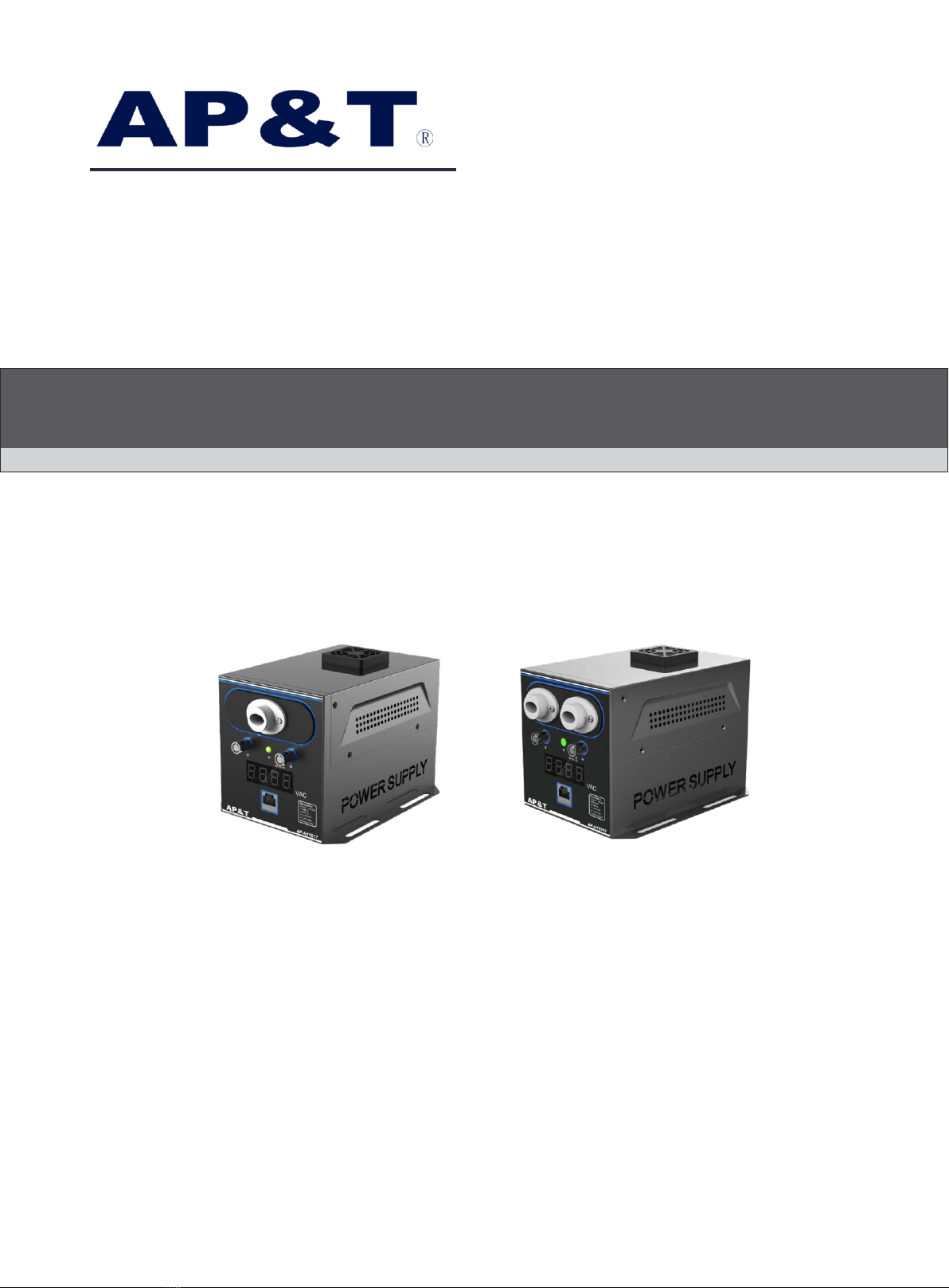
1. AP-AY151X/251X digital display intelligent AC power supply has undergone rigorous testing and aging treatment before ex-work. Its
performance has completely reached the relevant indicators marked in the usage instruction.
2. AP&T makes a commitment to the customer that any defective parts inspected by AP&T will be repaired or replaced free of charge within one
year from the date of purchase. However, this commitment does not apply to:
a. The device is incorrectly used or installed.
b. Damage caused by negligence or accident during use.
c. Modified, disassembled or repaired by other service departments not authorized by Anping Company.
3. AP&T shall not be liable for any incorrect use of the products except for repair or replacement of parts as specified above.
NO
1
2
3
4
5
Maintenance
It should be stopped and repaired by professional maintenance personnel when the red switch work indicator on the back panel of the high voltage
power supply is off, or the status indicator on the front panel is red or off, or the display is abnormal. It can be used only after the electrical
performance indicators are normal.
Problems Reasons Solutions
The switch indicator on the
back panel is off
Poor contact of the power cable Check whether the power cable is in good condition and
securely connected
No power supply Check the on-site power supply lines
The status indicator on the
front panel is red
No power supply from high voltage transformer Return to factory for maintenance
High voltage transformer is damaged Return to factory for maintenance
High-voltage components is damaged Return to factory for maintenance
The panel indicator light is blue Cleaning indication Ion bar and power supply cleaning maintenance
The display is abnormal or fuzzy Abnormal discharge
Check the connection between the high-voltage plug of the ion
bar high-voltage cable and the power supply high-voltage socket
to confirm that the plug is inserted in place
The product is smoky or burnt
The high-voltage transformer or high-voltage
components are damaged or the insulation of
the discharge socket is damaged Return to factory for maintenance
Safety warning Warning
After-sales service
Packaging accessories
1、Manual
2、Certificate of conformity
3、National standard power cord
4、Remote control
5、Network cables, converters and matching software are optional if communication function is required
This manual suits for next models
1
Other AP&T Power Supply manuals

AP&T
AP&T AP-AY450 Series Specification sheet

AP&T
AP&T AP-AY1505 User manual

AP&T
AP&T AP-DC7201 User manual

AP&T
AP&T AP-AC2455 Series User manual

AP&T
AP&T AP-AB1216 User manual

AP&T
AP&T AP-AY1506 User manual

AP&T
AP&T AP-AY1502 User manual

AP&T
AP&T AP-AB1216 User manual

AP&T
AP&T AP-DY7221 Specification sheet

AP&T
AP&T AP-DY6702 User manual
Popular Power Supply manuals by other brands

Artesyn
Artesyn RTM-ATCA-749X quick start guide

Puls
Puls Dimension Q-Series manual

Agilent Technologies
Agilent Technologies 6611C Service manual

Fike
Fike EPACO PSU E10-0067 Installation and operation instruction

Honeywell
Honeywell HPR12DC416UL Product installation document

Arc Machines
Arc Machines 501 Operation manual