CELSION QUBE Basic Plus User manual

1
User Manual
QUBE®- Safety Case
for Batteries
As of: September 2023
Serial number:
to be lled in by customer
Example: QUBE®Premium

2

3
Table of contents
1. INTENDED PURPOSE 5
1.1 Intended use 5
1.2 Warranty 5
2. FEATURES 5
2.1 Technical specications 5
2.2 Measurements 6
2.3 Versions 7
2.4 Scope of delivery 7
3. SAFETY INSTRUCTIONS 7
3.1 Icons 7
4.1 General information 8
3.2 Further information 7
4. TRANSPORT, INSTALLATION & COMMISSIONING 8
4.5 Electrical installations (optional) 14
4.2 Transport 8
4.3 Storage and environmental conditions 9
4.4 Installation 9
4.4.1 General information 9
4.4.2 Line-up options (height x width) (optional) 9
4.4.3 Line-up vertically (optional) 10
4.4.4 Line-up horizontally (optional) 12
5.1 Card reader with keyboard (QUBE®Premium) 17
4.5.1 Connection of the potential-free signaling contact (optional) 14
4.5.2 Connection of the Wiegand interface (Premium / optional) 14
4.6 System commissioning of extinguishing system 15
5. SETTINGS 17
5.1.1 Set Administrator Password (QUBE®Premium) 17
5.1.2 Set authentication mode (QUBE®Premium) 17
5.1.3 Add / change /delete user (QUBE®Premium) 18
5.1.4 Opening the closure unit (QUBE®Premium) 19
5.1.5 Set unlock duration (QUBE®Premium) 19
5.1.6 Dene reactions to incorrect operation (QUBE®Premium) 19
4.4.3.1 Screw connections between the QUBE® safety case 10
4.4.3.2 Back wall mounting / anti-tilt (optional) 11
4.4.4.1 Screw connections between the QUBE® safety case 12

4
6.3 Visual inspection 20
7.1 General indications 23
6.4 Extinguishing medium tank 20
6.4.1 General notes 20
6.4.2 Preparation for maintenance instructions / Important information for
mainenance service 20
6.5 Smoke detector (optional) 22
6.5.1 Functional test (optional) 22
6.5.2 Resetting the smoke detector (optional) 22
6.5.3 Replacing the smoke detector (optional) 23
6.6 Replacement of connecting house 23
6.7 Functional check of extinguishing system 23
7. POSSIBLE ERRORS 23
7.2 Optical and acoustic signals (QUBE®Premium) 23
7.2.1 QUBE® LED indicator lights (QUBE®Premium) 23
7.2.2 Card reader with keyboard (QUBE®Premium) 24
7.3 Leaks 24
7.3.1 Liquid leakage at the lower door rebate 24
7.3.2 Leakage on the extinguishing medium tank / connecting house 24
7.4 Action recommendation when the extinguishing system is triggered 24
7.4.1 Functional principle in case of an event 24
7.4.2 Characteristics 24
7.4.3 Incident 25
7.4.4 Measures after deletion process 25
7.5 No voltage on the socket (charger doesn not charge) /
Card reader without function (QUBE®Premium) /
LED-indicator lights without funktion (QUBE®Premium) 25
8. MANUFACTURING DECLARATION 26
9. DISCLAIMER OF LIABILITY 26
10. CUSTOMER RESPONSIBILITY 26
11. APPENDIX 27
11.1 Visual inspection checklist 27
6. MAINTENANCE & SERVICING 19
6.1 General information 19
6.2 Maintenance schedule 19

5
1. Intended Purpose
1.1 Intended use
The QUBE® safety case is a tested re protection housing with a re resistance duration of at least
90 minutes, tested in accordance with DIN EN 1363-1 in the sense of EI90 (<->io), designed for the
passive and active storage of primary and secondary batteries with lithium compounds (hereinafter
referred to as batteries).
For safety and approval reasons (CE), the unauthorized conversion and/or modication of the product is
not permitted. Any use other than that described above is not permitted and may result in damage to
the product. In addition, this is associated with hazards such as short circuit, electric shock, re, etc.
Consider the following information when using the QUBE® safety case:
• the safety instructions in this manual
• the chapter "Properties" in this manual (see point 2)
• a careful and professional commissioning and maintenance of the assembly (see points 4 & 6)
• Proper handling of the batteries in accordance with the manufacturer's instructions and the local re-
gulations
1.2 Warranty
The warranty for this product is based on the contractual agreements, our oers, as well as in addition to
our General Terms and Conditions.
We do not assume any liability for material and personal damage caused by improper use or non-compli-
ance with the safety instructions. The warranty/guarantee shall be void in such cases.
Please note that operating and/or connection errors are beyond our control. We also assume no liability
for any resulting damage.
2. Features
2.1 Technical specications
Technical specications
Input voltage 110-240 V / 50-60 Hz
Current consumption max. (without load) 250 mA / 230 V/AC
350 mA / 115 V/AC
Number of protective contact sockets 3
Connected load max. 3450 W
Fluse 15 A
Stored battery energy max. 625 W/h per Lithium-ion-battery (plastic housing)
Signaling contact (potential-free)
optional 1 changeover contact
Signaling contact rating max. (resistive load)
optional 30 W, 50 VA
(2 A, 60 V/DC, 120 V/AC)
Wiegand interface
Premium / optional Wiegand 26 Bit
Number of users per card reader
Premium Up to 2000
Protection class Class I
IP-Code
IK-Code
Fire test DIN EN 1363 i<->o
Fire resistance 90 min
Operating temperature 10 °C to 40 °C
External dimensions (HxWxD) 600 x 600*x 640 mm
Internal dimensions (HxWxD) 343 x 458 x 458 mm
Weight approx. 98 Kg*
* without extinguishing medium tank

6
2.2 Measurements
Front View from the right
View from above – Door opening angle 90° View from above – Door opening angle 180°
Fiew from the left
Example: QUBE®Premium
If the door opening angle exceeds
180°, the product can be damaged!

7
2.3 Versions
versions
features Basic Plus Premium
automated extinguishing system incl.
pottom pan ● ●
extinguishing medium tank ● ●
triple socket ● ●
ventilation system in the charging area ● ●
closure with protection from external access cylinder lock electromechanical
shutter
authentication of the closure
key RFID card / PIN
2-factor authentication possible
keyed alike
(standard)
keyed dier
(option) MF 13,56 MHz
(standard)
EM 125 kHz
(option)
LED indicator lights °●
automatic door locking in case of re °●
potential-free signal contact °/● °/●
tablet holder incl. charging stations °/● °/●
thermal runaway protection
(in case of external re) °/● °/●
EN 54-7 smoke detector °/● °/●
Wiegand 26 interface ° °/●
2.4 Scope of delivery
1 QUBE® safety case
1 Bottom pan
1 Extinguishing medium tank
2 Plug-in seals
2 cable ties
1 sealing ring
1 Hose Adaptor
2 Keys (Base Plus) / 2 RFID cards (Premium)
3. Safety Instructions
3.1 Icons
Important information, that must be observed, is marked with the exclamation
mark in this operating manual.
3.2 Further information
• Observe the temperature conditions (according to the technical data) at
the installation site. Failure to do so may result in damage to the battery
and/or unintentional erasure.
• Safe storage of the batteries is only provided by an extinguishing system
that has been put into operation, a plugged-in power plug and a closed
housing door! Keep the door always closed!
• The re protection system only meets the requirements of re resistance and
protection against the eects of a thermal runaway when closed.
● included in the scope of delivery | ° not included in the scope of delivery | °/● optional

8
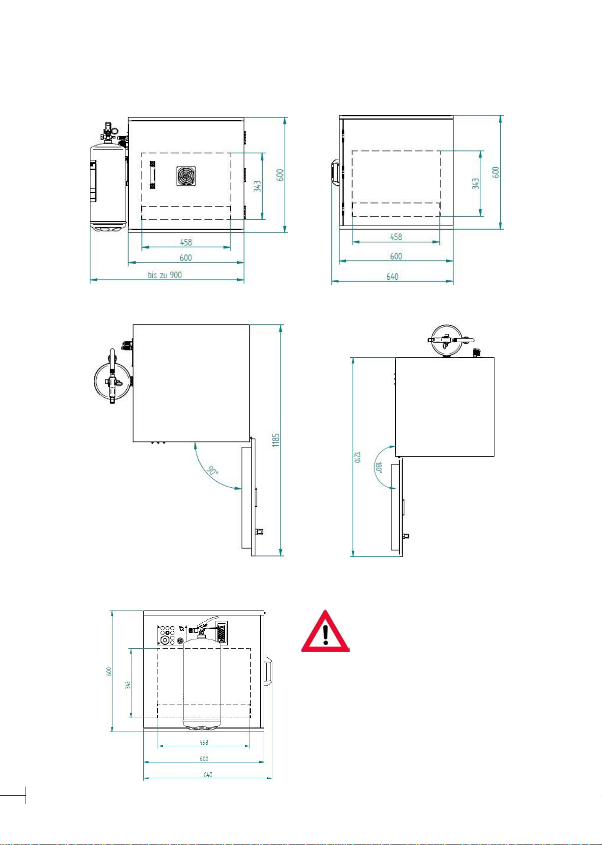
• The door of the QUBE®safety case may be opened up to a maximum of 180°.
• For the best possible protection, the batteries that are to be stored / charged must be
placed as at as possible in the bottom pan.
• Protect the QUBE®safety case from splashing water with increased pressure or permanent
uid exposure. Fluid exposure with regard to the power plug and the socket strip is to be
completely avoided!
• Do not expose to direct UV or sunlight. Do not operate heaters in the immediate vicinity.
• Do not operate the QUBE® safety case in an environment where ammable gases, vapors
or dust exist.
• Protect the QUBE® safety case from strong vibrations and other mechanical inuences, as
it can be damaged by the eects.
• Keep the QUBE®safety case away from children. This is not a toy!
• For installation, operation and maintenance, the applicable occupational safety, accident
prevention, DIN/VDE regulations must be observed on their own responsibility.
• Obviously damaged lithium batteries should not be stored inside buildings.
• The operating and instruction manual of the QUBE®safety case must be constantly availa-
ble at the place of use.
• Do not store any highly inammable materials / re loads in the immediate vicinity of the
QUBE®safety case
• Do not operate the QUBE®safety case in poorly ventilated rooms (especially not inside
poorly ventilated living spaces)
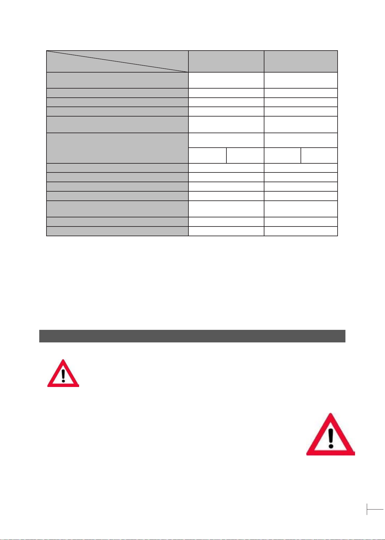
• The maximum energy (in Wh) of the stored batteries must be observed (see 2.1 technical
specications)
4. Transport, Installation & Commissioning
4.1 General information
The QUBE® safety case must be checked immediately upon delivery and any recognisable defects must
be immediately noted on the accompanying document / consignment note from the freight forwarder. De-
fects have to be reported to the seller or the Celsion Brandschutzsysteme GmbH in writing (no later than
5 working days after delivery).
The transfer of risk is upon delivery. Defects that may have arisen as a result of further transport of the
systems are excluded from subsequent performance.
In case of doubt, the device is not to be used!
Please note that a switch (e.g. circuit breaker or power switch) must be assigned to this device as a dis-
connection device. This applies both to an integration into the electrical installation of the building, as
well as to the connection with the standard power plug.
Care should be taken to ensure that this switch is properly installed and easily accessible to the user.
Any specications regarding the electrical protection of the regulations applicable on site must be taken
into account.
The safety case must not be operated with the aid of a socket strip.
Improper installation can damage both the product and all other connected devices.
4.2 Transport
Improper transport (hard impacts, transport without air suspension, repeated reloading, unilateral loading
during installation, etc.) can have an impact on the re protection function (damage to the re protection
panels or their connections).
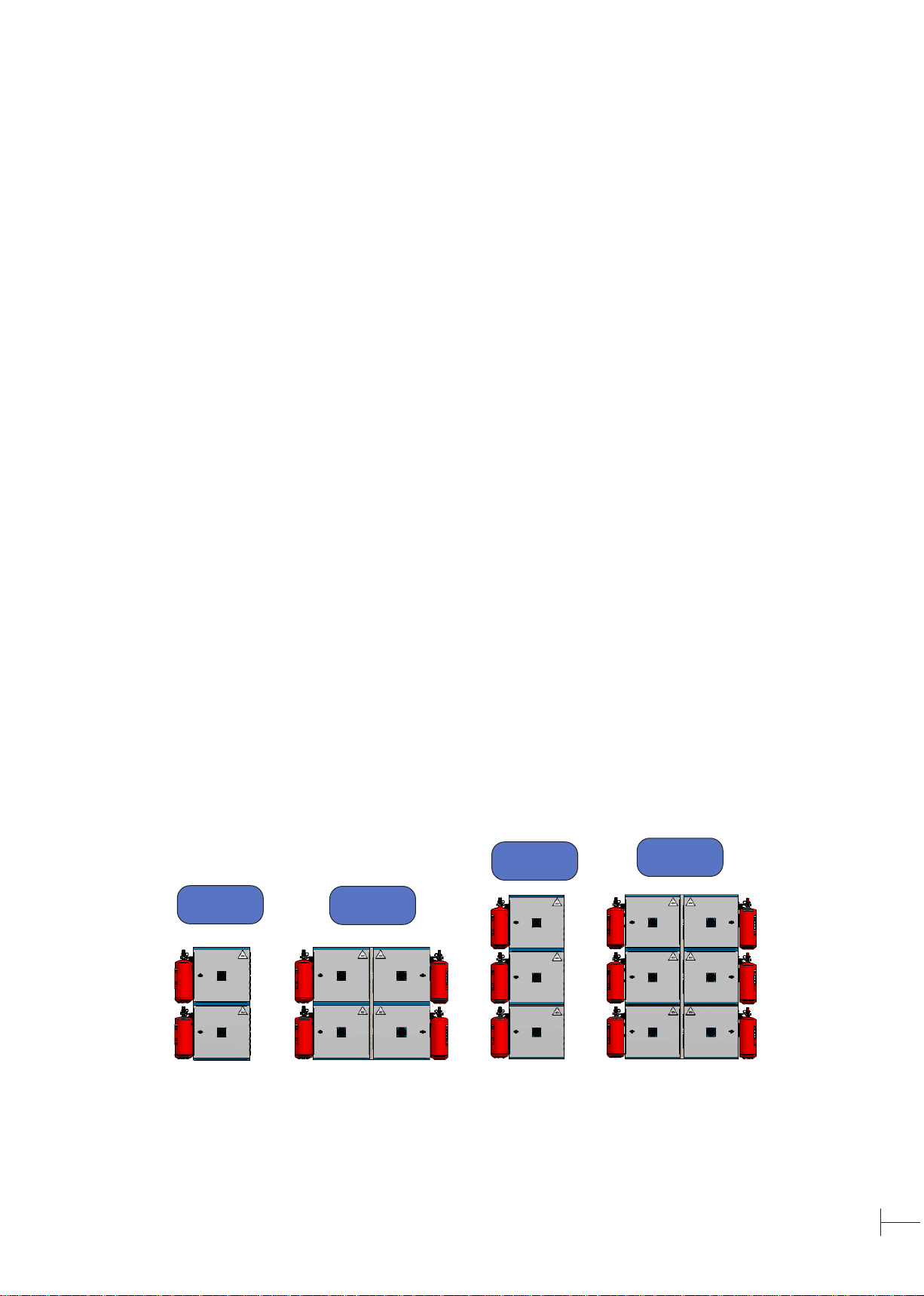
If a relocation of the system is necessary, it may only take place uniformly, over the entire surface and
with the door closed.
For safety and approval reasons (CE), the safety case may only be transported
or moved separately from the extinguishing medium tank. Transport with an
attached extinguishing medium tank is not permitted!

9
4.3 Storage and environmental conditions
In order to enable the full functionality and a long service life of our products, we ask you to observe and
adhere to the following points during intermediate storage, installation and assembly:
• Do not store or set up outdoors
• Protect against moisture, rain, splash water and weather conditions
• Do not store/build below 10 °C/above 40 °C
• Do not store / build in rooms with a humidity of more than 50% at 40 °C. Higher humidity values are
permitted at lower temperatures.
• Do not expose to frost
• Leave safety case on transport pallet during intermediate storage
• Do not stack (a transport-related stacking can take place in the production plant and does not aect
the function of the systems)
• Do not burden (a transport-related stacking takes place in the production plant and does not aect
the function of the systems)
• Store and set up only on rm, level ground
• During assembly by authorized employees or partner companies of Celsion Brandschutzsysteme
GmbH, it is essential to comply with the instructions and specications of the installers
• On-site installation conditions must be observed
4.4 Installation
4.4.1 General information
1. The housing must be placed at on a suciently load-bearing surface
2. In case of smooth surfaces, a non-slip mat may need to be laid underneath
3. Check the position of the housing by means of a spirit level and align it if necessary
The door must not grind on the body when opening and closing.
The gap dimensions between the door and the body must be uniform.
The version-dependent closure must be able to lock properly.
An impairment of the stability of the system when the doors are open is to be expected if the
system has not been screwed to the structure.
4.4.2 Line-up options (height x width)
2x1 2x2
3x1 3x2
If you require a larger line-up than 3x2, please contact our customer service.
Example: QUBE®Basis Plus

10
4.4.3 Line-up vertically (optional)
4.4.3.1 Screw connections between the QUBE®safety cases
1. Align the QUBE®safety cases ush
at the corners
required materials
2. Remove each of the right and left screws
from the lower strip of the enclosure
opening of the upper safety case
3. Pre-drill through the existing screw holes
with a 4 mm drill bit, 60 mm deep
4. Remove the existing drill dust from the
hole and screw the new fasteners
(2 pieces 4,5 x 60 mm wood construction
screws) into the drill holes
Do not
overtighten!
Repeat steps 1-4 for another line-up.

11
4.4.3.2 Back wall mounting / anti-tilt (optional)
required materials
Due to the reduced stability, a tilt protection is man-
datory for each vertical line-up. The pre-drilled xing
holes in the rear panel must be provided at the ma-
nufacturer’s work and can only be made subsequently
by our authorised service personnel. We therefore
recommend specifying this in advance in the orde-
ring process.
1. Check the accessories for completeness
• Pre-drilled xing holes in the back
wall of the enclosure
2. Align the safety case vertically on
the wall and drill through the pre-
drilled fastening holes in the rear
panel. Do not drill into/through the
rear panel of the enclosure!
Caution: Danger of breakage!
3. The exact drilling depth depends on the dowel
length and is to be determined as follows:
• Required drilling depth =
dowel length (135 mm) – panel thicknes
(68 mm) + 10 mm
• minimum anchoring depth of the provided
dowels: 50 mm
• drilling diameter: 10 mm
4. Remove the drill dust from the drill hole.
Hammer in the dowel with the screw up to the
drill hole opening (push-through installation),
tighten the screw with a suitable wrench/screw
driver/cordless screwdriver until the screw head
is ush with the dowel that has been driven in.
Do not overtighten!
Do not countersink the screw head into the
material!
Wall surfaces must be level and plumb. Unevenness on the wall surface (gaps/sinkings/curva-
tures) of more than 5.0 mm must be evened out with the re protection putty (Crystal Cel) so
that the properties of re protection are guaranteed.

12
4.4.4 Line-up horizontally (optional)
4.4.4.1 Screw connections between the QUBE®safety cases
required materials
1. Align the two QUBE® safety cases and
the 41 mm re protection panel ush with
the rear panel
2. Remove the upper and lower screw from the right
strip of the left safety case as well as the upper
and lower screw from the left strip of the right
safety case

13
3. Pre-drill the existing xing holes with a 4mm drill
bit, 60 mm deep
4. Remove the existing drill dust from the hole and
screw the fasteners (2 x 2 pieces 4.5 x 60 mm
wood construction screws) into the drilled holes
Since horizontal line-up is usually requested in combination with vertical line-up, point
4.4.3 must also be considered in the next step.
Do not
overtighten!

14
4.5 Electrical installations (optional)
The electrical installation may only be carried out by a qualied specialist with electrotechnical training or
further training who is familiar with the corresponding regulations and possible dangers.
Improper installation can damage both the product and all other connected devices.
CAUTION! Any work on the safety case must only be carried out in the
de-energized state! If the power plug is available - be sure to remove it from
the socket! Observe the following ve safety rules!
4.5.1 Connection of the potential-free signaling contact (optional)
If the forwarding of an error message to a higher-level control center or re alarm center is desired, this
must already be taken into account in the ordering process. A subsequent installation is only possible by
our authorised service personnel.
For the closing contact, please use the labelled wires 1 (Co) & 3 (NO) and for the opening contact, the
labelled wires 1 (CO) & 2 (NC) of the control line. The maximum connected load can be found under point
2 "Technical specications". Please note that you may need to secure this contact
with a connected load in order to avoid damage to the relay contact, the sheath line, etc.
The contact that remains unobstructed must be clamped potential-free!
4.5.2 Connection of the Wiegand interface (Premium / optional)
The interface for integration into the building access management system is only possible in combination
with the QUBE® Premium variant and must be provided at the factory. A subsequent installation is only
possible by our authorised service personnel.
When connecting, it must be ensured that the numbered conductor 1 is
provided for the data line 1 (Data1), the conductor 2 is provided for the
data line 2 (Data2) and the conductor 3 is provided for the ground line (GND).
2
1
3
Data1 1
Data2 2
Data3 3

15
4.6 System commissioning of extinguishing system
1. Screw hose adapter including sealing
ring into extinguishing medium tank and
tighten (30 Nm)
2. Lightly oil the thread and
cone of the hose adapter, as
well as the thread and sealing
cone of the connecting hose
3. Screw the union nut of the connec-
ting hose onto the hose adapter
until the force increases noticeably.
Then tighten with a key with
max. ¼ rotation.
4. Hang extinguishing medium
tank in wall bracket

16
5. Attach the extinguishing medium
tank to the intended retaining
bracket with a cable tie
6. Pulling the safety pin of the lever tting
7. Actuate lever armature
---> Extinguishing system is now
under pressure!
8. Insert the locking pin in the pressurized
position of the lever armature

17
9. Lock the locking pin using the
plug-in seal
10. Insert the power plug into
the socket
Before use, it is advisable to subject the safety case to a detailed visual inspection.
Please use our checklist in Appendix A.
5. Settings
5.1 Card reader with keyboard (QUBE®Premium)
5.1.1 Set Administration Password (QUBE®Premium)
Enable programming mode *Administrator code #
999999 is the factory administrator code
Exit Programming Mode *
Changing the administrator codes 0New code #New code #
The administrator code must be 6 to 8 digits
Note:
In order to perform the following programming, the administrator must be logged in using the
administrator code.
5.1.2 Set authentication mode (QUBE®Premium)
Setting the operation mode:
Cards
Cards and PIN
Cards or PIN
30# Authentication by card only
31# Authentication by card and PIN
32# Authentication by card or PIN (default)

18
5.1.3 Add / change / delete user (QUBE®Premium)
Adding aPIN-user 1User ID number #PIN #
The ID number is any number between 1 and 2000.
The PIN is any number between 0000 and 9999 (except
1234). Users can be added continuously without leaving
the programming mode.
Deleting a PIN-user 2User ID number #
Users can be added continuously without leaving the
programming mode.
Changing the PIN of a PIN-user
(This must be implemented outside the
programming mode’) *ID number #Old PIN #New PIN #New PIN #
Adding a Card-user (Method 1) This is the fastest way
to add cards, user ID numbers are generated automati-
cally.
1Read card #
Cards can be added continuously without leaving the
programming mode.
Adding a Card-user (Method 2) This alternative method
allows cards to be assigned specic IDs. Only one card
can be assigned to a user
1ID number #Read card #
Cards can be added continuously without leaving the
programming mode.
Adding a Card-user (Method 3) The card number is the
last 8 digits printed on the card.
Users can be added continuously without leaving the
programming mode.
1Card number #
Users can be added continuously without leaving the
programming mode.
Adding a Card-user (Method 4) This alternative method
allows cards to be assigned specic IDs. Only one card
can be assigned to a user
1ID Number #Card number #
Users can be added continuously without leaving the
programming mode.
Deleting a Card-user per card 2Read card #
Users can be deleted continuously without leaving the
programming mode
Deleting a Card-user per user ID This option can be
used if a user has lost their card 2User ID #
Deleting a Card-user per card number.
This option can be used if the user wants to make a
change but the card has been lost
2Card number #
Users can be deleted continuously without leaving the
programming mode
Adding acard and aPIN in card- and PIN-mode (31#)
Adding a Card- and a PIN-user.
The PIN is any number between 0000 and 9999 (except
1234)
Add the card the same way as for a Card-user
Press * to exit the programming mode.
Then assign a PIN to the card as follows:
*Read card 1234 #PIN #PIN #
Changing the PIN in card- and PIN-mode (Method 1)
Note: done outside of programming mode so that the
user can make the change himself *Read card Old PIN #New PIN #New PIN #
Changing the PIN in card- and PIN-mode (Method 2)
Note: done outside of programming mode so that the
user can make the change himself *ID number #Old PIN #New PIN #New PIN #

19
To delete acard- and PIN-user, only the card needs to
be deleted
2User ID #
Adding a Card-user in map mode (30#)
Adding and deletig a Card-user The procedure is the same as in adding and deleting in
mode 32#
Delete all users
Delete all users
Attention! Can not be reverted
20000 #
5.1.4 Opening the closure unit (QUBE®Premium)
As a PIN-user PIN #
As a Card-user Read card
As a Card- and PIN-user Read card PIN #
5.1.5 Set unlock duration (QUBE®Premium)
Setting the activation duration *Administrator code #40~99 #*
0-99 for setting the activation time between 0-99 s
5.1.6 Denereactionstoincorrectoperation(QUBE®Premium)
Response to erroneous operation
If 10 unauthorized cards are read within 10 minutes or 10 incorrect PINs are entered, the keypad is deactivated for
10 minutes or the acoustic signal is activated for 10 minutes, depending on the option selected below.
Normal operation: No deactivation of the keypad 70# (factory setting)
Keyboard panel deactivation 71#
Activate acoustic signal 72#
6. Mainenance & Servicing
6.1 General information
The safety inspections, the small-scale repair services of the re protection systems and the mandatory
biannual visual inspection must be carried out by participants of the Celsion maintenance training or em-
ployees of Celsion Fire Protection Systems GmbH on the basis of the required expertise and due diligence
requirements.
For external cleaning of the system, common, mild household cleaners can be used.
Only original spare parts may be used for maintenance and repair work.
Remove all chargers and batteries from the QUBE®safety case for the time of maintenance &
servicing.
6.2 Maintenance schedule
Maintenance point Time interval Performed by
visual inspection using the checklist (Appendix A) every 6 months Owner / Celsion authorised customer
service
Functional check EN 54-7 smoke detector (if avai-
lable) every 12 months Attendee maintenance training /Celsion
authorised customer service
Maintenance of extinguishing medium tank at least every 2
years * by Celsion authorised customer service

20
Replacement of connecting hose and sealing ring every 6 years by Celsion authorised customer service
Function control extinguishing system every 6 years by Celsion authorised customer service
Replacement of EN 54-7 smoke detector
(if available) every 8 years Attendee maintenance training /Celsion
authorised customer service
Extinguishing medium tank replacement every 20 years User
* Depending on the maintenance schedule of the extinguishing medium tank, the legal requirements on site and the maintenance certicate on the
extinguishing medium tank.
6.3 Visual inspection
A regular check is important in order to be able to detect any damage or wear at an early stage and must
therefore be carried out at least twice a year.
Please use our checklist in Appendix A.
6.4 Extinguishing medium tank
6.4.1 General notes
Opening and maintenance measures only by experts (by customer services specically
authorised by Celsion).
The maintenance instructions of the company Celsion, which are valid in each case,
apply to the maintenance.
An exchange of the extinguishing medium tank is only possible in consultation with Celsion
Brandschutzsysteme GmbH.
The use of unauthorized extinguishing medium tank may result in a malfunction of the safety
case!
6.4.2 Preparation for maintenance instructions / Important information for the maintenance service
To start with the standardised maintenance measures, proceed as follows:
2. Remove the lead seal and
pull the securing pin out of
the squeeze-grip valve
1. Remove the main plug from
the QUBE® safety case
Additional notes on the maintenance schedule:
In commercial use, an inspection as a transportable or movable electrical equipment is required.
With regular and careful maintenance, a operating life of more than 30 years is possible.
This manual suits for next models
1
Table of contents