Ziegler RI 10 User manual

IC 15030858
www.ziegler-instruments.com 1|10
© Ziegler Instruments Order No. -E1.R0-921022-2-2014-ENRI 10 User Manual
RI 10
Analog - Digital Insulation Tester ( User Manual)
Analogue Meters With Moving - Iron Movement

RI 10
MW
50V
100V
250V
500V1KV
V
7
0 100 200 300
TEST
ON
OFF
ESC
STORE
V MW
W
fused
600V CAT II / 300V CAT III
6
5
4
3
2
1
DC
V
ON
600V
8
15
V
W WM
ON
910 11
12
13
14
16
17
18
19
0 100 200 300
DC AC
MIN MAX
ZERO
www.ziegler-instruments.com 2|10
(1)Liquid Crystal Display (10) Symbols for displaying the
(2)On/Off push button selected functions
(3)Push button (11) Display for selected function
(4)Push button (12) Display for the unit of
(5)TEST Push button measured quantity
(6)Function selector switch (13) Over range Indication
(7)Terminal sockets (14) Pointer for Analog indication
(8)Symbol for (15) Scale for Analog Indication
“CONTINUOUSLY ON” (16) Activated stop watch Indicator
(9)Digital display with indication (17) Zero adjust indicator
of decimal point and polarity (18) Low battery indicator
(19) Buzzer indication
295
0.999

www.ziegler-instruments.com 3|10
1) Safety Features and Precautions
You have selected an instrument which provides you with a high level of
safety.
The RI 10 Analog-Digital Insulation Tester is manufactured in
compliance with safety regulations IEC 61010-1/EN 61010-1/VDE 0413
part 1. When used for its intended purpose. safety of the operator, as well
as that of the instrument, is assured. In case of incorrect use or careless
handling, the safety of both user and instrument is not assured.
To maintain the safe and proper condition of the instr ment and to ensure
its safe operation, it is absolutely necessary to carefully and completely
read these operating instructions before using the instrument. These
instructions must be followed in all respects.
Observe the following safety precautions :
* The instrument must be operated only by persons who
understand the danger of shock hazards and know how to
apply safety precautions. Shock hazards exist anywhere,
where voltages of more than 30 V may occur.
* Do not work alone in shock hazardous environment while carrying
out measurement.
* The maximum allowable voltage between any terminal sockets
and earth is equal to 600 V for voltage and 1000V for Insulation
resistance measurement.
* Verify that the test leads are in good condition, e.g. no cracked
insulation, no open circuits in the leads or connectors.
* Measurements under moist ambient conditions are not permitted.
* Do not exceed the permissible overload limits of the measuring
ranges. Limit values can be found in the table in “12. Specification”.
Safety Precautions for Insulation Resistance
Measurement
* The circuit under test be switched off, de-energized,must
isolated Insulation or Continuity tests are made.before
* The button be pressed while connecting theTEST must not
test leads or while changing ranges.
* The Voltage warning while in STOP WATCHdoes not function
mode or in MENU structure.
* During an Insulation test, connections be touched.must not
* After insulation tests, capacitive circuits be allowedmust
to discharge disconnecting test leads.before
* Test leads and crocodile clips in good condition,must be
clean and with no broken or cracked insulation.
u
Earth
Continuous, doubled or
reinforced insulation
Warning concerning a point of danger
(Attention : observe documentation)
Meaning of symbols on the instrument
CE EU Confirmity mark
Repair, Parts Replacement and Calibration
After opening the instrument, live parts may be exposed.Therefore, the
instrument must be disconnected from the measuring circuit prior to
opening its case for repair, replacement of parts or calibration. If repair or
calibration cannot be avoided, unless the instrument is open and live, the
work must be performed by a qualified person, who understands the
danger involved.
Faults and Extraordinary Stress
When it is realized that the safe operation is no longer possible, take the
instrument out of service and secure it against accidental use.
Safe operation is no longer possible -
nWhen the instrument shows obvious sign of damage,
nWhen the instrument no longer functions correctly,
nAfter a prolonged storage under adverse conditions,
nDue to severe stress due to transportation.
2 Initial Start-Up
Battery
Fit the instrument with the six 1.5V cells (IEC LR6 type) provided along
with the instrument.
Before you use the instrument for the first time or after storage refer
to section '' 3. Maintenance Battery ''
Switching the Instrument ON
Instrument can be switched ON :
1. By pressing the ON/OFF button.
2. By changing the function selector switch from current position
to desired function.
Switch-on is acknowledged by a sound signal.The instrument is now
ready for operation.
Attention !
Before opening disconnect the instrument from the
measuring circuit and ensure high voltage is not available
on leads.
Automatic turn-off
Your instrument turn off automatically, if any of the keys or the function
selector switch have not been activated for about 10 minutes in
insulation resistance range and 5 minutes in other ranges.
How to prevent automatic TURN-OFF
In order to prevent automatic “TURN-OFF” select “CONTINUOUSLY
ON” mode For this push TEST push button and the “ON-OFF”
pushbutton together when switching ON the instrument.
The symbol is displayed on the LCD to indicate this
“CONTINUOUSLY ON” mode.
Switching the Instrument Off
Press “ON/OFF” pushbutton for a longer time.
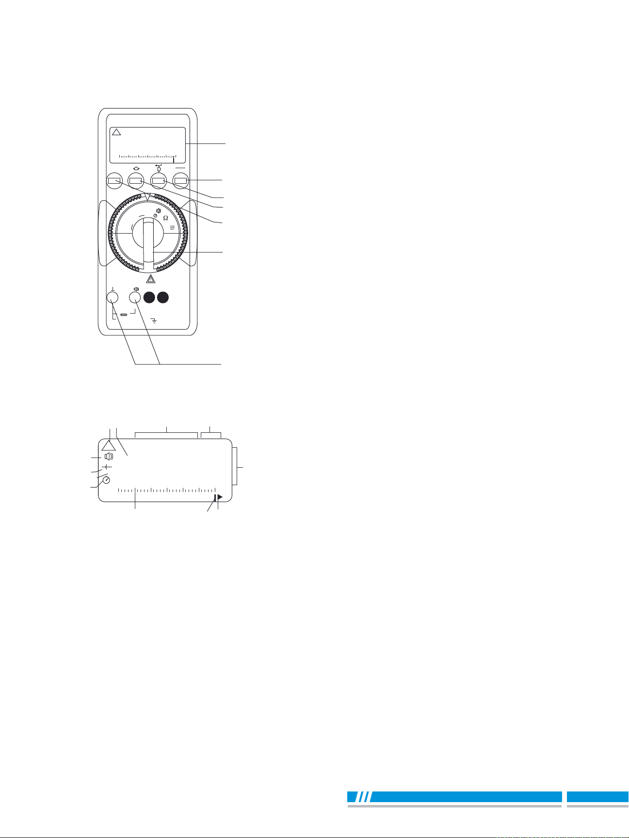
3. Selecting Measuring Functions
The desired measuring function is selected with the Function selector
switch.
4. Liquid Crystal Display
4.1 Digital Display
The digital display shows the measurement value and decimal point.The
selected measuring unit and function are displayed.
4.2 Analog Display
The analog indication gives the dynamic performance of a moving coil
mechanism.This is especially advantageous for the observation of
measurement value fluctuations and for calibration procedures.
ON

Insulation Resistance Measurement
Note
During Insulation resistance measurement the symbol
flashes as long as the high voltage is present at the terminals
ON
RI 10
R
50V
100V
250V
500V1KV
V
MW
www.ziegler-instruments.com 4|10
5. Insulation Resistance Measurement (M )W
5.1. Preparation for measurement
·Select the required "Test Voltage (50V/100V/250V/500V/1000V)"
by changing the "Function Selector Switch".
·Connect the test probes firmly to the circuit under test.
Note !
Insulation resistance can only be measured at voltage free
object. Hence the circuit under test must be switched off,
de-energized and isolated before carrying out any insulation
resistance measurement.
When measuring high-ohmic insulation resistance do not
touch the measurement cables.
If an interference voltage > 25V is present within the
system, insulation resistance measurement is disabled.
The instrument defaults to the default voltmeter and
displays the value of the interference voltage on the LCD.
Also the instrument indicates this additionally by an
acoustic signal.
HIGH-VOLTAGE
Do not touch the conductive ends of the test probes
after insulation resistance measurement has been
activated at the instrument.
A current with a value of 2 mA (limited by the instrument)
may flow over your body, and although this is not life
endangering, the electric shock is distinctly perceptible.
If you are taking a measurement at a capacitive device under test, for
example a cable, it may be charged with as much as
1000V, depending upon the selected nominal voltage.Touching the
device under test after measurement may be life endangering in such
cases!
5.2 Insulation resistance measurement
The instrument provides flexibility for both manual and
continuous (for a pre-selectable time) insulation - resistance
measurement.
5.2.1 Manual Insulation resistance measurement :
In manual Insulation resistance measurement, Press and hold "TEST"
key until the display has stabilized. Insulation resistance measurement is
ended when the yellow TEST key is released. Instrument will continue to
show the last reading for few seconds even after releasing the "TEST
key".
Note !
The instrument's batteries are depleted during insulation
resistance measurement. Only press and hold the TEST key
as long as it is necessary to take the reading in the manual
measurement mode. Continuous measurement as described
below should be performed, if absolutely necessary.
210

5.2.2 Continuous measurement for a pre-selectable time :
In normal course, the insulation test terminates when the test key
is released and the measured insulation resistance value remains
on display for few seconds after the test key is released.
With the Pre-selectable measurement time feature, the
insulation test continues for the pre-determined time.
Pre-selectable time : 10 sec-5 min
Refer to the “11. Menu structure” section for how to set the value for pre-
selectable time. Once the time is set it is applicable to all the 5 ranges of
Insulation measurement.
nSelect the required value of the time for which the test is
to be carried out.
nBriefly Press the TEST key. The insulation resistance
test carries on for the time interval selected.
nThe test terminates automatically after the selected time
has elapsed.
nThe display then flashes the value of measurement at
the end until the Key is pressed.
5.3 Conclusion of measurement and discharging
After the measurement has been completed, any residual voltage is
displayed which may be caused by capacitive circuits. Contact with the
device under test must be maintained.The reduction in voltage can be
directly observed at the LCD.
Do not disconnect the device under test until voltage has dropped
below 25 volts !!
Note : Automatic discharge !
The capacitive circuits are automatically discharged when
TEST button is released following an insulation resistance test.
This auto discharge facility eliminates the need for the user to
discharge the circuit under test manually.
Additional features available in Insulation measurement ranges.
1. Pre-selectable limit checks (Go/Nogo option)
2. Storing the measured resistance value
3. Minimum and Maximum value “MIN/MAX” storage
www.ziegler-instruments.com 5|10
6 Additional Features
6.1 Pre-selectable limit checks (Go/No-Go option)
An acoustic signal can be generated when the measured value of
resistance falls below an adjustable noGo value.
A separate noGo value can be set for each range of insulation
resistance measurement as well as for Ohms, Continuity ranges.
Refer to the “11. Menu structure” section for how to set the value
for the noGo value.
6.2 Storing the measured resistance value
lTo store the value of resistance press “STORE” key when the
resistance measurement is in progress. This will store the
resistance measured at the instant the key is pressed.
lThis way maximum 10 readings per range can be stored.
th
lAfter 10 values are stored for the selected range the 11 value
when stored will over-write the first value i.e. at any given point
of time only ten readings per range can be stored.
lThe readings are stored in a volatile memory.Therefore when the
instrument is switched off, the readings are lost.
Recalling the stored values
The stored values can be recalled and viewed in the menu
structure.
Refer to the “11.Menu Structure” section for how to view the
stored value.
6.3 Minimum value and Maximum value “MIN/MAX” storage
facility (for all measuring ranges)
With the MIN/MAX function, you can hold the minimum and the
maximum measured value which was applied to the input of the
instrument after activating MIN/MAX.The most important application is
determination of minimum and the maximum value for long term
monitoring of measured quantities.
The function MIN/MAX can be activated in all measuring ranges.
MIN/MAX does not influence analog indication, you can still read the
actual measured value.
Apply the measured quantity to instrument prior to activating MIN/MAX
function.
The MIN/MAX function is switched off when.
1. Key is pressed for approximately for 1 Sec. OR
2. Then function selector switch is operated OR
3. When the instrument is turned OFF and ON again
Function
MIN/MAX
Measured Value
MIN and MAX
Meter reaction
Display
Measured value DigitalMIN/MAX
Sound
signal
1. Activate
and store
2. Store
and display
3. Return
to 1.
Reset
short
short
short
short
long
Stored
Stored continued
in background
new MIN and MAX
values are displayed
Same as 1.
Stored values are
not cleared
Cleared
Actual measured value
Stored MIN value
Stored MAX value
Same as 1.
Cleared
MIN/MAX
flash
MIN flash
MAX flash
Same as 1.
Cleared
1x
1x
1x
1x
2x

Continuity Test
-
00
RI 10
0
MW
50V
100V
250V
500V1KV
V
+
-
RI
10
0L
MW
50V
100V
250V
500V1KV
V
+
www.ziegler-instruments.com 6|10
7. Continuity Testing and Resistance Measurement
Attention !
Be absolutely certain that the device under test is
voltage-free.
7.1 Continuity Testing
* Verify that device under test is electrically dead.
* Set the function selector switch to “ ” position.
* If required null lead resistance by doing Zero adjustment below.
* Connect the device under test as shown in diagram.
* The measured resistance value will be displayed on the display.
* The instrument generates a continuous sound signal if
the measured resistance value is less than the pre-setted
“GoNoGO” value. Default value is 5W
Refer to the “11. Menu structure” section for how to set the value
for the limit value.
7.2 Low Ohm Measurement ( )W
* Verify that device under test is electrically dead.
* Set the function selector switch to “ ” position.W
* If required null lead resistance by doing zero adjustment below.
* Connect the device under test as shown in diagram
* The measured resistance value will be displayed on the display.
* The instrument generates a continuous sound signal if the
measured resistance value is less than the pre-setted
“GoNoGO” value. Default value is 0W
Refer to the “11. Menu structure” section for how to set the
value for the limit value.
7.3 Zero adjustment
When measuring very low resistance values, you can eliminate
resistance of leads and contact resistance by zero adjustment.
* Connect the test leads to instrument and connect the free ends of
the leads to one another.
* Wait for reading to stabilize.
* Briefly press the “TEST” push button. The instrument
acknowledges zero adjustment by a sound signal and
the LCD shows “0.00” (+1digit) and the symbol “ZERO” (17) is
displayed.The resistance measured at the instant the push button
is pressed is used as reference value (0-9.99 ). It is automaticallyW
deducted from the values measured thereafter.
* Zero adjustment can be cleared.
ØBy pressing the “TEST” button once again.
ØBy switching the instrument off.
Also zero adjustment is cleared when Auto shutOFF operates.
Additional features available in Ohm and Continuity ranges.
1. Pre-selectable limit checks (Go/Nogo option)
2. Storing the measured resistance value.
3. Minimum and Maximum value “MIN/MAX” storage.

8. Voltage Measurement (V AC/DC)
You can use this instrument for voltage measurement from 25V to 600V
AC or DC.
* Keep the function selector switch to “V ” position and
apply the input.
* The instrument automatically displays whether the input
is AC or DC along with the value of the external voltage.
* If the value of voltage is < 25V (AC or DC), the display
“025V” flashes. If the value of the voltage is > 600V (AC
or DC), a continuos acoustic signal is generated.
* When reverse DC is applied it displays “-dc”
Additional features available in Insulation measurement ranges.
1. Minium and Maximum value “MIN/MAX” storage
Voltage Measurement
9. Default Live Circuit Warning
When more than 25V (AC or DC) is applied to the terminals the
instrument defaults to voltmeter on all switch positions. In addition the
beeper will sound on all switch position (except the V position).
When external voltage>25 V is present, Insulation Ohm and Continuity
Tests are inhibited.
When external voltage <25 V is present, only the Insulation Tests are
available !!
Note : The default live circuit warning does not operate
(i) when in STOPWATCH mode.
(ii) when in MENU structure.
+(-)/~
-(+)/~
RI 10
MW
50V
100V
250V
500V1KV
V
www.ziegler-instruments.com 7|10
10 Stop Watch
This function allows you to measure elapsed time up to one hour.
To use stop-watch
1. Set the function selector switch to Continuity " " position.
2. “TEST” 00:00Press key.This will show the stopwatch from
3. RESETPress key at any time to the stopwatch.
4. START STOPPress key at any time to or the stopwatch.
5.To quit stopwatch and go back to basic display, Press key.“TEST”
11 Menu Structure
Structure of command menu for Insulation measurement :
Structure of command menu for Resistance & Continuity measurement
Menu structure Insu 10
Confirmation of selected
menu item via ENTER key
Select next menu item
in the flow direction
Go back to previous
level of menu
= Time
= Recall
= Minutes
= Seconds
= Value for noGo
= Strored value
mm
ss
nnnn
xxxx
Basic
Display
nnnn
mm:ss
xxxx
Basic
Display
nnnn
xxxx
xxxx
Esc
229

11.1 Description of Menu Items :
11.1.1 Setting the GoNoGo values :
(at all ranges except V )
Operating Order :
Basic noGo nnnn
Display
Setting : nnnn = noGo limit values in M (for Insulation ranges)W
nnnn = noGo limit values in (for Ohm and Continuity)W
1.Now scroll through different values using the key until
you come across required value.
2.To save this value press key. After saving, this will take
you to basic display.
3.To go back without saving press "ESC" key.This will take you to
main menu "noGo"
4.To go back to basic display from main menu "noGo" use "ESC" key.
11.1.2 Setting the Timer values
(Only at Insulation Resistance measurement ranges)
Operating Order :
Basic noGo ti mm:ss
display
Setting : mm= minutes, ss = seconds
1. Now scroll through different values using the key until
you come across required value.
2. To save this value press key. after saving, this will take
you to basic display.
3. To go back without saving press key.This will take you to"ESC"
main menu "ti"
4. To go back to basic display from main menu "ti" use key."ESC"
11.1.3 To see the stored values
(at all ranges except V )
Operating Order :
Basic noGo ti reCL nnnn
display
1. You can now see the first stored value.The scale pointer is used
to indicate the number (out of 10) of the displayed stored value.
2. Now you can view the successive stored value using the
key.The scale pointer also increments to indicate the number
(out of 10) of the displayed stored value.
3. To go back press key.This will take you to"ESC"
main menu "reCL"
4 To go back to basic display from main menu "reCL" use key."ESC"
Table for default values :
NoGo ti reCI
50V
100V
250V
500V
1000V
Ohm
Cont
V
1 MW
1 MW
5 MW
5 MW
500 MW
00 W
5W
---
00:00 (Manual)
---
---
---
0.00
0.00
0.00
0.00
0.00
0.00
0.00
---
www.ziegler-instruments.com 8|10
12. Specifications
Meas. Range Resolu- Accuracy Overload
function tion (..% of rdg value and
+ .. digit) duration
±
1) For insulation resistance range, 2) For low Ohms/continuity Ranges
* Terminal voltage on open * Open circuit voltage
circuit (DC) 5V ± 1V d.c.
- 0% to + 30% of rated voltage * Lead resistance
* Short circuit current < 2 mA compensation : 0 - 9.99 W
* Test current on load 1 mA at
minimum pass values of
insulation as specified
in VDE 0413 Part 1.
Reference Conditions :
0
Ambient Temp. +23C ± 2 K
Relative Humidity 45%...55%
Battery Voltage 8V ± 0.1V
Voltage Measurement AC (Sine), 50/60 Hz
Display
LCD display field (65 mm x 30 mm) with analog indication and Digital
display and with display of unit of measured quantity and functions
Analog
Display LCD scale with bar graph pointer
Scale Length 47 mm
Scaling 0...30 with 30 graduations
Over range Indication By triangle (13)
Digital
Display/Char. Height 7 segment digits/12mm
Number of Digits 3 digit for M andWW
4 digit for Stop watch
Over range Indication OL
Insulation
Resistance
1)
MW
U = 50 V,
N
100 V
0.01 M toW
0.99 MW
³W1.0 M to
9.9 MW
³W10 M to
99 MW
10 KW
()
0.01 MW
100 K toW
()
0.1MW
1 MW
± 3% ± 2
± 5% ± 2
± 30%
1200V rms,
10 sec
Insulation
Resistance
1)
MW
U = 250 V,
N
500 V,
1000 V
0.01 M toW
9.99 MW
³W10.0 M to
99.9 MW
³W100 M to
999 MW
10 KW
()
0.01 MW
100 K toW
()
0.1MW
1 MW
± 3% ± 2
± 5% ± 2
± 30%
1200V rms,
10 sec
2)
Low Ohms
W
0 9.99-W
³W- W10 99.9
0.01 atW
210 mA
0.1 W at
21 mA
± 3% ± 2
± 5% ± 2
1200V rms,
10 sec
2)
Continuity 0 9.99-W
³W- W10 99.9
0.01 atW
210 mA
0.1 W at
21 mA
± 3% ± 2
± 5% ± 2
1200V rms,
10 sec
V AC/DC 1V ± 2% ± 3 1200V rms,
10 sec
³-25V 450V
³-450V 600V
1V ± 3%

0.01MW0.1MW0.5MW1.0MW10MW100MW
Insulation Resistance
Output Voltage ( V )
1300
1200
1100
1000
900
800
700
600
500
400
300
200
100
1000 V Range
500 V Range
250 V Range
0.1MW0.05MW1MW10MW
Insulation Resistance
Output Voltage ( V )
130
120
110
100
90
80
70
60
50
40
30
20
10
100 V Range
50 V Range
10MW
Required min. Value of Insulation Resistance
(Limiting Value)
Minimum Display Value
5MW
2MW
1MW
0.5MW
0.2MW
0.2MW0.5MW1MW2MW5MW
www.ziegler-instruments.com 9|10
Power Supply
Battery 6 x 1.5V cells IEC LR6
(Nickel cadmium rechargeable cells
may be used)
Service Life Typically 2500 x 5 second operations with
alkaline manganese cells
Battery Test
Battery symbol “ ” appears on the LCD in either of below conditions :
1. Battery voltage is <5.4V. Battery replacement is necessary.
2. For a specific range depending on application
In either of the above condition, when the battery symbol is displayed, no
measurement can be done, and the battery symbol flashes.
Note : Battery cells should not be left in the instrument which may remain
unused for extended period of time.
Auto turn OFF
Instrument turns off automatically, if any of the keys or the function
selector switch have not been activated for about 10 minutes in
insulation resistance range and 5 minutes in other ranges.
Cable Set
2
Cu cross-sectional area 1 mm
End metallic parts should pass terminal 4 D 11
Technical data as per IEC 61010 / EN 61010-2-031 CATIII/1000V,
Air/creepage 16 mm.³
High Voltage test 7.4KV AC for 1 min.
Breaking force of the cable 36N, 1 min.³
Fuse 500 mA(F)/440V H.B.C. 10 kA min (32mmx6mm)
Electrical Safety
Protection Class II per IEC 61010-1/EN61010-1/VDE0411-1
Over voltage
Category II III
Nominal Voltage 600V 300V
Contamination degree 2 2
Test Voltage 3.7KV~per IEC 61010-1/EN61010-1
EMC
IEC/EN 61326 Electromagnetic Compatibility (EMC)
Environmental Conditions
0
Nominal Temp. Range 0.....35C
00
Operating Temp. -20C... + 40C (full range)
00
-20C... + 60C (up to 100 M )W
00
Storage Temp -25C...+65C
0
Relative Humidity 90% RH at 40C max.
0
Temperature Coefficient <0.1%perC
Mechanical Design
Protection Instrument :IP 50
For terminal socket : IP 20 according to
DIN VDE 0470 Part 1 / EN60529
Dimensions W x H x D
84mm x 195 mm x 35 mm
Weight 500 g including battery

13 Maintenance
Attention !
Disconnect the instrument from the measuring circuit before opening
the instrument to replace the battery or the fuse !
13.1 Battery
Before initial Start-up, or after long storage of your instrument, make
sure that no leakage has occurred at the instrument battery. Repeat this
inspection at regular intervals.
Battery symbol “ ” appears on the LCD in either of below conditions
:
1. Battery voltage is <5.4 V. Battery replacement is necessary.
2. For a specific range depending on application
In either of above condition when the battery symbol is displayed, no
measurement can be done, and the battery symbol flashes.
Replacing the Batteries
* Lay the instrument on to its face, loosen the two screws at the rare
panel and lift out the housing base, starting at the bottom (a).The
housing base and the housing top are held together with snap hooks
at the top of the front panel.
* Remove all the cells from the battery holder and replace them with
new ones.
* Important for reassembly : first lay the housing base into place such
as shown in diagram below. Push the housing base and housing
top together, first at the bottom front (a) and then at the top front (b).
* Retighten the housing base with the two screws.
* Please dispose of the used cells properly.
13.2 Fuses
Application of high energy pulse during Insulation resistance
measurement or application of voltage during Continuity and Ohm
measurement will blow the fuse. If the fuse blows, eliminate the cause of
the overload before placing the instrument back in to operation !
Fuse Testing
* Set the function selector switch to any insulation measurement range.
* Open circuit the test leads.
* Press the “Test” button until “OL” or “FUSE” appears on display.
If display = “OL” : Fuse is OK.
If display = “FUSE” : Fuse is blown and needs replacement.
Note : Once “FUSE” is displayed all the functions are inhibited.
Immediately switch the Instrument OFF and replace the fuse.
(b) (a)
www.ziegler-instruments.com 10 | 10
Replacement of Fuses
* Open the instrument as described under battery replacement.
* Remove the defective fuse and replace it with a new fuse.
* Make sure that the new fuse makes good contact.
Specification :
Current Rating : 500 mA / 500V-6.3 mm x 32 mm with a breaking capacity
of 10kA.
Recommended fuse manufacturer : Siba
Part No. : 70-065-63/0.5A
Be absolutely sure that only the specified fuses are used !
The use of a fuse with different triggering characteristics,
a different nominal current or a different breaking capacity
exposes the operator, the system and the measuring
instrument to danger. The use of repaired fuses or short-
circuiting of the fuse holder is prohibited.
13.3 Housing
No special maintenance is required for the housing. Excessive
contamination has an adverse effect on isolation and reduces input
resistance.The surface must be kept clean for this reason. Use a slightly
dampened cloth for cleaning. Oil free petrol is recommended for
cleaning. Avoid the use cleansers, abrasives or solvents.
ZIEGLER INSTRUMENTS
Schnepfenreuther Weg 6, D-90425 Nürnberg, Germany.
(+49)(911) 38 492 45
TEL.
(+49)(911) 32 26 212
FAX.
www.ziegler-instruments.com
E-MAIL
WEBSITE in
Germany
made
Table of contents
Popular Test Equipment manuals by other brands

Carl Roth
Carl Roth VioLab 50 Series instruction manual

Microtest
Microtest MICROSCANNER user guide

Radiodetection
Radiodetection SPX RD7100 user guide

ThermoFisher Scientific
ThermoFisher Scientific 146iQ instruction manual

PIE
PIE PIECAL 334Plus operating instructions

Sealey
Sealey AUTO SERVICE BT91/7C instructions