Central Hydraulics 94780 User manual

10000LBS2-POSTLIFT
Model 94780
INSTALLATION,OPERATION
&MAINTENANCE MANUAL
IMPORTANT: READTHISMANUALCOMPLETELYBEFORE
INSTALLINGorOPERATINGLIFT

GENERALSPECIFICATIONS
SeeFigure1
ARiseHeight (ScrewPads HighestPosition) 78 1/8 (1985mm)
BColumnHeight 151 3/16 (3840mm)
COverallWidth 131 1/2 (3340mm)
DDrive-thruClearance 99 3/8 (2524mm)
EFloortoOverheadSwitch144 (3660mm)
FShortArmReach 28 1/4 -41 3/8 (730-1050mm)
GLongArmReach 34 3/8 -55 1/8 (874-1400mm)
HScrewPadHeight 5 3/8 -7 1/4 (136-185mm)
KInsideofColumns 109 7/8 (2790mm)
*MaximumCapacity 10000LBS(4545kg)
CeilingHeightRequired 152 3/16 (3865mm)
Motor2HP,SinglePhase,60Hz,220V
*Liftcapacityratings arebasedonloads equallydistributedon allfourarms.
**Liftingandloweringspeedsmayvarydependingonweightofvehicle.
12’Min.ToNearestObstruction
Fig1a-GeneralSpecificationFig1b- Service BayLayout
VERTICALCLEARANCE
Checktheheightoftheareawheretheliftis tobeinstalled.Clearance shouldbecalculatedbasedon the
fullraisedheightofthelift.
Failurebypurchasertoprovideadequateclearancecouldresultin
unsatisfactorylift performance, propertydamage,orpersonalinjury.
FLOORING
Becertainyouhavetheproperconcretefloortoproperlyhandletheloadedlift.Floorshouldbein
generallygoodconditionwithnolargecracks, spallingordeterioration.
Minimumrequirementsforconcreteare4inchesminimumdepth,withsteelreinforcement,3500
PSI, curedfor28 days per localcommercialpractice.

Floorshouldbelevelwithin3/8inchovertheinstallationarea.Noanchorsshouldbeinstalledwithin8
inchesofanycrack,edge,orexpansion joint.Iftheseconditionscannotbemet,padscanbepouredto
accommodatethelift.
Checkwithlocalbuildinginspectorsand/orpermitsoffice foranyspecialinstructionsorapprovals
requiredforyourinstallation.
Failure bypurchasertoprovidetherecommended mounting
surfacecould resultinunsatisfactoryliftperformance, property
damage,orpersonalinjury.
AlwayswearANSIapproved safetygoggleswheninstallingand usingthisproduct.
ELECTRICALREQUIREMENTS
Forliftinstallationand operationforsinglephaseunits,it isnecessarytohaveadedicatedcircuit witha
25 ampcircuit breakerortimedelayfuse.
SAFETYNOTICESANDDECALS
Foryoursafety,and thesafetyofothers,readandunderstandall ofthesafetynoticesanddecals
includedhere.
READ ENTIREMANUALBEFOREASSEMBLING,INSTALLING,OPERATING,OR
SERVICINGTHISEQUIPMENT.
PROPERMAINTENANCEAND INSPECTIONISNECESSARY FORSAFE OPERATION.
DONOTOPERATEADAMAGEDLIFT.
Safetydecalssimilartothoseshownherearefound onaproperlyinstalledlift. Besurethatallsafety
decalshavebeencorrectlyinstalledon thePowerUnitreservoir.Verifythatall authorizedoperators
knowthelocationofthesedecals andfullyunderstandtheirmeaning. Replaceworn,faded, ordamaged
decalspromptly.

Donotattempttoraiseavehicleonthelift until thelifthasbeen
correctlyinstalledand adjustedas describedinthismanual.
RECEIVING
Theshipmentshouldbethoroughlyinspectedassoonasit isreceived.Thesignedbill ofladingis
acknowledgementbythecarrierofreceiptingoodconditionofshipmentcoveredbyourinvoice.
Ifanyofthegoodscalledforonthisbillofladingareshortedordamaged,donotacceptthemuntilthe
carriermakesanotationonthefreightbill oftheshortedordamagedgoods. Dothisforyourown
protection.
NOTIFYourcompanyATONCEifanyhiddenlossordamageis discoveredafterreceipt.
ComponentPackingList
DESCRIPTION QTY
DESCRIPTION QTY
PowerColumn Ass y 1 SynchronizerCable2
IdlerColumnAss y 1 HydraulicHosePack 1
PowerColumn Extension 1 PowerLockCover 1
IdlerColumnExtension 1 IdlerLockCover 1
OverheadAss y 1 HardwareBox1
RearArmAss y 2
FrontArmAss y 2
INSTALLATION
IMPORTANT:Alwayswearsafetyglasseswhileinstalling lift.
TOOLS (MINIMUMREQUIRED)
a. Banding Cutter
b. Tapemeasure,16ft
c. Chalkline
d. 4ftlevel
e. 10”adjustablewrench
f. Standardopenendwrenches7/16”-15/16"
g. Needlenosepliers
h. Hammerdrill
i. 2lbhammer
j. Torquewrench:150 footpoundsminimum
k. 12 ft. Stepladder
l. Anti-Seizelubricant(forarmpins)
LAYOUT
1. Layouttheservicebayaccordingtothearchitect s plansorownersinstructions(seeFig1b).Be
certainthattheproperconditionsexist.
2. Assemblecolumnextension tocolumnusingM12 30Hexbolt. Repeatforoppositecolumnand
extension.
3. UsingtheOverallWidth(C)asaguideline, chalktwoparallel(line1andline2)ontheconcrete
floorwithin1/8inchtolerance.
4. DeterminethelocationoftheColumnAss yon eitherchalklineandmarkthebaseplatedimension
OverallWidth(L).

Fig2 –FloorPlan
Besuretostaywithina1/4inchoveralltolerance. Thiswill eliminateany
difficultyinfinalassemblyorpossibleprematurechainwearor
misalignment.
Thechalklinelayoutis veryimportant.Ifitisnotfollowedaccurately
problems may ariseinfinalassemblyand operation.
5. Usingaliftingdevice, Erectbothcolumnassemblieswiththeinstallationlines.
ANCHORING
6. Theanchorboltsmustbeinstalledatleast8inches fromanycrack,edge,orexpansionjoint.
7. Useaconcretehammerdrillwithacarbidebit.Donotuseexcessivelywornbits orbitswhichhave
beenincorrectlysharpened.Acorebit maybenecessaryifanobstruction isencountered.
Neversubstitutewithshorter anchor.
8. Recheck “InsideofColumns”dimension,Fig1.Drilltheanchorholesusingthebaseplateasa
template. Drill throughthefloorifpossibleortoadepthof3.5inchesminimum.
9. Vacuumdustfromtheholeforproperholdingpower.
10. Shimbothcolumnstoplumbusingtheshimsprovided.DO NOTshimmorethan1/2"atany given
point.Usealevelnoless than24”inlengthtoplumbcolumns.
11. Assemblewasherandnuttoanchorwithnutjustbelowimpactsection ofbolt.Driveanchorinto
holeuntilnutandwashercontactbase.
12. Tightenpowercolumnanchorsandrecheckcolumn forplumb.Reshimifnecessary.Torqueto150
footpounds tosetanchors.
Neverremovetheliftbefore the columnsTightenedbytheanchorbolts.
OVERHEAD BEAM
13. Assembleoverheadass ytocolumnextensionusingM12 30Hexbolt.
14. Install OverheadLimitSwitchtoPowerColumn.
SYNCHRONIZERCABLES
15. Manuallyraisethecarriagesuntileachislocatedonthesecondlockposition.
16. RoutesynchronizingcablesusingFig3and attachendstocarriages joiningusingFig s4.
17. Adjustcabletensionbyadjustingeachcable sadjustmentnuts.Thecablesshouldbetightwithno
slack. Eachcableshouldbethesametension.Besureasyouaretightening thecablesthattheyhave
remainedinplaceoverthepulleys. Failuretodothis will resultindamagetothecable.

Fig3-CableRoutingFig4-Attaching
Cable
Priortooperationofliftrecheckequalizer cablesmakingsuretheyarenot
crossedorroutedimproperly.Besurethecableshaveremainedinplace
overthepulleys.
POWERUNIT& HYDRAULICHOSE
18. MountPowerUnittopowercolumnwithM8hexnuts, M8 20bolt.
19.Attachhydraulicelbowfittingtopowerunit.
20. IMPORTANT –Toinsureproperhosefittingsealwithoutdamagetothefittingfollowthis
procedureforeachhoseconnection: Screw flaredfittingonfingertight.Rotateflaredfitting11/2hex
flats(90deg.).Backtheflaredfittingoffonefullturn.Againtightenflaredfittingfingertight,then
rotateflaredfitting11/2hexflats(90deg).
21.Threadpowerunithydraulichoseintoelbowonpowerunit.RoutehydraulichosefromIdlercolumn
across OverheadtothePowerColumn.(Fig6)
22.OncethePowerUnitissecured,fillreservoirwith#10weight HYDRAULICOILONLY.Care
shouldbetakentokeepdirtorothercontaminationoutofoil.

Fig5-Hydraulics
Fig6
LOCKRELEASE
23. Install LockReleaseStudandKnob to PowerColumnLockusingoneM10 nut.
24.AttachMechanicalLock ReleaseCableAssemblytotwoColumn LockPawl(Fig 7).

Fig7Power ColumnLockIdlerColumnLock
ReleaseAssembly ReleaseAssembly
THELOCKRELEASECABLEADJUSTMENTISNOTCOMPLETEUNTILTHELIFTHAS
BEENLOWEREDAND “FINALADJUSTMENTS HAVEBEENMADE.
ARMINSTALLATION
25.Lubricatethearmpinorcarriagearmpinholewith “anti-seize”and installthearms. Insurethatthe
armrestraintgearsengageanddisengageproperly.Armrestraintsanybindingoccurs,insurethatthe
largegearmountedtothearmhasbeenfactoryinstalledtightagainstthearmpin.
ELECTRICAL
26.ConnecttheOverheadLimitSwitchCordtoPowerUnitasshowninnameplateon thePowerUnit.
27.ConnectPowerUnittosuitableelectricalsourceas showninnameplateonthePowerUnit.
28. IMPORTANT:AFTERWIRINGHASBEENCOMPLETED,TESTOPERATION OFPOWER
UNIT&OVERHEAD LIMITSWITCH. WHILE RAISING LIFT,OPERATEOVERHEAD
SHUTOFF BAR.POWERUNITMOTOR SHOULDSTOPWHENSHUTOFF BAR ISRAISED.
FINALADJUSTMENTS
29. Lowerthelifttothefloorandraisetheliftapproximatelyonefoot.
30. StartwithIdlersidefirst.Slowlyandcarefullyloosenthebleedplugontop ofthecylinderjust
enoughtoallowtheentrappedairtoescape. Repeatforpowerside.
31. Energizethepowerunitand raise6inches.Repeatpreviousstepuntilnoaircomesoutofcylinder.
32. Pressuretesthydraulicsystem.Energizepowerunit,raiselifttofullriseandcontinuetorunmotor
foradditional10seconds.(NOTE:pressurereliefwillmakeahighpitchsquealsoundforthese10
seconds.)Checkhydraulicsystemforleaks.
33. Energizepowerunit againfor10seconds. Withacleanrag,wipedownbothcylinderrods.If
lubricantisnotwipedcleanfromthecylinderrod, thecylinderwillappeartobeleaking.
34. Cyclelifttoinsurethatthelatchesoperatesimultaneously.Lowertheliftontothelocksandinsure
thatneitherlockwillwobble(itispossibleforthecarriagestoappeartoberestingon thelocks
whenactuallyonlyonecarriageisrestingonitslockandtheothercarriageisbeingsupportedby
thesynchronizingcable).

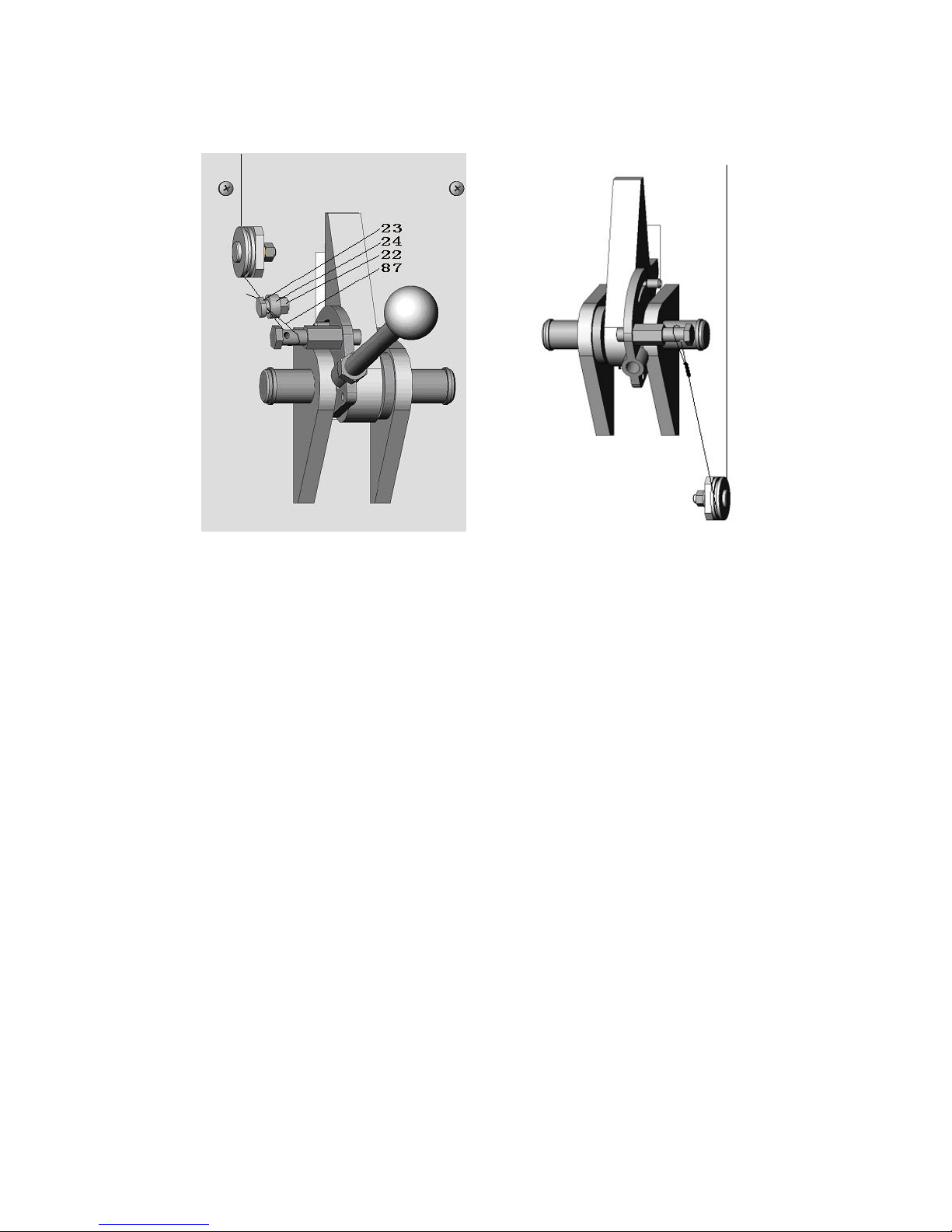
35. Lowerlifttothefloor.Pull andreleaselockreleasehandlewhilewatchingidlercolumnlock.
Adjustthreadedsleevecableadjusternutsuntilidlercolumn lockdisengagesandengagesfully.
Whenproperlyadjusted,theidlercolumnlockshouldjustcometorestagainstthebackofthe
column whenengagedandfullyoutagainstthetabwhendisengaged.
IMPORTANT:IFIDLERSIDELOCKPAWLDOESNOTFULLYDISENGAGE,DAMAGE
MAYRESULT TOIDLERSIDE CARRIAGEAND ORCABLESYNCHRONIZINGSYSTEM.
36. Tightenandtrimwireties.
37. Snaplockcoverovereachlockassembly.
OPERATIONPROCEDURE
SAFETYNOTICESANDDECALS
Thisproductisfurnishedwithgraphicsafetywarninglabels, whichare reproducedonpage3of
theseinstructions.Donotremoveordefacethesewarninglabels,orallowthemtoberemovedor
defaced.Foryoursafety, and thesafetyofothers, readand understandall ofthesafetynoticesand
decalsincluded.
OWNER/EMPLOYERRESPONSIBILITIES
Theowner/employershall makesurethatall liftoperatorsarequalifiedandtrainedinthesafeuseand
operationoftheliftinaccordancewiththemanufacturer soperatinginstructions.Theyalsoshall
displaytheliftmanufacturer soperatinginstructionsandmaintenancescheduleinaconspicuous
locationandarea,convenienttotheoperator.
Theowner/employershall establishprocedurestoperiodicallyinspectandmaintaintheliftin
accordancewiththeliftmanufacturer s suggestions. Theemployershall insurethattheliftinspectorand
maintenance personnelarequalifiedandthattheyareadequatelytrainedintheseprocedures.The
employershall maintaintheseperiodicinspectionandmaintenancerecords.
LIFTINGAVEHICLE
1) Insurethattheliftingarms areparked,outtofull drivethruposition.
2) Positionthevehicleintheservicebaysothatthevehicle scenterofgravityisonalinebetweenthe
twocolumns, andsothevehicleiscenteredbetweenthetwocolumns.
DONOTEXCEED2500POUNDSPERARM.
DONOTATTEMPTTOLIFTTHEVEHICLEWITHONLYTWOARMS,ASTHISWILL
VOIDTHEWARRANTY
INSURETHATTHEHIGHESTPOINTONTHEVEHICLEWILL CONTACTTHE
OVERHEADLIMIT SWITCHBAR
DONOTPLACETHEVEHICLE INTHE SERVICEBAYBACKWARDS.
3) Position thearmsandadapterssoallfourpadscontactthevehiclesimultaneously.
Thevehicleshouldremainlevelduringlifting.
4) Raisetheliftuntil allfourwheelsareofftheground.Testthestabilityofthevehiclebyattempting
torockthevehicle.Checkadaptersforsecurecontactwithvehicleliftpoints.Ifthevehicleseems
unstable,lowertheliftandreadjustthearms.If thevehicleisstable,raisethevehicletoaheighta
fewinchesabovethedesiredworkingheight.
5) Lowerthevehicleuntilthesafetylatchesonbothcolumnsengage.Thevehicleshouldremainlevel
whenbothlatchesareengaged.Ifonesideengagesandtheothercontinuestodescend,stop
loweringthevehicle, raiseitseveralinches, andtryagaintoengagebothlatches.
Always lower liftintolocks beforeenteringtheareabeneaththevehicle.
Alwaysusesafetystandswhenremovingorinstallingheavycomponents.

LOWERINGAVEHICLE
1) Insurethattheareaunderthevehicleisclearofpersonneland tools.
2) Raisethevehicleuntil both latchesarefree.
3) Disengagethelatchesbypulling down and holding thelockreleaselever.
4) Lowerthevehiclebydepressing thelowering valvehandle.
5) Continuetolowerthevehicleuntil thecarriagesstopagainstthebaseplate.Retracttheextension
arms, and park them.
MAINTENANCE
To avoidpersonalinjury, permit onlyqualified personnelto performmaintenanceon thisequipment.
Thefollowing maintenance pointsaresuggestionsforapreventivemaintenance program.Theactual
programshouldbetailoredtotheparticularinstallation.
1) Ifliftstopsshortoffull riseorchatters,checkfluidleveland bleedbothcylindersperInstallation
Instructions.
2) Replaceall Safety,Warning orCaution Labelsifmissing ordamaged(See Installation instructions
page3.)
Daily
1) Keepliftcomponentsclean.
2) Checkforlooseorbroken parts.
3) Check hydraulicsystemforfluid leaks.
4) Check adaptersfordamageorexcessivewear. Replaceasrequired with genuineLiftsparts.
5) Check thelockreleaseactivation.
Weekly
1) Check synchronizercablesand sheavesforwear. Replaceasrequiredwith genuineLiftsparts.
2) Check lockreleasecableadjustmentperInstallation Instructions.
IMPORTANT:IFIDLERSIDELOCKPAWLDOESNOTFULLYDISENGAGE,DAMAGE
MAYRESULTTOIDLERSIDECARRIAGEANDORCABLESYNCHRONIZINGSYSTEM.
3)Check synchronizercabletension perInstallation Instructions.Adjustifnecessary.
Monthly
1) Torqueconcreteanchorboltsto 80ft-lbs.
2) Checkoverheadshutoff switch. Whileraising lift,operateoverheadshutoff bar.PowerUnit motor
should stop when barisraised.
3) Lubricatecarriageslidetrackswith heavyviscousgrease.(Greaseall (4)cornersofboth columns.)
Ifanyproblemsare encountered, contactyourlocalservicerepresentative.

TROUBLESHOOTINGGUIDE
TROUBLE CAUSE SOLUTION
1)Synchronizationcablesoutofadjustment 1)Adjustcablestothecorrect tension(Seemanual)Lift goingup unlevel
2)Lift isinstalledonunlevel floor 2) Shimlift tolevelcolumns (Donotexceed ½”)
1)Leakinhydraulicsystem 1)Find and repairleak
2)Overloadingthelift 2)keeploadundertheratedcapacity
Carriagesnotgoing
up
3)Problemwithpressurereliefvalve 3)Cleanorreplacethevalve
1)Carriagestillengagedinthelock 1) Raiseliftup,pushliftloweringvalve, andlower
2)Loweringvalveclogged 2) Checkloweringvalveinpowerunit
3)Vehiclenotloaded(spotted)correctly 3)Checkpickuppointsforthat particularvehicle
Carriagesnotgoing
down
4)Foreignobjectblockingthecarriage 4)Removetheobject
1)Lockreleaseshaftrusted. (Usuallyoccurson
outsideinstallationsorwashbays) 1)Removecovers,oil themechanism.Operatelocks
toallowoil topenetrate
2)Lockreleasespring broken 2)Replace brokenspring
Lockinglatchesdonot
engage
3)Lockreleasecablesneedadjustment 3)Adjustclampatcableend
Liftchattersonthe
wayup 1)Airinthecylinders 1)Bleedcylinders
1)Defectinhydraulichose 1)Replacehydraulichose
2)Defectinfitting 2)Tightenfitting,and replaceifnecessary
FluidLeak
3)Defectincylinderpacking(seals) 3)Repacksealsorreplacecylinderifnecessary
Fluidiscontaminated 1)Waterorforeignsubstance 1)Replacehydraulicfluid
1)Pluggedcylinderorifice 1)Removeand clearorifice
2)Loweringvalve(screen)clogged 2)Removeand cleanvalve
3)Wrongweightoffluid 3)Replacewithrecommendedfluid
4)Pinchorrestrictioninhydraulichoses 4)Cleanand/orreplace hydraulichoses
Slowloweringspeed
5)Foreignobjectincarriage 5)Removeforeign object
Footpadsslippingfrom
pickup pointwhen
raisinglift
1)Columnnotplumb 1)Plumbcolumns
1)Oversizedholes 1)Relocateliftusinganewbit todrill holes
2)ConcretefloorthicknessorPSIstrengthnot
sufficient 2)Tearoutoldconcreteandpournewpadsforthe
lift
Anchorswill notstay
tight
3)Anchorsnottorquedcorrectly 3)Torqueboltstothecorrect spec
1)Overloadingthelift 1)Keeploadundertheratedcapacity.Abnormalnoisefrom
thepower unit 2)Hydraulicfluidlow 2)Checkfluidlevel,fillandbleedcylinders
1)Defectinmotor 1)Replace motor
2)Fusedisconnected 2)Fixfuse
3)Defectinpowerbutton 3)Replace button
4)Overheadshut-offcableisactivated 4)Deactivateshut-off system
Motorwillnotwork
5)Incomingpowervoltageisless than220V
that isneeded 5)Havelicensedelectriciancheckthewiring

PARTS LIST
NO.
DESCRIPTION QTY
NO.
DESCRIPTION QTY
1 POWERCOLUMNWELD 1 47 PULLEYAXES 2
IDLERCOLUMNWELD 1 48 MIDDLESPACESLEEVE 2
2 POWEREXTENSION WELD 1 49 BOLTM8x25 2
IDLEREXTENSION WELD 1 50 STROKESWITCH1
3 POWERLOCKCOVER1 51 SHUTOFF BARCUSHION 1
IDLERLOCKCOVER 1 52 SHUTOFF BAR 1
4 SCREWM5x10 8 53 PROTECTCONNECTOR 1
5 BALL HANDLE 1 54 PULLEYFIXHOLDER 1R/1L
6 LOCKRELEASESTUD1 55A
SADDLEPAD 4
7 NUTM10 1 56C
FLEXIBLESADDLE 4
8 "C" RING 20 4 58 CRING 28 4
9 LOCKRELEASEWIREPIN2 61C
BACK ARM 2
10 LOCKRELEASESPRING1 2 62C
BACK HOLDER 2
11 LOCKRELEASESPRING2 2 63 WASHER10 4
12 LOCKRELEASESHART 2 64 SPRING WASHER10 16
13 LOCKRELEASECONNECTOR 2 65 LOCK SCREW 4
14 BOLTM6 2 66 HOLDERPIN 4
15 SPRING PIN φ6x35 2 67 SCREWM10x25 12
16 LOCKPAWL 2 68 GEARWHEEL 4
17 WASHER2 69 LIMITEDBOLT 4
18 WHEELAXES 4 70 SPRING PIN4x24 4
19 WHEEL 4 71 SPRING PIN4x30 4
20 WASHER6 8 72 LIMITEDSPRING 4
21 SPRING WASHER6 8 73 LEVELLIMITEDBOLT 4
22 NUTM6 9 74 SLIDEBLOCK 16
23 BOLT 1 75 LIFTARM 2
24 SPACESLEEVE1 76 BUMPSHIELDBLOCK 2
25 BOLTM12x30 28 77 WASHER8 4
26 WASHER12 28 78 BOLTM8x30 4
27 SPRING WASHER12 28 80C
FRONTFLEXIBLEARM 2
28 NUTM12 28 81C
FRONTFLEXIBLEHOLDER 2
29 LONG HYDRAULICHOSE 1 82 BOLTM12x45 2
30 TRIANGLECONNECTOR 1 83 CROSSBEAMJOINTING 1
31 PUMPOUTPUTHYDRAULICHOSE1 84 SYNCHRONIZERCABLES 2
32 CYLINDERCONNERCTOR 1 85 NUTM16 6
33 POWERUNIT 1 86 LOCK NUTM8 3
34 SHORTHYDRAULICHOSE 1 87 SMALL WIREROPE 1
35 CYLINDERCONNERCTOR 2 88 NUTM4 2
36 CYLINDER 2 89 WASHER4 2
37 NUTM8 4 90 SPRING WASHER4 2
38 BOLTM5x8 10 91 BOLTM4x30 2
39 TUBECORDBASE 5 92 BOLTM8x20 4
40 BOLTM6x20 4 93 TUBECORD 1
41 PROTECTIVEBOLT 2 97 LOCK NUT6 4
42 PROTECTIVENUT 2
43 R-RING 6
44 WASHER 4
45 SPACESLEEVE4
46 PULLEYWHEEL 6

1RAM
2
1
RING
RAMHEADER
GUIDERING
CYLINDER
BOLT
WASHER
O-RING
COVER
O-RING
O-RING
1
1
1
1
1
1
1
1
3
4
5
6
7
8
9
10
11
1
1
PARTSLIST
NO. DESCRIPTION QTY
b1
b2
b11
b9
b8
b7 b6
b5
b3
b4
b10

4
2
28 27
26
25
18 19 20 21
22
8
17
16
15
14
13
12
67
5
9
11
10
8
3
1

36
43
18
39
38
81C
19
75
FRONT ARM ASSY
4344 45 46 48
47 46 45 44 43
26 27 28 42
41 40
2120
22
20 2122
54
38
39
POWER COLUMN EXTENSION
POWER COLUMN ASSY
33
82
26
27
69
70
71
72
73
66
67
64
68
62C
64
63
65
78 77
76 46
80C
REAR ARM ASSY
92
IDLER COLUMN ASSY
IDLER COLUMN EXTENSION
OVERHEAD ASSY
51
52
91 50 90
89 88
86
49
86
25
83
55A
56C
97
58
61C
53
37

Harbor Freight Tools Co. makes every effort to assure that its products meet high quality and durability standards,
and warrants to the original purchaser that this product is free from defects in materials and workmanship for
the period of ninety days from the date of purchase. This warranty does not apply to damage due directly or
indirectly, to misuse, abuse, negligence or accidents, repairs or alterations outside our facilities, or to lack of
maintenance. We shall in no event be liable for death, injuries to persons or property, or for incidental, contingent,
special or consequential damages arising from the use of our product. Some states do not allow the exclusion or
limitation of incidental or consequential damages, so the above limitation of exclusion may not apply to you. THIS
WARRANTY IS EXPRESSLY IN LIEU OF ALL OTHER WARRANTIES, EXPRESS OR IMPLIED, INCLUDING
THE WARRANTIES OF MERCHANTABILITY AND FITNESS.
To take advantage of this warranty, the product or part must be returned to us with transportation charges prepaid.
Proof of purchase date and an explanation of the complaint must accompany the merchandise. If our inspection
verifies the defect, we will either repair or replace the product at our election or we may elect to refund the purchase
price if we cannot readily and quickly provide you with a replacement. We will return repaired products at our
expense, but if we determine there is no defect, or that the defect resulted from causes not within the scope of
our warranty, then you must bear the cost of returning the product.
This warranty gives you specific legal rights and you may also have other rights which vary from state to state.
3491 Mission Oaks Blvd. • PO Box 6009 • Camarillo, CA 93011 • (800) 444-3353
Limited 90 day warranty
Table of contents
Other Central Hydraulics Lifting System manuals
Popular Lifting System manuals by other brands

TLS
TLS TLS430FDCEx1 Series Installation, operation & service parts manual

Lippert Components
Lippert Components ground control 3.0 owner's manual

Joerns Healthcare
Joerns Healthcare Hoyer SS-HSP User instruction manual & warranty

ThyssenKrupp
ThyssenKrupp Flow2 user manual

Ricon
Ricon A6000 Series manual

Floe
Floe VSD 5000 Assembly instructions