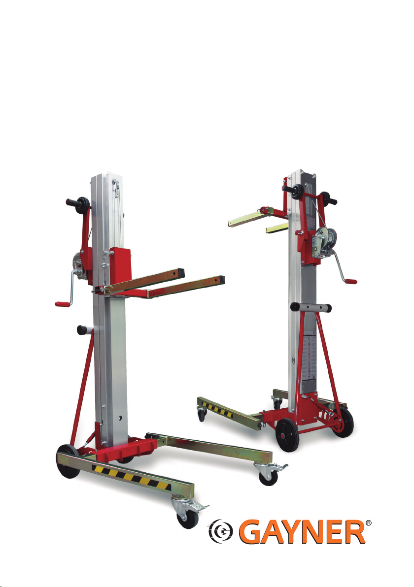
GAYNER ECI User manual
1
INSTRUCCIIONES DE USO / OPERATOR’S MANUAL
ELEVADOR INDUSTRIAL DE CARGA
INDUSTRIAL MATERIAL LIFTS
ECI
ECI-150/2,90 - ECI-200/6,30 - ECI-300/3,85 - ECI-300/6,50 - ECI-400/3,55 - ECI-400/6,50

2

3
CONTENIDO
Introducción 3
Obligaciones del propietario y el usuario 3
Normas de seguridad 4-5
Inspección previa 6
Instrucciones de uso 6-7-8-9
Transporte 10
Mantenimiento 10
Garantía 11
Componentes 12
Certificados 23
Hoja de mantenimiento de la torre 24-25
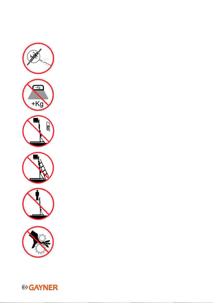
¡PELIGRO!
No cumplir con las normas de seguridad e instrucciones de uso de este manual puede
causar daños en la torre, en la carga y en propiedades. Se debe respetar todas las
normas para evitar daños personales, incluso la muerte.
INTRODUCCIÓN
Gracias por haber elegido una torre de elevación GAYNER. Su Torre ECI ha sido comprobada y chequeada antes de salir de fábrica,
para garantizar que esté en perfectas condiciones. Para mantener el buen estado y garantizar su seguridad durante el uso de la
torre es absolutamente necesario leer, entender y obedecer las instrucciones de seguridad y uso de este manual, porque contiene
información que le dará un conocimiento sobre el funcionamiento del elevador y garantizará una máxima seguridad durante su uso.
Importante: Daños causados por no seguir este manual/normas no están cubiertos por la garantía. Ni el distribuidor, ni el fabri-
cante aceptan ningún tipo de reclamación de daños a propiedades y a personas si no se han seguido estas instrucciones.
OBLIGACIONES DEL PROPIETARIO Y EL USUARIO
Todos los técnicos que lleven a cabo la instalación, uso y mantenimiento de esta torre deben:
- Estar suficientemente cualificados y entrenados.
- Seguir las instrucciones de este manual.
- Conservar este manual en todo momento.
- Facilitar este manual a futuros propietarios y/o usuarios de esta torre. Este manual tiene que ser como un componente
más de la torre y por lo tanto debe estar acompañando a la torre en todo momento.
- Si el manual se extravía contacte con su distribuidor o con el fabricante (GAYNER)
Antes de utilizar la torre por primera vez, verificar que no existen daños causados por el transporte. En el caso de encontrar algún
daño, contactar con su distribuidor y no utilizar el elevador ECI hasta que no esté en perfectas condiciones.

4
NORMAS DE SEGURIDAD
SEGURIDAD DE MONTAJE Y ZONA DE MONTAJE
Antes de realizar cualquier operación, tenga en cuenta las siguientes situaciones de riesgo y evítelas:
· Desniveles o agujeros que impiden que la torre esté nivelada.
· Baches, obstáculos en el suelo o escombros. Lugares peligrosos.
· Superficies inestables o deslizantes. Obstáculos elevados o cables de alta tensión.
· Superficies sin la estabilidad suficiente para resistir las fuerzas de carga de la torre.
· Condiciones meteorológicas y de viento extremas.
· Presencia de personas no autorizadas.
· Cuando la carga esté elevada, no permita que nadie permanezca debajo de la torre ECI.
Asegurarse que una zona de seguridad esta acotada alrededor de la torre, la cual debería tener un
diámetro de 1,5 veces la altura de la torre.
· No bajar la carga mientras haya alguna persona o algún obstáculo debajo.
· Nunca utilizar el elevador ECI con vientos fuertes.
· No utilizar el Elevador en exteriores cuando haya rayos, truenos o clima adverso... En caso de
condiciones extremas no utilizar la Torre ECI.
NOTA: incrementar la superficie de la carga reducirá la estabilidad de la torre en condiciones
ventosas.
· Evite pasar por superficies irregulares o con escombros cuando desplace una grúa elevadora ECI
con las patas plegadas.
· Nunca utilizar sobre superficies móviles o vehículos.
· Colocar el elevador de carga ECI sobre superficies firmes y sólidas.
· Esta torre de elevación ECI no está aislada eléctricamente y no protege en modo alguno si se
aproxima o entra en contacto con alguna fuente de energía eléctrica.
· Si la torre de elevación ECI entra en contacto con líneas eléctricas activas, aléjese de ella.
El personal no debe tocar ni manejar la torre ECI hasta que las líneas eléctricas hayan sido
desconectadas.
· Mantenerse a una distancia prudencial de las líneas y aparatos eléctricos, respetando las
normas gubernamentales pertinentes.
· No utilizar la torre ECI como conexión a tierra (masa) para soldar.
· Antes de instalar el elevador asegurar que la superficie de instalación puede soportar una carga
puntual 5 veces a la de la torre.
· Comprobar el área de trabajo por si hubieran obstáculos salientes por encima de la torre
(letreros, cables, balcones..).
5
NORMAS DE SEGURIDAD
NORMAS DE SEGURIDAD PARA EL USO DE LA TORRE
· Antes de utilizar la torre ECI, efectúe siempre una inspección previa minuciosa siguiendo
las instrucciones de inspección pre-uso. No utilice ningún elevador que esté dañado o que no
funcione correctamente.
·
No utilice ninguna torre
ECI
que tenga cables gastados, deshilachados, con dobleces o dañados.
· No sustituya ninguna de las piezas vitales para la estabilidad o la estructura de la torre ECI.
Si fuera necesario cambiar un componente, tiene que ser sustituido por un recambio original.
· No sobrepasar los parámetros de carga indicados por el fabricante GAYNER.
· No elevar la carga a menos que las patas de la grúa ECI estén correctamente colocadas y sus
seguros de bloqueo fijados y los frenos de las ruedas activados. No ajuste ni quite las patas
cuando este elevada la carga.
· No elevar la torre ECI a menos que la carga esté correctamente colocada, centrada y bien sujeta
a las horquillas. El peso de la carga sólo puede actuar en sentido vertical.
· Nunca instalar objetos que tengan un superficie grande que pueda crear un efecto vela en
condiciones ventosas. Si fuera totalmente necesario contacte con su distribuidor o el fabricante
(GAYNER) para consejos de seguridad.
· Si se deja desatendida la torre ECI con carga, asegúrese de impedir el uso a personal no autori-
zado. El personal no autorizado podría intentar manejar la torre ECI sin una formación adecuada,
originando situaciones peligrosas.
· Asegure la carga con un sistema de seguridad secundario así como con eslingas, cables o
cadenas, las cuales deben ser sobredimensionadas para garantizar total seguridad.
· No someta la torre ECI a fuerzas horizontales ni a cargas laterales subiendo o bajando cargas
fijas o que sobresalgan por los lados, ni apoyar escaleras ni andamios contra la torre.
· No utilice la torre ECI para elevar personas. No subir por el mástil, sentarse o colocarse en las
horquillas.
· No manipular el cabrestante. No engrase ni lubrique el mecanismo de freno.
· Mantenerse alejado de las zonas de peligro. No coger el cable con las manos.
· El instalador tiene la obligación de asegurarse que se cumple en todo momento los reque-
rimientos de seguridad especificado por el fabricante y del lugar de instalación, así como la
capacidad y experiencia de sus compañeros/trabajadores.
· No quitar los adhesivos de seguridad del fabricante; si se quitan se cancela la garantía de dicho
producto.
NOTA: Cuando este elevador se utiliza en un sitio público se deben cumplir una serie de instrucciones de seguridad que este
manual solo puede facilitar en parte. En consecuencia el usuario tiene la obligación de informarse él mismo de las normativas de
seguridad gubernamentales vigentes y tomarlas en cuenta en la planificación de una instalación.
6
INSPECCIÓN PREVIA AL MANEJO DE LA MÁQUINA
¡PRECAUCIÓN! Se debe realizar una inspección previa de la torre antes de cada uso. Compruebe los daños visibles del
elevador, así como si falta algún componente o si se ha realizado modificaciones no autorizadas.
No utilice la torre si esta inspección revelara alguna condición adversa que podría afectar la seguridad de la torre.
¡ADVERTENCIA!
Si durante la inspección previa o en la comprobación de funciones se detectan daños o no
hay un funcionamiento adecuado, la torre deber ser retirada de servicio y reparada por un técnico autorizado.
Chequear los siguientes componentes y partes de la torre:
- Los componentes del cabrestante
- Componentes de la base
- Patas estabilizadoras y ruedas
- Perfiles de aluminio y rodamientos
- Cable (dobleces, desgastes o deformaciones)
- Asegurar que los adhesivos están presentes y legibles
Chequear toda la máquina para detectar posibles:
- Abolladuras y daños
- Corrosión u óxido
- Grietas en la soldadura
INSTRUCIONES DE USO
¡PELIGRO!
Utilizar la lógica y el sentido común para su utilización. Esta torre es un producto complejo y diseñado
para su uso profesional. Asegurar que todo el personal esté correctamente
entrenado y enseñado del contenido de este manual y los peligros
relacionados con el uso del elevador.
INSTALACIÓN
¡PRECAUCIÓN!
Comprobar el área de trabajo por si hubiera obstáculos salientes por encima de la torre
(letreros, cables, balcones, etc.). SIEMPRE seguir las instrucciones de seguridad de
montaje, zona de montaje y uso de la torre de este manual.
7
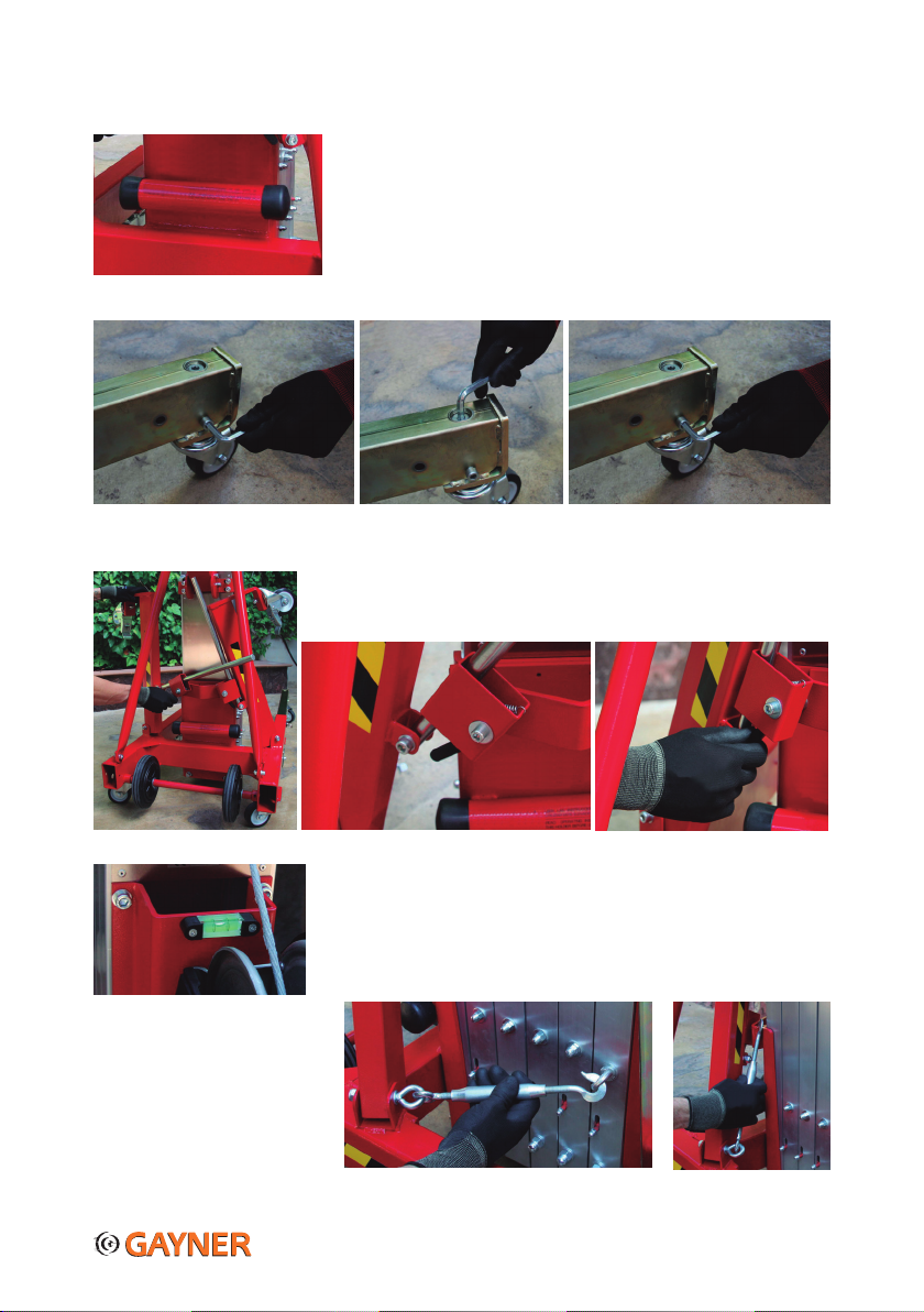
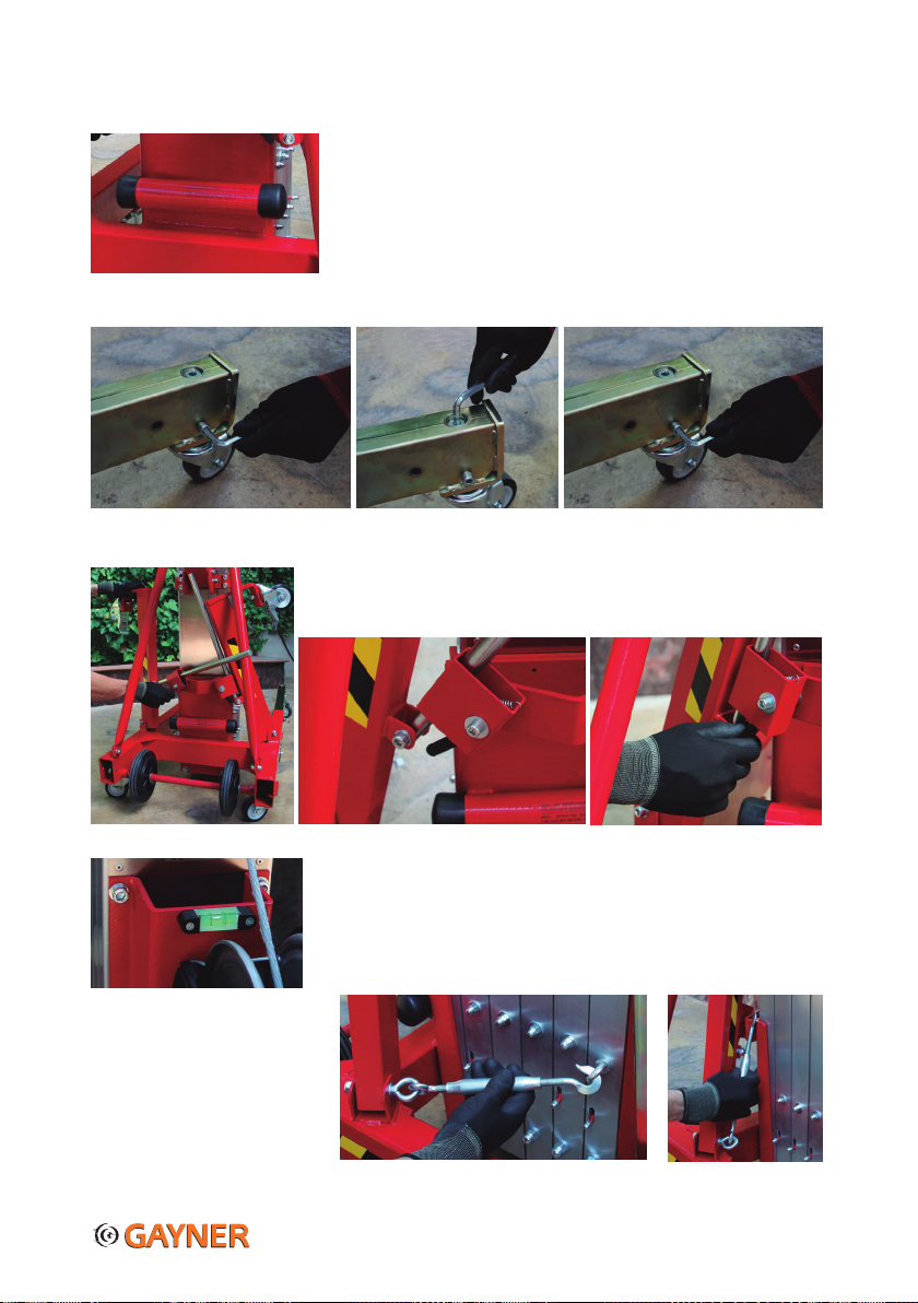
Coloque la torre ECI en el lugar de trabajo deseado.
1.- Extraer las patas estabilizadoras delanteras de la base, colocarlas en los receptá-
culos frontales y fijarlas con los pasadores imantados.* Ajustar/nivelar cada una de
las dos ruedas hasta que estén tocando el suelo. Esta acción se realizará con la llave
Allen que se suministra (dentro del portadocumentos) de la siguiente forma:
a) Desbloquear el husillo ubicado en la parte lateral de la pata.
b) Ajustar el husillo hasta que la rueda toque el suelo.
c) Volver a bloquear el husillo.
* Las patas también se puede colocar en la parte trasera de la base para trabajar a ras de pared (se necesita contrapeso).
2.- Desplegar las patas estabilizadoras laterales, empezando con la pata cuya varilla
esté más cerca del usuario (ver fotos).
3.-Comprobar que la torre ECI esté nivelada, tomando como referencia el indicador
de nivel de burbuja. MUY IMPORTANTE: Las 8 ruedas tienen que estar SIEMPRE en
contacto con el suelo.
4.-Quitar el gancho de bloqueo de los perfiles girando la parte central para alargarlo y
engancharlo de nuevo en la torre, ver las siguientes fotos.
5.- Coloque las horquillas en posición horizontal y fíjelas con los pasadores
imantados.
A B
Portadocumentos
C

8
¿CÓMO INVERTIR LAS HORQUILLAS?
Aflojar la tuerca y quitar el tornillo que sujeta el conjunto al perfil del carro. Invertir las horquillas y volver a colocar el tornillo.
COMPROBACION DE LAS FUNCIONES
1.- Colocar una carga de prueba en las horquillas y fijarla.
2.- Subir y bajar el elevador siguiendo las instrucciones de uso que se indican a continuación para asegurar que el elevador
funciona correctamente y que el cabrestante trabaja con suavidad, sin tirones ni agarrotamientos.
¿CÓMO TRASLADAR LA TORRE AL ÁREA DE TRABAJO?
Sin carga:
- En posición vertical, utilizar las cuatro ruedas de la base ayudándose del mango.
- En posición horizontal, utilizar las ruedas de transporte superiores e inferiores (asegurar que el gancho de bloqueo está puesto).
Con carga: Aunque lo más conveniente es trasladar la torre al lugar de trabajo sin carga, también puede hacerse con carga,
siempre y cuando la torre se deslice sobre sus 8 ruedas direccionales y se encuentre en una superficie nivelada. Mantener la carga
en la posición más baja posible en todo momento.
ELEVACIÓN DE LA CARGA
Colocar la carga en las horquillas, lo más cerca posible de la torre y verificar que el peso de la carga sólo actúa en sentido verti-
cal. Asegúrela mediante cables, eslingas, cadenas, etc. NOTA: La carga máxima del elevador disminuye en función a la distancia
de la carga con el cuerpo de la torre; consulte la tabla de capacidad de carga.
¡ADVERTENCIA!
* Si la carga no se coloca correctamente, puede causar graves daños, incluso la muerte.
* Verificar que la carga a elevar no excede de la carga máxima recomendada.
1.– Para elevar la carga, empiece a dar vueltas a la manivela del cabrestante en el sentido de las agujas del reloj y se elevarán los
perfiles (puede ser en cualquier orden).
2.- Cuando llegue a la altura deseada, deje de dar vueltas a la manivela del cabrestante.
IMPORTANTE: Dejar de accionar las manivelas del cabrestante cuando se note que hay una mayor resistencia. Esto está indicando
que la torre ha llegado a su altura máxima.
MUY PELIGROSO: Forzar el cabrestante podría causar daños internos en el elevador.
DESCENSO DE LA CARGA
1.– Para descender la carga, empiece a dar vueltas a la manivela del cabrestante en el sentido contrario a las agujas del reloj y
comenzaran a bajar los perfiles.
2.- Cuando bajen totalmente los perfiles, deje de dar vueltas a la manivela del cabrestante.
BLOQUEO DE LA CARGA/SISTEMAS DE SEGURIDAD
CABRESTANTE AUTOFRENABLE
Si se deja de accionar la manivela del cabrestante, el freno de éste actúa y la carga se queda bloqueada.
SISTEMA IPB (Sistema de Freno Pendular Interno)
Cada perfil/mástil incorpora un freno de seguridad activado por gravedad, que mantiene la carga en
su sitio en caso de que el cable llegara a aflojarse/romperse.
Cuando la cuña de freno está actuando, podrá verse en el perfil del mástil. Una vez liberada la cuña
de freno, ésta girará hasta llegar a su posición normal (y dejará de ser visible).

9
¿CÓMO DESBLOQUEAR LOS TRAMOS SI EL FRENO (Sistema IPB) HA ACTUADO?
Si se ha activado el freno debido a un doblez en el cable, elevar el tramo de la torre, accionando la manivela del cabrestante, de
esta manera el cable se volverá a tensar y el freno se desactivará automáticamente y se puede seguir trabajando con normalidad.
Si se ha activado el freno debido a la rotura del cable, se deberá desbloquear de la siguiente forma:
1.- Se recomienda si es posible quitar la carga de la torre.
2.- Con una carretilla elevadora u otra torre ECI, elevar el perfil (más cerca de la base)
por la parte de abajo suficientemente para desbloquear el freno y proceder a bajar el perfil.
Si haciendo esta acción el freno se queda enganchado, se tiene que desbloquear mediante
los gatillos (MSU); levantar cada perfil y accionar los gatillos.
3.- Continuar bajando la torre, tramo por tramo de la misma forma.
DESPUÉS DE CADA USO
1.- Bajar las horquillas completamente y desmontar cualquier adaptador que se haya
fijado en las mismas.
2.- Asegurar que las horquillas estén en la posición de almacenaje (posición vertical).
3.- Plegar las patas abatibles presionando el gatillo situado en la parte trasera de la
torre (ver foto en las instrucciones de instalación).
NOTA: Si las patas parecen estar bloqueadas, nivelar la torre mediante los husillos
colocadas en las patas frontales hasta poder plegarlas.
4.- Desmontar las patas/estabilizadoras y colocarlas en la parte trasera de la base
con las ruedas hacia arriba como figura en la imagen.
IMPORTANTE: Colocar el seguro de los perfiles para evitar su deslizamiento durante
el transporte horizontal.
5.- Elija un lugar de almacenamiento seguro con una superficie firme y llana,
resguardado de la intemperie y sin obstáculos ni tráfico.

10
TRANSPORTE
- El vehículo de transporte debe estar aparcado en una superficie nivelada.
- El vehículo de transporte debe estar bien sujeto para impedir que se desplace mientras se carga la torre ECI.
- Asegurar de que la capacidad del vehículo, las superficies de carga y las cadenas o correas sean capaces de soportar el peso de
la torre ECI.
- La Torre ECI debe estar bien fijada al vehículo de transporte mediante cadenas o correas con suficiente capacidad de carga.
- Colocar la torre ECI junto al vehículo. Utilizar las ruedas de transporte para facilitar su carga y transporte en el vehículo.
- Colocar las patas en los receptáculos traseros para maniobrar la torre en rampas.
MANTENIMIENTO
- La torre ECI sale de fábrica ya engrasada y preparada para su utilización. Se recomienda que se engrase periódicamente los
tramos y poleas de la torre.
MUY IMPORTANTE: No engrasar ni lubricar el mecanismo de freno del cabrestante. Evitar la presencia de aceite o grasa en las
superficies de frenado.
- Con el fin de comprobar el estado de todos sus componentes, se debe realizar una inspección técnica periódica de la torre ECI
por un servicio técnico autorizado por GAYNER. La periodicidad de las revisiones, está sujeta a las normativas de cada país.
- Su torre se compone de piezas de alta calidad y elevada duración. Si fuera necesario cambiar un componente, es importante que
sea sustituido por una pieza de recambio original. GAYNER no se responsabiliza de los daños que pueda ocasionar a la torre el
empleo de recambios o componentes no originales. La garantía no será válida si se incorporan piezas que no sean originales o si se
realiza alguna modificación en la torre.
- No sustituya ninguna de las piezas vitales para la estabilidad o la estructura de la torre ECI. Si fuera necesario cambiar un
componente, por favor contacte con tu distribuidor o el fabricante GAYNER.

11
GARANTÍA
· Las torres de elevación ECI están garantizadas contra todo defecto de
fabricación por un periodo de 24 meses fecha factura. Dicha garantía cubre
la reposición de las partes defectuosas y la mano de obra. Los portes serán
siempre a cargo del comprador. Los envíos para reparación en garantía de-
ben ser efectuados a portes pagados y deberán incluir una nota detallada
con las anomalías o averías observadas.
· GAYNER no se hará responsable de los daños de cualquier naturaleza que
pudieran derivarse de una utilización inadecuada o del desgaste normal del
producto. Así como aquellos productos que hayan sufrido modificaciones
por parte del cliente sin el consentimiento expreso de GAYNER.
· GAYNER no se hará responsable de daños personales o materiales
resultantes de negligencia o una inadecuada utilización, adaptación o
mantenimiento de la torre.
· Si los adhesivos de seguridad de la torre han sido eliminados se cance-
lará la garantía.
· En el caso de componentes fabricados por terceras
Palau de Plegamans, 15 - 08213 POLINYA (Barcelona)
Tlf: (+34) 93 713 59 59
Fax: (+34) 93 713 13 17
info@gayner.net
www.gayner.es
Certificado de Conformidad
La empresa:
GAYNER S.A.
c/ Palau de Plegamans, 15
08213 - Polinyà (Barcelona)
Tel. 93 713 59 59
Fax. 937131317
http://www.gayner.net -E-mail: info@gayner.net
Declara bajo su única responsabilidad que las siguientes máquinas:
Código
74-452/10
74-452/20
74-452/30
74-452/35
74-452/40
74-452/45
Referencia
ECI-150/2,90
ECI-200/6,30
ECI-300/3,85
ECI-300/6,50
ECI-400/3,55
ECI-400/6,50
CargaMáx.
150 Kg.
200 Kg.
300 Kg.
300 Kg.
400 Kg.
400 Kg.
AlturaMáx.
Trabajo
2,90 m.
6,30 m.
3,85 m.
6,50 m.
3,55 m.
6,50 m.
AlturaMin.
Trabajo
2,70 m.
6,10 m.
3,45 m.
6,10 m.
3,15 m.
6,10 m.
Son conformes con las exigencias del Sistema de Calidad según las siguientes Normativas y
Reglamentos:
• 2006/42/CE
• DIN 56921
• DIN 4113-2
Y tiene una garantía que comprende la reparación o reemplazo gratuito de las piezas defectuosas.
Los Elevadores de Carga Industrial modelos ECI-150/2.90, ECI-200/6.30, ECI-300/3.85, ECI-
300/6.50, ECI-400/3.55, ECI-400/6.50 están sometidos a los controles de seguridad y pruebas de
resistencia realizadas en la fábrica de producción.
Polinyà (Barcelona) España Departamento de calidad.
Junio 2017
SOLUCIONES EN MOVIMIENTO
12
1.-
2.-
3.-
4.-
5.-
6.-
7.-
8.-
9.-
10.-
11.-
12.-
13.-
14.-
15.-
16.-
17.-
18.-
19.-
20.-
21.-
22.-
23.-
24.-
25.-
26.-
27.-
28.-
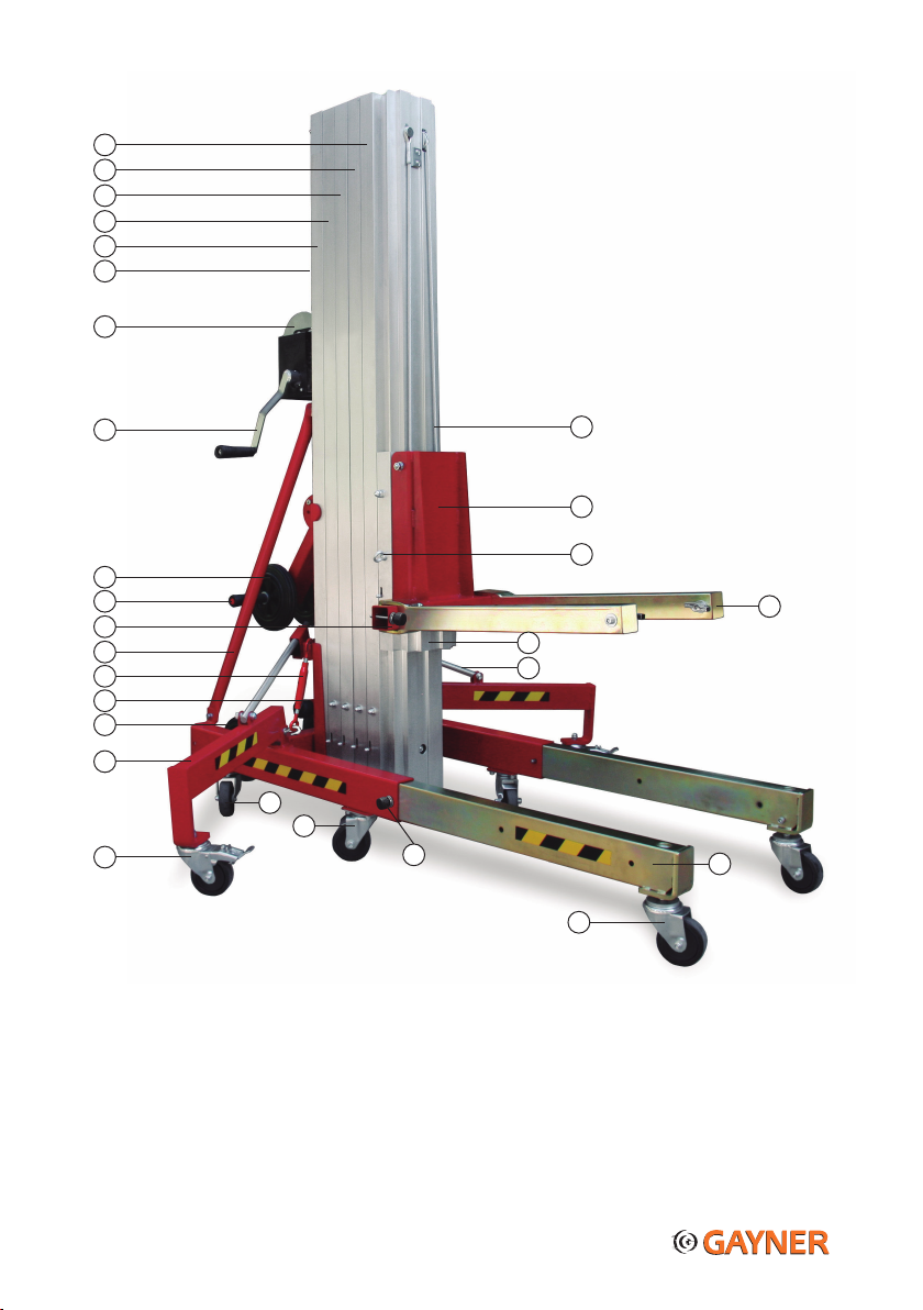
1er Perfil / Mástil*
2oPerfil / Mástil*
3er Perfil / Mástil*
4oPerfil / Mástil*
5oPerfil / Mástil*
Nivel de Burbuja
Cabestrante
Manivela de Cabestrante
Ruedas de Transporte superiores
Mango Direccional
Pasador de Seguridad Imantado
Brazos de Refuerzo
Enganche Bloqueo Perfiles
Portadocumentos
Ruedas de Transporte Inferiores
Patas Estabilizadoras Laterales
Ruedas Laterales con Freno
Ruedas Base
Ruedas Base con Freno
Pasador de Seguridad Imantado
* El número de Perfiles / Mástiles depende del modelo de la torre
Ruedas Niveladoras Patas Frontales
Patas Estabilizadoras Frontales
Barra Estabilizadora
Perfil del Carro
Horquillas
Argolla Bloqueo Perfiles
Conjunto del Carro
Cable ø6
16
15
14
13
12
11
10
9
8
7
6
5
4
3
2
1
17
21
20
19
18
22
23
25
26
27
28
24
COMPONENTES

13
CONTENTS
Introduction 13
Owner and User’s Obligations 13
Operator Safety Instructions 14-55
Pre-operation Inspection 16
Operating Instructions 16-17-18-19
Transport 20
Maintenance 20
Guarantee 21
Components 22
Certificates 23
Maintenance sheet for the tower 24-25
DANGER TO LIFE!
Failure to comply with the safety or operating instructions in the manual may result in
damage to property, serious personal injury or even death!
INTRODUCTION
Thank you for having chosen a GAYNER lifting tower. Your machine left our premises in absolutely perfect condition. To maintain
this condition and to ensure a safe use, it is absolutely necessary for the user to read, understand and obey the safety and
operating instructions in this manual as it contains information that will give you a thorough knowledge of the workings of your
ECI tower and guarantee maximum safety whilst operating it.
Important: Damages caused by the disregard of this user manual are not subject to warranty; neither the dealer nor the manufac-
turer accepts liability for any resulting damages to property or personal injury.
OWNER AND USER’S OBLIGATIONS
Everyone involved with the installation, operation and maintenance of this lifting tower must:
- be sufficiently qualified, trained or experienced
- follow the instructions of this manual
- keep this manual for the entire service life of the product
- pass this manual on to every future owner or user of the tower. This manual should be regarded as a permanent part of
your lift and should remain with the lifting tower at all times.
- If the manual is misplaced please contact your dealer or manufacturer (GAYNER).
Before putting the tower into service please make sure that there is no damage caused during transportation. Should there be any,
consult your dealer or the manufacturer (GAYNER) and do not use the stand.
14
OPERATOR SAFETY INSTRUCTIONS
SET-UP AND WORKING AREA SAFETY
Prior to set-up, be aware of and avoid the following hazardous situations:
· Drop-offs or holes which impede the tower being levelled using only the leveling jacks. Pot holes, obstacles on the
floor or debris.
· Slopes that exceed the adjustment capabilities of the tower.
· Unstable or slippery surfaces.
· Hazardous locations. Aerial obstacles or overhead electric cables.
· Inadequate surface support to withstand all load forces imposed by the tower.
· Weather conditions and strong winds.
· The presence of unauthorised personnel.
· Do not stand under or allow personnel under the ECI tower when the load is raised, making sure
a safety area is blocked around the tower, which should have a diameter of 1.5 times the height
of the tower..
· Do not lower the load unless the area below is clear of personnel and obstructions.
· Never use the ECI lifting tower in strong or gusty wind.
· Do not use this lifting tower outdoors if it is thundering and lightning or adverse weather…Never
use the ECI tower in the event of extreme weather conditions.
NOTE: Increasing the load surface area will decrease machine stability in windy conditions.
· Avoid transporting the ECI lift over uneven surfaces or ground with debris when in the folded
position.
· Never use the tower on moving surfaces or vehicles.
· The ECI lift must always be set up on firm and even surfaces.
· This ECI lifting tower is not electrically insulated and does not protect you if it gets close to or
comes into contact with electricity.
· If the ECI tower comes into contact with electric cable, keep well away. The tower should not be
touched or used until the electricity has been switch off.
· Maintain safe distances away from electrical power lines and apparatus, allowing for mast
movement and electrical line sway or sag, in accordance with applicable local governmental
regulations.
· Do not use the lifting tower as a ground for welding.
· Before installing the tower, make sure the installation area can hold a minimum point load of 5
times the load to be raised.
NOTE: When using this lifting tower in public places or industrial areas, a series of safety
instructions have to be followed that this manual can only give in part. The user must therefore
inform himself/herself on the current governmental safety instructions and take them into
consideration when planning the installation
15
OPERATOR SAFETY INSTRUCTIONS
TOWER USE SAFETY INSTRUCTIONS
· Always carry out a thorough inspection of your ECI tower before each use by following the
pre-operation inspection instructions. Do not use a tower that is damaged or doesn’t work
properly.
·
Never use the
ECI
lifting tower with a worn, frayed, kinked or damaged winch cable.
· Do not exceed the rated load capacity recommended by the manufacturer GAYNER.
· Do not use the ECI lifting tower unless all four outriggers have been properly installed with the
safety bolts fixing them in place and the brakes put on the wheels. Do not adjust or remove the
outriggers while the load is raised.
· Do not raise the ECI tower unless the load is correctly positioned, centred and secured on the
forks. The centre of gravity should always be along a vertical line.
· Never install objects that make a large surface for the wind. If it is absolutely necessary please
contact your dealer or the manufacturer (GAYNER) for safety advice.
· If you are going to leave the ECI tower unattended with a raised load make sure it can’t be used
by unauthorised personnel. Unauthorised personnel could try to use the tower without adequate
training, causing dangerous situations.
· All loads must be secured using a secondary safety system such as slings, cables or chains
which must be oversized i.e. have adequate safety margins, to ensure maximum safety.
· Do not subject the ECI tower to a horizontal force or side load by raising or lowering a fixed or
overhanging load or resting a ladder or scaffold against any part of the machine.
· Do not use the ECI tower as a personnel lifting platform. Do not climb on the mast sections or
sit/stand on the forks.
· Do not tamper with, remove or replace any component of the brake winch. Do not grease the
braking mechanism.
· Keep hands away from all moving parts and pinch points when operating the tower. Do not grasp
the winch cable.
· The installer is responsible for adhering to the load capacity specified by the manufacturer, the
safety requirements in the place of installation and the abilities and experience of co-workers.
· Do not remove the manufacturer’s labels; if removed the guarantee will be null and void.
NOTE: When using this lifting tower in public places or industrial areas, a series of safety instructions have to be followed that
this manual can only give in part. The user must therefore inform himself/herself on the current governmental safety instructions
and take them into consideration when planning the installation..

16
PRE-OPERATION INSPECTION
CAUTION! A pre-operation inspection must be carried out before every use of the tower. Check the tower for damage, impro-
perly installed or missing parts and unauthorised modifications using the list below. Do not use the tower if this
inspection reveals any adverse conditions that could affect the safety of the tower.
WARNING!
If damages or malfunctions are found in either the pre-operation inspection or the function
test the tower should be removed from service and repaired by an authorised technician.
Check the following components and areas of the tower:
- All winch components
- Base components / Stabiliser legs (outriggers)
- Aluminium mast sections
- Cable (kinks, frays or deformations) and pulleys
- Wheels and castors
- Ensure all labels are in place and legible
Check the whole machine for:
- Dents and damage
- Corrosion or rust
- Cracks in welding
OPERATING INSTRUCTIONS
WARNING!
Always use logic and common sense when using the tower. This is a complex product
designed for professional use and should not be operated by amateurs. Ensure all
personnel are correctly trained and instructed on the content of the manual and the
dangers related with operating the tower.
SET-UP
CAUTION!
Check the work area for overhead obstructions or possible hazards before
use (signs cables, balconies, etc.). ALWAYS follow the set-up and working area and
tower use safety instructions in this manual.
17
Position the ECI tower at the desired work site.
1.- Pull the outriggers out of the back leg sockets and insert them into the front
sockets with the wheels downwards. Block them in the position required, making
sure they are fixed in place with the magnetic locking pins.* Adjust the wheels until
they touch the floor with the Allen key provided (found in the manual holder) in the
following way:
a) Unblock the spindle with the bolt found on the side of the leg.
b) Adjust the spindle until the wheel touches the floor.
c) Block the spindle again.
* The legs can be placed in the back of the tower to use it close to a wall (counterweights must be used).
2.- Unfold the side stabiliser legs, starting with the leg with the sliding bar that is
closest to the user (see pictures below).
3.-Make sure the ECI is properly levelled using the spirit level as a reference. VERY
IMPORTANT: The 8 wheels must always be in contact with the ground.
4.-Remove the blocking hook from the aluminium profiles by turning the tube to make
the hook longer and then hook it back onto the tower, as per the following pictures.
5.-Put the forks into the horizontal working position and lock them with the magnetic
locking pins.
A B
Manual holder
C
18
HOW TO PUT THE FORKS IN THE ‘FORKS UP’ POSITION
Remove the nut and bolt that holds the fork carriage to the fork-carriage mast profile. Turn the fork plate 180º, insert it onto the
fork-carriage mast profile and secure the bolt and nut again.
FUNCTION TEST
1.- Place a test load on the forks and secure.
2.- Raise and lower the tower following the below operating instructions to ensure it is functioning correctly and the winch is
operating smoothly and free of hesitation or binding.
HOW TO MOVE THE TOWER TO THE WORK AREA
Without the load:
- In vertical position, use the four wheels on the base with the help of the manoeuvring handle.
- In horizontal position, use the upper and lower transportation wheels, ensuring that the blocking hook is locking the profiles.
With the load: Although the best option is to manoeuvre the tower without the load, but it can also be done with the load, as long
as the 8 wheels on the base and the legs are all touching the ground and the ground is flat. Keep the load at the lowest height at
all times possible.
RAISING THE LOAD
Place the working load on the forks as close to the tower as possible, making sure that the load is totally centred on the forks.
Secure the load using slings, cables, chains, etc. Note: The further away the load is from the tower body the lower the maximum
load weight is; consult load capacity chart.
WARNING!
* If the load isn’t correctly placed on the forks this could cause a serious accident, or even death.
* Ensure that the load you wish to raise does not exceed the rated load capacity recommended by the manufacturer.
1.– To start to raise the load, turn the winch handle in clockwise direction and the profiles will be lifted.
2.- When you reach the desired height stop turning the winch handles and the winch will hold the profiles in place.
IMPORTANT: Stop turning the winch handles when you notice that the movement becomes difficult. This indicates that the tower
has reached its maximum height.
VERY DANGEROUS: Forcing the winch at this point could cause serious internal damage to the tower.
LOWERING THE LOAD
1.– To start to lower the load, turn the winch handle in anti-clockwise direction and the profiles will be lowered.
2.- When you have completely lowered the profiles stop turning the winch handles.
BLOCKING THE LOAD/SAFETY SYSTEMS
AUTO-BRAKE HAND WINCH
If you let go of the winch handle the brake will automatically take affect and block the load in place.
IPB SYSTEM (Internal Pendulum Brake)
Each mast profile has an incorporated safety brake that works by inertia, holding the load in place if
the cable were to become loose or break.
When the jagged component has been activated it can be seen between the mast profiles. Once the
safety brake has been deactivated, it will have gone back to its original position and will no longer be
visible

19
HOW TO UNNBLOCK THE MAST PROFILES IF THE SAFETY BRAKE (IPB System) HAS BEEN ACTIVATED.
If it is activated due to a kink in the cable or sagging, raise the tower by turning the winch handle clockwise, this way the cable
will become tensed again and the safety brake will deactivate automatically, so you can continue too use the tower.
Our towers are fitted with a special deactivation system for when the IPB system is activated due to cable breakage, this system is
called the MSU System. Unblock the tower using the following instructions:
1.- Firstly the load, where possible, must be removed from the tower.
2.- The profile closest to the base must lifted using a forklift truck or another ECI tower,
pushing it up from underneath to unblock the safety brake and then completely lower the
profile. If the safety brake stays blocked when this has been done, it must be unblocked
using the MSU lever system; lift up each profile and then use the lever to unblock them.
3.- Continue to lower the tower, profile by profile in the same way.
AFTER EACH USE
1.- Completely lower the fork carriage and remove any adaptors.
2.- Ensure the forks are in the storage position (vertical position).
3.- Fold the side stabiliser legs. To fold the side stabiliser legs into the vertical, folded
position, press the levers at the back of the tower, see the picture.
NOTE: If the legs won’t fold, adjust the front legs with the adjustable wheels until
they can be folded.
4.- Remove the front legs and store them in the back sockets in the wheels up position
as per the picture.
IMPORTANT: Replace the profile safety hook to stop the profiles from moving during
horizontal transportation.
5.- Select a safe storage location making sure it is: on a firm and level surface,
protected from the elements, clear of obstructions and passage.

20
TRANSPORT
- The transport vehicle must be parked on a level surface. It must be stationary to prevent it from moving whilst loading the ECI
tower.
- Make sure the vehicle capacity, the loading space and chains or straps used are sufficient to withstand the weight of the tower.
- AThe tower must be secured to the vehicle with straps or slings of adequate load capacity.
- La Torre ECI debe estar bien fijada al vehículo de transporte mediante cadenas o correas con suficiente capacidad de carga.
- Place the ECI tower against the vehicle. Use the transportation wheels to help load the tower onto the vehicle.
- The front legs can be inserted in the back of the tower base to manoeuvre it up ramps.
MAINTENANCE
- The ECI lifting tower is released from the warehouse already greased and ready to use. It is recommended that you periodically
(depending on the frequency it is used) grease the mast profiles and internal pulleys.
VERY IMPORTANT: Do not grease the brake mechanism. Do not allow oil or grease on the braking surfaces..
- A regular technical inspection of the ECI tower must be carried out (depending on the regulations in your country and the
frequency of use of the tower) by a GAYNER authorised technician, to establish the condition of all its parts..
- Your GAYNER tower is made with high quality long-lasting components. In the event of having to change a component it is
important that it is replaced with an original spare part. GAYNER will not take responsibility for any direct or indirect consequence
due to the incorrect use, carelessness or bad maintenance. The guarantee will be invalid if nonoriginal components are used or if
any modifications are made to the tower.
- Do not replace parts of the tower that are critical to stability or structure with items of different strength or specification. If it
were necessary to replace parts, please contact your dealer or the manufacturer GAYNER.
This manual suits for next models
6
Table of contents
Languages:
Popular Lifting System manuals by other brands

Power Towers
Power Towers Pecolift Tower manual

Rubi
Rubi Slab Trans Heavy Duty instructions

WERTHER INTERNATIONAL
WERTHER INTERNATIONAL 208I/7 Original instructions

Basta Boatlifts
Basta Boatlifts Over-Center 4.5k37 manual

Upright
Upright MX15 Operator's manual

Joab
Joab EcoDrive VL10U Operation and maintenance manual

Thiele
Thiele TWN 0861 Mounting instructions

Harkness Screens
Harkness Screens SI-100 installation manual

Kelley
Kelley HK-S user manual

Challenger Lifts
Challenger Lifts CL10 Installation, operation & maintenance manual

Magliner
Magliner CooLift CPA48 owner's manual

stellar labs
stellar labs 96-10-24 owner's manual


