4
!
!WARNING
•Study, understand, and follow all printed
materials provided with/on this product before use
.
•Do not exceed rated capacity.
•Use only on hard, level surface.
•This is a lifting device only! Immediately
after lifting, support the forklift with a pair of
appropriately rated forklift stands.
• Position jack perpendicular to the forklift such that
the load is balanced by the remaining two wheels
in contact with surface.
• Only attachments and/ or adapters supplied by
the manufacturer shall be used.
•
Do not move or dolly the vehicle while on the jack.
• No alterations shall be made to this product.
FAILURE TO HEED THESE MARKINGS MAY
RESULT IN PERSONAL INJURY AND/OR
PROPERTY DAMAGE
To avoid crushing and related injuries:
•Never work on, under or around a load
supported only by hydraulic forklift jack.
•Always use adequately rated forklift stands.
• Keep hands, feet and all other body parts out of
the area of the scissors mechanism at all times.
•Do not use this device to lift, level, lower,
support nor move a house, mobile home, travel
trailer, camper or any building structure.
•Be alert and sober when using this product.
Do not operate under the inuence of drugs or
alcohol.
!WARNING
OPERATION
Lifting
WARNING: Ensure hydraulic unit does not
contact vehicle during lift event.
1. Follow the vehicle manufacturer’s recommended
guidelines for lifting. Engage the emergency brake
and chock each unlifted wheel in both directions to
prevent inadvertent vehicle movement.
2.
Close the release valve by turning it clockwise until rm
resistance is felt.
3. Verify lift point, center jack saddle under lift point.
4. Squeeze the lift control valve
(model 28047 only)
or
insert handle into handle sleeve and pump to contact
lift point. To lift, continue pumping until load reaches
desired height.
NOTE: for model 28047, DO NOT operate by air and
by hand pumping at the same time.
5. Transfer the load immediately to appropriately rated
forklift stands.
WARNING:
NEVER use hydraulic jack as a
stand alone
device! ALWAYS transfer the lifted
forklift
IMMEDIATELY to a pair of appropriately
rated forklift stands. Use one pair of forklift stands
per forklift. Rated capacity is per pair only! Do
not exceed rated capacity.
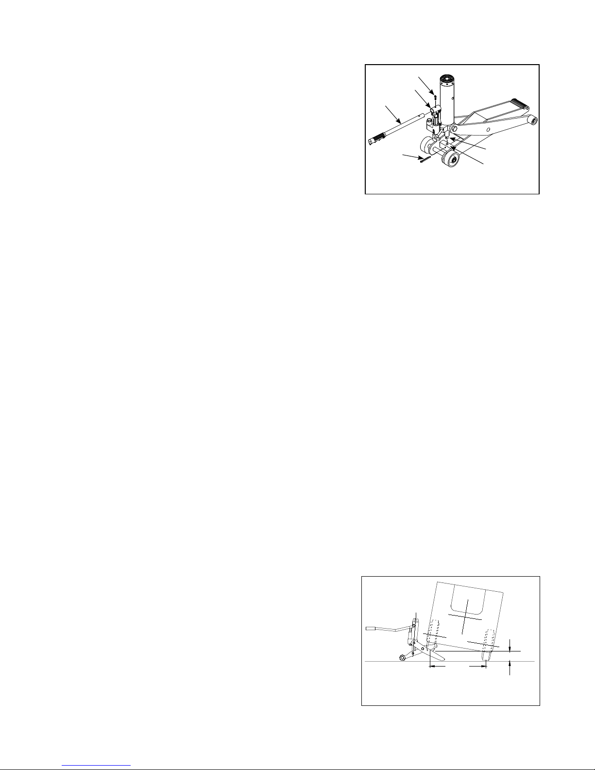
!
X
!WARNING
Never lift from either end of forklift
!WARNING
Lift only on areas of the forklift as
specied by the forklift manufacturer.
Lowering
WARNING:
Be sure all tools and personnel are
clear before
Lowering load. Slowly open the
release valve! The more you turn the knob
counter-clockwise, the faster the load will come
down. Maintain control of the rate of speed at
which the load lowers at all times!
1. Raise forklift high enough to clear the forklift stands.
2.
Remove stands carefully (always used in pairs).
3. Slowly turn the release valve counter-clockwise, but
no more than 1/2 full turn. If the load fails to lower:
a. Use another jack to raise the forklift high enough
to reinstall forklift stands.
b. Remove the malfunctioning jack and then the
forklift stands.
c.
Using the functioning jack to lower the
forklift.
4. After removing jack from under the forklift, fully lower
the saddle and push handle sleeve down to reduce
ram and piston exposure, rust and contamination.
!