Power Towers Nano Owner's manual

Power Towers Ltd,
West House, West Avenue, Wigston, Leicester LE18 2FB, United Kingdom, Tel: +44 (0)116 200 1757, Fax: +44 (0)116 284 9243
Working Dimensions
Maximum working height: 4.50 m
Maximum platform height: 2.50 m
Platform dimensions: 1.00 m x 0.73 m
Working footprint: 1.19 m x 0.75 m
Safe working load: 200 kg (1 person plus tools)
Maximum manual force: 200 N
Max. gradient for operation: 0°
Max. wind force: Indoor use 0 mph
Manual push force on level ground: 9 kg
Maximum total weight inc payload: 485 kg
Maximum castor point load: 180 kgs (1.77 kN)
Max. wheel force: 1.75 kN
Closed Dimensions
Length: 1.195 m
Width: 0.750 m
Height: 1.560 m
Weight: 285 kg
Power Source
Standard 12v DC Electric Motor
Or 240V AC Electric Motor 13A Supply
Or 110V AC Electric Motor 16A Supply
Battery Charger Specification
Input Voltage:
If single voltage: 90-135V AC (UK)
180-265V AC (non-UK)
If dual voltage: 90-265V AC
Frequency: 45-65 Hz
Output: 12V DC, 7A
Power sound level: Less than 70dB

2
Content
Page
3 – 4 Battery Maintenance
5 Battery Charging Fault
6 Checking for Oil Leaks
7 How to Change the Oil in the Hydraulic System
8 Adjusting the Wear Screws (Mast Section)
9 Castor and Wheel Maintenance
10 Replacement of Castor Wheel
11 Gate Latch Adjustment
12 – 13 Removing or Replacing the Hydraulic Pipe
14 – 15 Remove or Replace the Emergency Lowering Valve
16 – 18 Removing or Replacing the Lift Cylinder
19 – 20 Removal and Assembly of the Telescopic Mast

3
Battery Maintenance
Please ensure,the unit is isolated and you use the correct PPE as indicated.
Check the electrolyte level in each of the
battery cells. The electrolyte should be
covering the plates by one to two
millimetres
Check the connections and make sure the
battery is clean
Using a hydrometer, check the specific
gravity of each cell in the battery. The
hydrometer should read between 1.28
and 1.285, and all cells should be equal.

4
Use a voltmeter to check the voltage. The
reading should be approximately 13 volts.

5
Battery Charging Fault
Please ensure,the unit is isolated and you use the correct PPE as indicated.
Check the battery charger lights when
first switched on (Display Green LED On,
Amber LED blinking fast is bulk load,
blinking slow is absorption, on float, off
storage.)
If the both charger lights flash slowly,
check the fuse, battery connections and
then the battery condition as outlined in
the chapter: ‘Battery Maintenance.
Fuse can be found underneath the fuse
cover on the charger.
Fuse cover can be identified by the red
arrow.
If there are no lights on the charger,
check the supply connections which can
be found on the right hand side of the
chassis

6
Checking for Oil Leaks
Please ensure,the unit is isolated and you use the correct PPE as indicated.
Remove covers spine end cap and the
chassis top cover and check the pipe end
connections at the base of the lift
cylinder ensure the union is torque to
40Nm and also check the connections on
top of the power pack.
Check the lowering valve spool and the
valve screw cartridge on the side of the
power pack.
7
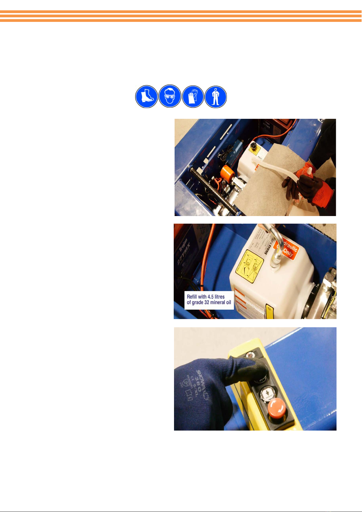
How to Change the Oil in the Hydraulic System
Please ensure,the unit is isolated and you use the correct PPE as indicated.
Use a syringe to empty the hydraulic
reservoir.
Refill with 4.5 litres of grade 32 mineral oil.
Elevate the machine from the Pendant
controls to ensure the platform reaches
full travel. If not add a little more oil.
Do not keep the pump running with no oil
in the tank.
8
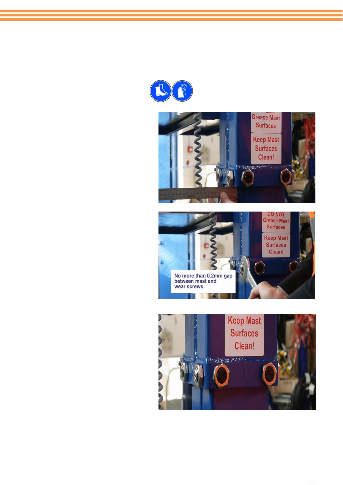
Adjusting the Wear Screws (Mast Section)
Please ensure, the unit is isolated and you use the correct PPE as indicated.
Raise the mast sections using the lift
control to gain comfortable access to
the wear screws. Align the outer
section to the inner section so that the
gap between the inner section and the
outer section is equidistant from side to
side. (18mm)
Screw in the four side wear screws, so
that they just make contact with the
0.2 feeder gauge, slightly back if the
gauge cannot be withdrawn, and
tighten
the
lock nut. Repeat the
process for the middle mast section to
lower the
mast.
Adjust the two rear plastic wear screws
in a similar manner. It is not possible to
adjust the clearance between the inner
and outer sections with the rear screws.
Remove. Operate the lift function to
ensure the outer and middle sections
do not bind. Back off slightly any wear
screws found to be pinching so that
both mast sections travel up and down
freely.

9
Castor and Wheel Maintenance
Please ensure, the unit is isolated and you use the correct PPE as indicated.
Ensure the Castor bolt is torque to
55Nm, If the castor bolts are to be found
to be worn then replace with PT-M-170.
Again ensure this is tightened and
torqued to 55Nm.
Ensure the wheel spins freely and
rotates on the castor if the wheel
doesn’t move freely after being
tightened to the required torque then fit
a spacer washer. Check for any damage,
the breaking latch moves freely and the
castor is not twisted.

10
Replacement of Castor Wheel
Please ensure, the unit is isolated and you use the correct PPE as indicated.
Raise the machine from the ground with
a suitable hoist or block the front of the
machine so the castor wheels are clear of
the ground by approximately 50
millimetres. Undo the fixing bolt and
remove the castor.
Refitting is a reverse of this procedure
but it is essential to fit a spacer washer
but when tightening the fixing bolt,
ensure it is torque to 55Nm, ensure the
wheel moves freely.

11
Gate Latch Adjustment
Please ensure, the unit is isolated and you use the correct PPE as indicated.
Offer the gate to the hinges and pass
the long pivot bolt downward through
the top hinge bracket. When feeding
downward, slide the bolt though the
spring until just before passing through
the lower hinge bracket. Twist the
lower arm of the spring behind the
gate upright and then pass the pivot
bolt through the lower hinge.
Allow the gate to close, and check that
the “U” pin locates correctly in the jaw
of the of the gate latch. If the “U” pin is
too low, raise the pivot bolt slightly
above the lower hinge and fit one or
two M10 washers as required. Pass
the pivot bolt all the way through the
hinge plates, fit and tighten a lock nut
and washer
12
Removing or Replacing the Hydraulic Pipe
Please ensure, the unit is isolated and you use the correct PPE as indicated.
Lower the platform to the transport
position, raise the cage and lock the gas
strut. Open the manual emergency
lowering valve and allow the oil to drain to
the tank for a minute or two.
Direction of twist is indicated by the red
arrow.
Remove the spine end cap and then
disconnect the hydraulic connection to the
cylinder
Move to the top of the power pack and
remove the chassis cover. Identify the
steel pipe connection and undo the
fittings. There may be a very small amount
of oil loss at this time. The pipe now can
be withdrawn.

13
The new pipe is refitted in the reverse
sequence. Ensure to connect both ends
of the pipe loosely to ensure correct
alignment and then tighten the cylinder
connection first, taking care not to twist
the pipe. It may be necessary to slacken
the two power pack mounting screws
located under the middle of the power
pack to enable correct alignment.
When replacing the power pack mounting screws
ensure to apply a small amount of Loctite 648

14
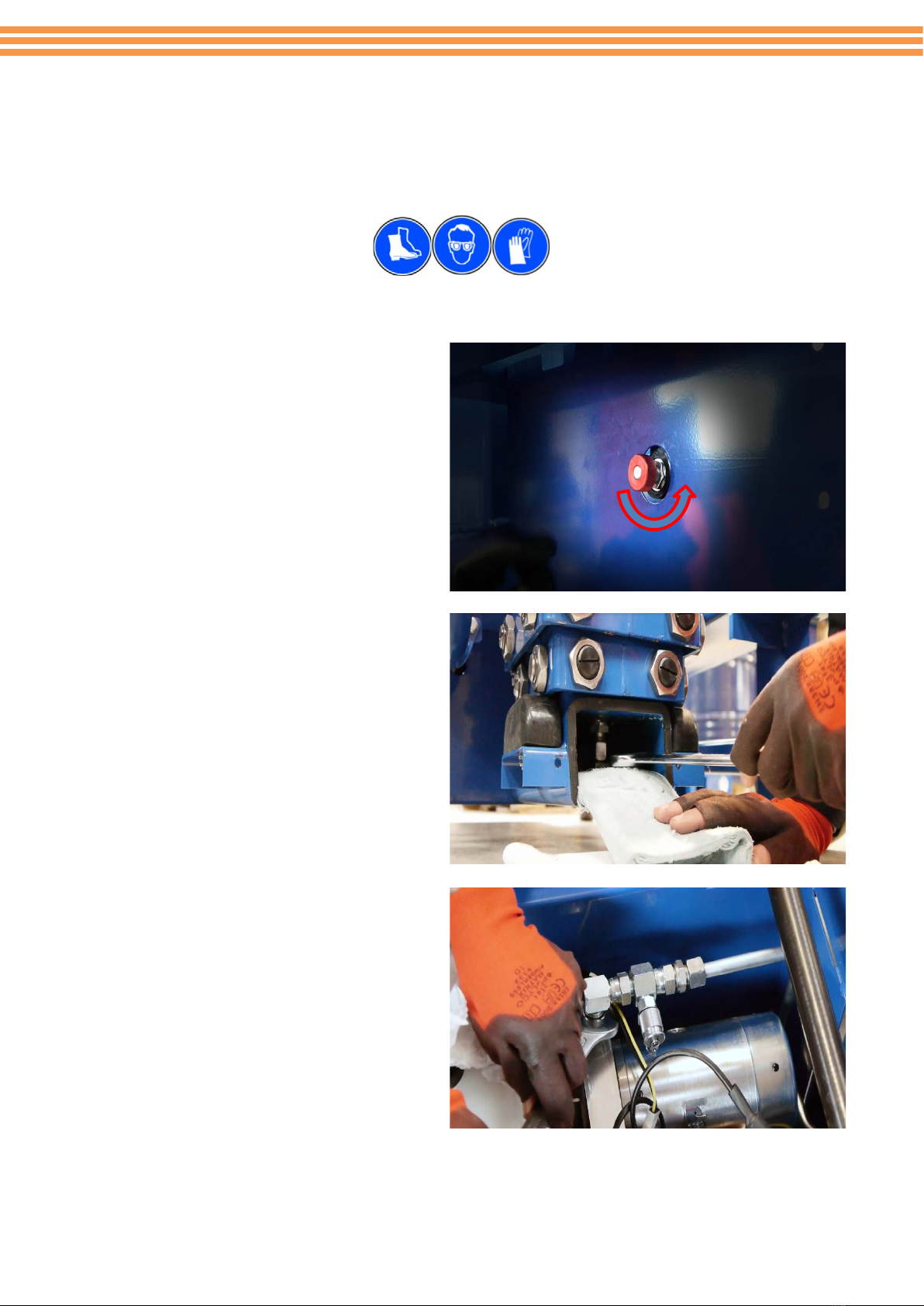
Remove or Replace the Emergency Lowering Valve
Please ensure, the unit is isolated and you use the correct PPE as indicated.
Fully lower the platform and open the
emergency-lowering valve for a minute or
two, to fully drain the oil. To open the
emergency lowering valve push the milled
knobs in and slightly turn anticlockwise.
Direction of twist is indicated by the red
arrow.
Raise the platform and lock the gas strut.
Either lift the machine on a suitable hoist
or raise the base of the machine on the
emergency lowering valve side and chock
up in a safe manner.
Place some oil soak cloths around the
power pack pipe connection and undo the
pipe connection. Locate the spine cap and
remove, loosen the pipe, there may be a
small amount of oil spillage. Locate the
two power pack fixing screws, located
under the base of the machine, below the
centre of the power pack and undo

15
Move the power pack sideways to gain full
access to the lowering valve. Remove the
knurled knob and solenoid, and then the
valve cartridge
Refit the new or repaired valve cartridge
and reassemble using the reverse
sequence. Set the knurled knob in the
normally closed locked position to close
the emergency lowering valve push in and
slightly turn clockwise, check that the
machine elevates, and remains stationary
when elevated, when the machine is back
on the ground in a stable condition.

16
Removing or Replacing the Lift Cylinder
Please ensure, the unit is isolated and you use the correct PPE as indicated.
Open the emergency lowering valve and
ensure the platform is fully lowered.
Allow the oil to drain for a minute or
two. To open the emergency lowering
valve push the milled knobs in and
slightly turn anticlockwise.
Direction of twist is indicated by the red
arrow.
Remove the tool tray on top of the mast.
Remove the countersunk screw in the
centre of the mast cap.

17
Undo the four bolts situated around the
mast cap and remove.
Remove the Spine End Cap.
Place suitable oil soak rags on the floor
around the base of the machine at the
rear, Disconnect the hydraulic pipe from
the cylinder, around 0.25 litres of oil
may be lost. It may be essential to
loosen the pipe on top of the power
pack.

18
With a sling or hoist lift the cylinder
clear of the machine. Reverse the
procedure to refit the cylinder. When
reassembling the mast cap please
ensure to apply a small amount of
Loctite 648 to the locking bolts and
torque to 30 Nm.

19
Removal and Assembly of the Telescopic Mast
Please ensure, the unit is isolated and you use the correct PPE as indicated.
Fully lower the platform and open the
emergency-lowering valve for a minute
or two, to fully drain the oil. To open
the emergency lowering valve push the
milled knobs in and slightly turn
anticlockwise. Display push and turn
anticlockwise.
Tilt the platform upward and support
with a sling or hoist. Remove the gas
strut.
Lower the cage and undo the two main
fixing bolts. With the sling or hoist,
remove the complete cage.

20
Remove the tool tray on top of the
mast. Remove the countersunk screw
in the centre of the mast cap. Undo
the four bolts surrounding the mast cap
and remove.
With the hoist, raise the mast outer
section a short distance to a convenient
position and remove the roller and
wear screws. When removed lift the
mast section clear of the mast using the
hoist taking care to clear the inner stop
blocks as the mast is raised.
Repeat the process for the mast middle
section. Access can now be gained for
any maintenance or remedial work
required. Reverse the procedure to
reassemble the mast and platform.
When reassembling the mast cap
please ensure to apply a small amount
of Loctite 648 to the locking bolts and
torque to 30 Nm
Table of contents
Other Power Towers Lifting System manuals


Popular Lifting System manuals by other brands


DINGLI
DINGLI AMWP8-1200 operators manual with maintenance information

AussieCarHoists
AussieCarHoists YL5000 user manual

Braun
Braun NVL Vista 02 Series Service manual

LSP inc.
LSP inc. LSC1576 owner's manual

STARKE ARVID
STARKE ARVID Vakuflex 280 operating instructions

Sportsman
Sportsman ALBLFT Assembly instructions


