Central Machinery 95647 Quick reference guide

Model 43681
Lathe Stand
Copyright ©2006byHarborFreightTools.AllRights Reserved.
No portion of this manual or any artwork contained herein may be reproduced in any manner, shape or form
withoutthe expresswritten consentofHarbor FreightTools.
For technical questions and replacement parts, please call 1-800-444-3353.
Assembly & Operating Instructions
www.harborfreight.com
Model 95647
(For Use With Item 43681 - Gap Bed Lathe)
(LatheNotIncluded)

SAVETHIS MANUAL
Youwillneedthemanual forthesafetywarningsandcautions,assembly instructions,operatingprocedures,
maintenanceprocedures,troubleshooting,partslist,anddiagram.Keepyourinvoice withthis manual.
Writetheinvoicenumberonthe insideof thefrontcover.Keepboth thismanual andyourinvoiceina safe,
dryplace forfuturereference.
READALLINSTRUCTIONSBEFORE USINGTHIS STAND!
SPECIFICATIONS
NOTICE
TheWarnings, Cautions, andInstructionsdiscussedinthis instruction manualcannotcoverall
possibleconditionsandsituationsthatmayoccur.Itmustbeunderstoodbytheoperatorthat
commonsenseandcaution are factorswhichcannotbebuiltinto this product,butmustbe
suppliedbytheoperator.
Page 2 SKU # 95647
Material Mild Steel
Frame Metal Thickness .11” Thick Carbon Steel
Left Cabinet Inside
Dimensions 14-/14” L x 13-1/4” W x 21-31/32” H
Right Cabinet Inside
Dimensions 9-1/4” L x 13-1/4” W x 21-31/32” H
Overall Dimensions 66-15/16” L x 22-13/16” W x 27” H
Max Weight Capacity 1,320 lbs.
This Lathe Stand is designed for use ONLY with the 12” x 37” Gap Bed
Lathe (SKU 43681)

SAFETYWARNING&CAUTIONS
READALLINSTRUCTIONSBEFORE USINGTHIS STAND!
1.KEEPWORKAREACLEAN.Cluttered areasinvite injuries.
2. OBSERVEWORKAREACONDITIONS.Do notusetoolsin damp, wet, or poorlylitlocations.
Don’texposeto rain.Keepwork areawelllit. Donotuse electrically poweredequipmentin thepresence
offlammablegasesorliquids.
3.KEEPCHILDRENAWAY.Children mustneverbe allowedinthe workarea.Do not letthem handle
machines,tools,orequipment.
4. STOREIDLEEQUIPMENT. When notinuse, tools mustbelocked up inadrylocation toinhibit
rust.Alwayslockup tools andkeepout ofreachof children.
5. DONOTFORCE OR MODIFTYTHE STAND.It will do the job better and more safely at the rate
forwhich it wasintended. Do notuse inappropriate attachmentsin an attemptto exceed theStand’s
capacities.
6.DESIGNEDEXCLUSIVELYFORUSEWITH ITEM 43681--Gap Bed Lathe. STANDIS
UNSTABLEWITHOUTLATHE.Donotuse withothermachines orloads.
7. DRESSPROPERLY.Donot wear looseclothingor jewelry,asthey canbecaughtin movingparts.
Non-skidfootwear isrecommended.Wearrestrictivehair coveringto containlonghair.Alwayswear
appropriateworkclothing.
8.USEEYE, EARAND BREATHINGPROTECTION. Always wearANSI approved impact safety
gogglesif you areproducing metal filingsor wood chips.WearanANSI approveddust mask orrespirator
whenworkingaround metal,wood,and chemicaldustsand mists.UseANSIapprovedear protection
whenworkingin aloudornoisyenvironment.
9. READMANUAL.Readmanualfor the Stand and for theLathe(SKU43681)before assembly and/or
use.
10. DONOTOVERREACH.Keep proper footing and balance at all times. Donotreachoveror across
runningmachines.
11. ASSEMBLEAND INSTALLONALEVEL,FLATANDCONCRETE SURFACECAPABLE
OFSUPPOERTINGSTAND,LATHEANDALLWORKPIECES.Bolt the Standto the concrete
securelyand ensuretheStandissquare andstable berforeinstallingtheLathe.
12. DONOTEXCEEDTHEMAXIMUMWEIGHTCAPACITYOF1,320POUNDS.Place Lathe
onStand inacareful andcontrolled fashion;droppingthe Latheonthe Standmay brieflycreatean excess
load,resutlinginStandfailureandpossibledamage and/orpersonal injury.
Page 3 SKU # 95647

13.STAYALERT.Watchwhat you aredoing.Do not operate Lathe orassembleor setup this Standwhen
youaretired.
14. DONOTASSEMBLEWHILE UNDER THE INFLUENCE OFALCOHOL,DRUGS,OR
PRESCRIPTIONMEDICINES.
15.CHECK FORDAMAGEDPARTS.Before usinganytool, any part thatappearsdamaged should
becarefully checkedto determinethatitwilloperate properlyand performits intendedfunction.Checkfor
alignmentandbindingofmoving parts,anybrokenpartsor mountingfixtures,andanyother conditionthat
mayaffectproperoperation.Anypart that isdamagedshould be properlyrepairedorreplaced by a
qualifiedtechnician. Donot usethetoolifany switchdoes notturnonandoffproperly.
16.REPLACEMENTPARTSANDACCESSORIES.Whenservicing,use onlyidentical replacement
partsintended forusewith thistool. Replacementpartsare availablefromHarbor FreightTools.Useofany
otherparts willvoid thewarranty.
ASSEMBLYINSTRUCTIONS
PLEASEREFERTOTHEASSEMBLYDIAGRAMANDPARTS LISTON PAGES6AND 7 OF
THISMANUALANDTOTHE MANUALFORTHE43681LATHE
1. Position the HeadstockStand(1)andTailstockStand(11) on the shopfloor.PlacetheHeadstock
Stand(1)onthe left,andTailstock(11)on therightin the positionyouintend tooperatethe
machine.Be sure thedoors face front.
2. Usingtheincluded hardware,fastenthe Headstock ConnectingStrip (2)to theHeadstockStand
(1)andtheTailstockConnecting Strip (12)to theTailstockStand(11).Then fasten the Connect
ingPlate(4) to the twostands.
3. Compare thecenter-to-centerdistance ofthemounting holes inthetops ofthestands to thesame
distanceof themountingholes inthe headstockandtailstockofthe 43681Lathe(notincluded).
Adjustthestandssothese distances are equal. See Figure1
4. Checkto be sure that the standsareleveland stable on the shop floor. If youneedtorepairthe
floor, do itnow to besureyou haveasolid, level surfacetomount themachine.
Page 4 SKU # 95647
Figure 1. Overall dimensions of Lathe’s
oil tray. The mounting holes on the oil
tray should aling with the mounting
holes on Headstock and Tailstock
Stands.

Page 5 SKU # 95647
5. OncetheStandsare positioned properlyona solidlevelfloor,place the Lathe’soilpan on them.
Alignthemountingholesintheoilpanwiththeholes inthe Stands.Ifneeded,placeshims(notin
cludedbetween the oil/chiptrayand theLatheStands. Checkthelevel andpositionof theStands
againto besurethat whentheLathe ispositionedon thestandsand chiptrayit willbe level,solidand
alignedwiththemountingholes intheStandsandtray.
HOISTINGANDLEVELINGLATHE ONTOSTAND
WARNING:DONOTATTEMPTTOLIFTTHELATHEBYYOURSELF.
The 43681 Lathe weighs over 800 Lbs., and cannot be lifted safely by one or several strong men.
Be sure the Lathe is balanced on the hoist or lift you will use to move it before moving the Lathe.
1. Beforehoisting,lifting ormovingtheLathe,movethetailstock andaprontothefarright
endof the bedway(away from theheadstock) andlockthem inplacethere. Thiswillhelp to
balancethe overallmassofthemachine nearthe center.
2. Use pads(notincluded) toprotectthe machinefromdamage bythe equipmentusedto hoistit.
3. Use ahydrauliclift, forklift,or hoisttoposition theLatheonto theStand.Read andadhereto all
safetywarningsandinstructionsprovidedbythemanufactureroftheliftingdevicethat isbeingused.
4. When thelatheispositionedontheoil trayand Stand,align themountingholesanddropinthe
mountingbolts.
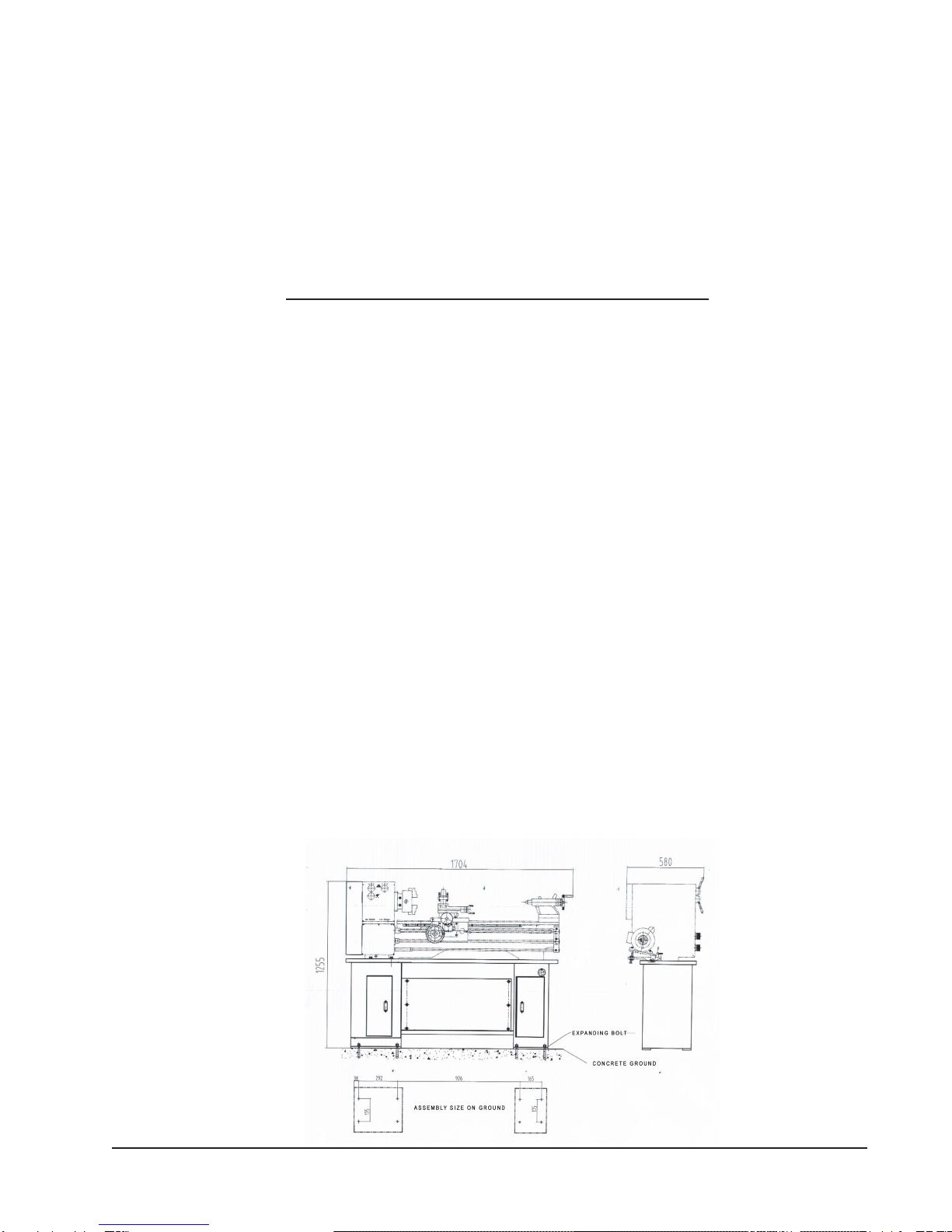
5. Check thelevelof themachine.Using aspiritlevel, check tobe sure thatthebed ofthelathe
islevel bothhorizontallyand frontto back.Ifthere isany outoflevel, correctit now.
Dependingonyourinstallation,useangledironlevelers(shims)toadjustthemachine intoexact
levelfrontto back andsideto side. Checkbothends of thetoolbefore being satisfied.
Besurethemachineislevel,positionedsolidly,andisresistanttovibration.
6. Fasten thelatheto theStandandthe Lathe’soiltray byinsertinga bolt througha lock washerfrom the
insideofthe Stand andupwardthrough theoiltray andlathe.Fasten with awasher and nut.
Repeat thisforeachofthefourmountingholesintheheadstock, andboth mountingholesin
thetailstock.Tightensecurely.Recheckandreadjustlevelifrequired.
NOTE: Periodically recheck the level of the machine to assure that it remains level while it is in use.

Page 6 SKU # 95647
Part
No. Description Qty.
1 Headstock Stand 1
2 Headstock Connecting Strip 1
3 Nut M6 6
4 Connecting Plate between
Stands 1
5 Flat Washer 6 12
6 Bolt M6x10 12
7* Tray* 1
8 Flat Washer 6
9 Spring Washer 6
10 Bolt M12x50 6
11 Tailstock Stand 1
12 Tailstock Connecting Strip 1
Stand Parts List
PLEASE READ THE FOLLOWING CAREFULLY
THE MANUFACTURER AND/OR DISTRIBUTOR HAS PROVIDED THE PARTS DIAGRAM IN THIS
MANUALAS A REFERENCE TOOL ONLY: NETHER THE MANUFACTURER NOR DISTRIBUTOR
MAKES ANY REPRESENTATION OR WARRANTY OF ANY KIND TO THE BUYER THAT HE OR SHE
IS QUALIFIED TO MAKE ANY REPAIRS TO THE PRODUCT OR THAT HE OR SHE IS QUALIFIED TO
REPLACE ANY PARTS OF THE PRODUCT: IN FACT THE MANUFACTURER A ND/OR DISTRIBUTOR
EXPRESSLY STATES THATALL REPAIRS AND PARTS REPLACEMENTS SHOULD BE UNDERTAKEN
BY CERTIFIED AND LICENSED TECHNICIANS AND NOT BY THE BUYER. THE BUYER ASSUMES
ALL RISK AND LIABILITY ARISING OUT OF HIS OR HER REPAIRS TO THE ORIGINAL PRODUCT
OR REPLACEMENT PARTS THERETO, OR ARISING OUT OF HIS OR HER INSTALLATION OF RE-
PLACEMENT PARTS THERETO.
*Please Note: Part 7 (Tray) is not included with the Stand, but with the
43681 Gap Bed Lathe.

Page 7 SKU # 95647
Please note: Oil tray is not included
with Stand. It is a part of the 43681
Lathe
12 11

Harbor Freight Tools Co.makes every effort to assure that its products meet high quality and durability standards,
and warrants to the original purchaser for a period of ninety days from date of purchase that the motor/engine, the
belts (if so equipped), and the blades (if so equipped) are free of defects in materials and workmanship. Harbor
Freight Tools also warrants to the original purchaser, for a period of one year from date of purchase, that all other
parts and components of the product are free from defects in materials and workmanship.This warranty does not
apply to damage due directly or indirectly to misuse, abuse, negligence or accidents; repairs or alterations outside
our facilities; or to lack of maintenance.We shall in no event be liable for death, injuries to persons or property, or
for incidental, contingent, special or consequential damages arising from the use of our product. Some states do
not allow the exclusion or limitation of incidental or consequential damages, so the above limitation of exclusion
may not apply to you. THIS WARRANTY IS EXPRESSLY IN LIEU OF ALL OTHER WARRANTIES, EXPRESS
OR IMPLIED, INCLUDING THE WARRANTIES OF MERCHANTABILITY AND FITNESS.
To take advantage of this warranty, the product or part must be returned to us with transportation charges prepaid.
Proof of purchase date and an explanation of the complaint must accompany the merchandise. If our inspection
verifies the defect, we will either repair or replace the product at our election or we may elect to refund the purchase
price if we cannot readily and quickly provide you with a replacement. We will return repaired products at our
expense, but if we determine there is no defect, or that the defect resulted from causes not within the scope of
our warranty, then you must bear the cost of returning the product.
This warranty gives you specific legal rights and you may also have other rights which vary from state to state.
3491 Mission Oaks Blvd. • PO Box 6009 • Camarillo, CA 93011 • (800) 444-3353
LIMITED 90 DAY/1 YEAR WARRANTY
WARRANTY
Page 8 SKU # 95647
Table of contents
Other Central Machinery Lathe manuals

Central Machinery
Central Machinery CENTRAL MACHINERY 65345 Installation manual

Central Machinery
Central Machinery 98676 Installation manual

Central Machinery
Central Machinery CENTRAL MACHINERY 44859 User manual

Central Machinery
Central Machinery 03173 User manual

Central Machinery
Central Machinery 90692 User manual

Central Machinery
Central Machinery CENTRAL MACHINERY 45861 Installation manual

Central Machinery
Central Machinery MINI BENCH 4019 User manual

Central Machinery
Central Machinery 33684 User manual

Central Machinery
Central Machinery 4019 User manual

Central Machinery
Central Machinery 93212 User manual