Central Pneumatic Professional 96100 Parts list manual

ANGLE GRINDER
7”WIDE - WATER FEED
Model
96100
ASSEMBLY AND OPERATION INSTRUCTIONS
Due to continuing improvements, actual product may differ slightly from the product described herein.
®
3491 Mission Oaks Blvd., Camarillo, CA 93011
Visit our website at: http://www.harborfreight.com
TO PREVENT SERIOUS INJURY, READ AND UNDERSTAND
ALL WARNINGS AND INSTRUCTIONS BEFORE USE.
Copyright©2007 by Harbor Freight Tools®. All rights reserved. No portion of this
manual or any artwork contained herein may be reproduced in any shape or form
without the express written consent of Harbor Freight Tools.
For technical questions or replacement parts, please call 1-800-444-3353.

Page 2SKU 96100 For technical questions, please call 1-800-444-3353.
SPECIFICATIONS
Grinder Head Angle 90 Degrees
Maximum Wheel Diameter 7”
Arbor Diameter 7/8”
Maximum Rated Pressure 90 PSI
Average Air Consumption 5.3 CFM
Maximum RPM 7,500
Air Inlet Size 1/4”-18 NPT
Water Hose Connection 1/4” Barbed Hose Fitting
Dimensions 12-1/4”L x 7-3/8”W x 5-3/16”H
Accessories Spindle Wrench (Qty. 1) / Axle Wrench (Qty. 1)
Auxiliary Side Handle (Qty. 1) / Rubber Bushings (Qty. 3)
4-1/2” Diameter Steel Turbo Diamond Cutting Wheel (Qty. 1)
Weight 8.0 Lb.
SAVE THIS MANUAL
You will need this manual for the safety warnings and precautions, assembly, oper-
ating, inspection, maintenance and cleaning procedures, parts list and assembly diagram.
Keep your invoice with this manual. Write the invoice number on the inside of the front
cover. Keep this manual and invoice in a safe and dry place for future reference.
GENERAL SAFETY RULES AND PRECAUTIONS
WARNING!
READ AND UNDERSTAND ALL INSTRUCTIONS
Failure to follow all instructions listed below may result in
electric shock, fire, and/or serious injury.
SAVE THESE INSTRUCTIONS
WORK AREA
Keep your work area clean and well lit.1. Cluttered benches and dark areas invite
accidents.
Do not operate power tools in explosive atmospheres, such as in the presence2.
of flammable liquids, gases, or dust. Power tools create sparks which may ignite
the dust or fumes.
Keep bystanders, children, and visitors away while operating a power tool.3.
Distractions can cause you to lose control. Protect others in the work area from
debris such as chips and sparks. Provide barriers or shields as needed. Children
should not be allowed in the work area.
REV 07l

Page 3SKU 96100 For technical questions, please call 1-800-444-3353.
PERSONAL SAFETY
Stay alert. Watch what you are doing, and use common sense when operating1.
an air tool. Do not use an air tool while tired or under the influence of drugs,
alcohol, or medication. A moment of inattention while operating power tools may
result in serious personal injury.
Dress properly. Do not wear loose clothing or jewelry. Contain long hair.2.
Keep your hair, clothing, and gloves away from moving parts. Loose clothes,
jewelry, or long hair can be caught in moving parts.
Avoid accidental starting. Make3. sure the Angle Grinder is disconnected from
its water and air supply hoses and all air pressure within the tool is safely
released before performing any service, maintenance, or cleaning procedures
on the tool.
Remove adjusting keys or wrenches before turning the Angle Grinder on.4. A
wrench or a key that is left attached to a rotating part of the tool may result in per-
sonal injury.
Do not overreach. Keep proper footing and balance at all times.5. Proper footing
and balance enables better control of the Angle Grinder in unexpected situations.
Use safety equipment. Always wear eye protection.6. Always wear ANSI-approved
safety impact glasses and hearing protection under a full face shield during use.
TOOL USE AND CARE
Do not force the tool. Use the correct tool for your application.1. The correct
tool will do the job better and safer at the rate for which it is designed.
Do not use the Angle Grinder if the air regulator does not stop flow of air2.
completely.
Store idle tools out of reach of children and other untrained persons.3. Tools
are dangerous in the hands of untrained users.
Maintain tools with care.4. Properly maintained tools are less likely to bind and are
easier to control. Do not use a damaged tool. Tag damaged tools “Do not use”
until repaired.
Check for misalignment or binding of moving parts, breakage of parts, and any5.
other condition that may affect the tool’s operation. If damaged, have the tool
serviced before using. Many accidents are caused by poorly maintained tools.
Use only accessories that are recommended by the manufacturer for your6.
model. Accessories that may be suitable for one tool may become hazardous
when used on another tool.
SERVICE
Tool service must be performed only by qualified repair personnel.1. Service or
maintenance performed by unqualified personnel could result in a risk of injury.

Page 4SKU 96100 For technical questions, please call 1-800-444-3353.
When servicing a tool, use only identical replacement parts. Follow instruc-2.
tions in the “Inspection, Maintenance, And Cleaning” section of this manual.
Use of unauthorized parts or failure to follow maintenance instructions may create
a risk of electric shock or injury.
SPECIFIC SAFETY RULES AND PRECAUTIONS
Maintain labels and nameplates on the Angle Grinder.1. These carry important
information. If unreadable or missing, contact Harbor Freight Tools for a replace-
ment.
Never leave the Angle Grinder unattended when it is connected to its air sup-2.
ply hose (not included) and running. Turn off the air compressor, and disconnect
the air hose before leaving.
Do not allow children and other unauthorized people to handle or play with3.
the Angle Grinder.
Make sure to attach the Side Handle (28) when operating the Angle Grinder.4.
When using a hand-held power tool, always maintain a firm grip on the tool with
both hands.
Only use steel turbo diamond grinding wheels up to 7” diameter and rated at5.
maximum 7,500 RPM.
Always use the Wheel Guard (35) with the Angle Grinder.6. The Guard protects
the operator from wheel fragments.
Never lay the Angle Grinder down until the rotating cutting wheel has come7.
to a complete stop. The rotating cutting wheel can bite on the surface and pull
the tool out of your hands.
Always keep your hands and fingers away from the cutting area and rotating8.
cutting wheel.
Before using the Angle Grinder, always check to make sure the cutting wheel9.
is properly mounted and is not cracked or damaged.
Compressed air only.10. Use clean, dry, regulated, compressed air at 90 PSI. Never
use oxygen, carbon dioxide, combustible gases, or any other bottled gas as a power
source for this tool.
Avoid accidental injury.11. Always wear heavy duty work gloves when changing the
cutting wheel.
WARNING!12. The brass components of this product contain lead, a chemical known
to the State of California to cause birth defects (or other reproductive harm). (Cali-
fornia Health & Safety code § 25249.5, et seq.)
Some dust created by power sanding, sawing, grinding, drilling, and other construc-
tion activities, contains chemicals known [to the State of California] to cause cancer,
birth defects or other reproductive harm. Some examples of these chemicals are:
Lead from lead-based paints
Crystalline silica from bricks and cement or other masonry products

Page 5SKU 96100 For technical questions, please call 1-800-444-3353.
Arsenic and chromium from chemically treated lumber
Your risk from these exposures varies, depending on how often you do this type of
work. To reduce your exposure to these chemicals: work in a well ventilated area,
and work with approved safety equipment, such as those dust masks that are spe-
cially designed to filter out microscopic particles. (California Health & Safety Code
§ 25249.5, et seq.)
WARNING!13. The warnings and precautions discussed in this manual cannot cover
all possible conditions and situations that may occur. It must be understood by the
operator that common sense and caution are factors which cannot be built into this
product, but must be supplied by the operator.
UNPACKING
When unpacking, check to make sure all the parts shown on the Parts List in this
manual are included. If any parts are missing or broken, please call Harbor Freight Tools
at the number shown on the cover of this manual as soon as possible.
ASSEMBLY INSTRUCTIONS
TO
ANGLE
GRINDER
FIGURE A
1. To extend the life of the Angle Grinder, it is recommended that you install an oiler and
water filter in-line with the air outlet valve of the air compressor. (See Figure A.)
SIDE HANDLE (28)
FIGURE B
2. To attach the Side Handle (28), firmly screw the threaded portion of the Side Handle
into the left or right side of the Front Housing (22). (See Figure B.)

Page 6SKU 96100 For technical questions, please call 1-800-444-3353.
GRINDING WHEEL (44)
BUSHING (45)
PRESSURE PLATE (34)
PRESSURE PLATE WRENCH (40)
SPINDLE WRENCH (41)
SPINDLE (33)
FIGURE C
3. To install the Grinding Wheel (44), use the provided Spindle Wrench (41) to hold
the Spindle (33) in place while unscrewing and removing the Pressure Plate (34)
with the Pressure Plate Wrench (40). (See Figure C.)
Insert the Grinding Wheel (44) onto the Spindle (33). Then again use the Spindle4.
Wrench to hold the Spindle in place while firmly screwing the Pressure Plate back
onto the Spindle with the Spindle Wrench (41). (See Figure C.)
NOTE:5. The Angle Grinder comes equipped with 3 thicknesses of Bushings (45) to
accommodate other types of Grinding Wheel being installed. (The included Wheel
does not require a Bushing.) To install a Bushing, insert the Grinding Wheel (44)
onto the Spindle (33). Insert the proper Bushing onto the Spindle. Then secure
the Grinding Wheel and Bushing in place by tightening the Pressure Plate (34).
(See Figure C.)
FIGURE D
WATER VALVE (1)
QUICK
CONNECTOR
(NOT INCLUDED)
AIR REGULATOR (6)
GRINDING WHEEL (44)
6. Check to make sure the Air Regulator (6) on the Angle Grinder is in the closed
position (turn the air regulator counter clockwise) and that your air compressor is
off. Then, connect the compressor’s air supply hose to the Angle Grinder’s Quick
Connector (46). (See Figure D.)
Check to make sure your water supply faucet is7. closed. Then connect the faucet’s
water hose to the Angle Grinder’s Water Valve (1), using an Adapter (not included)
for a typical garden water hose. IMPORTANT: Use only cold, clean water.

Page 7SKU 96100 For technical questions, please call 1-800-444-3353.
OPERATING INSTRUCTIONS
WARNING! Always wear ANSI-approved safety impact glasses under a full1.
face shield and heavy duty work gloves when operating the Angle Grinder.
Check to make sure the Air Regulator (6) and Water Valve (1) on the Angle Grinder2.
are closed. (See Figure D.)
Turn on the air compressor, and set its regulator at no more than 90 PSI. Then al-3.
low sufficient time for the air compressor to reach 90 PSI.
CAUTION! Do not exceed 90 PSI.
Fully open the water supply faucet. Then open the Water Valve (1) on the Angle4.
Grinder, and adjust the Water Valve to obtain the desired flow rate of water from the
tool onto the surface that is to be ground. (See Figure D.)
Make sure to grip the Angle Grinder firmly with both hands at all times when using5.
the Angle Grinder.
The Air Regulator (6) on the Angle Grinder allows the operator to run the tool at6.
variable speeds (from 0 to 7,500 RPM). Open the Air Regulator until you reach the
speed at which you wish to operate the Angle Grinder. (See Figure D.)
Hold the Angle Grinder at an angle of 10 degrees to 15 degrees to the work surface.7.
When only the outer edge of the Grinding Wheel (44) is used, a rough cut surface
will result. If the Grinding Wheel is pressed flat against the work surface, the grind-
ing action will be irregular or bumpy and the tool will be difficult to control.
Do not force the Grinding Wheel (44) into the work surface. Apply moderate pres-8.
sure only. (See Figure D.)
After the grinding job is completed, close the Air Regulator (6) (by turning it counter9.
clockwise) and Water Valve (1) on the Air Grinder. Then turn off the air compressor
and close the water supply faucet. (See Figure D.)
Open the Air Regulator (6) fully by turning it clockwise to release any remaining10.
compressed air from the Air Grinder. Then disconnect the compressor’s air supply
hose and the water supply hose from the tool. (See Figure D.)
Make sure to store the Air Grinder in a clean, dry, safe location out of reach of chil-11.
dren and other unauthorized people.
Prior to use, the Angle Grinder requires the attachment of a8. Quick Connector (not
included) into its Air Inlet (1). To do so, wrap approximately 3” of pipe thread sealer
tape (not included) around the male threads of the Quick Connector. Then firmly
tighten the Quick Connector into the Air Inlet. (See Figure D.)

Page 8SKU 96100 For technical questions, please call 1-800-444-3353.
INSPECTION, MAINTENANCE, AND CLEANING
WARNING!1. Make sure the air supply hose and water hose are disconnected from
the Angle Grinder before performing any inspection, maintenance, cleaning proce-
dures, or leaving it unattended.
Before each use,2. inspect the general condition of the Air Grinder. Check for loose
screws, misalignment or binding of moving parts (by rotating the wheel manually),
cracked or broken parts, damaged Cutting Wheel, loose air/water fittings, and any
other condition that may affect the safe operation of the Grinder. If abnormal noise
or vibration occurs, have the problem corrected before further use.
Do not use damaged equipment.
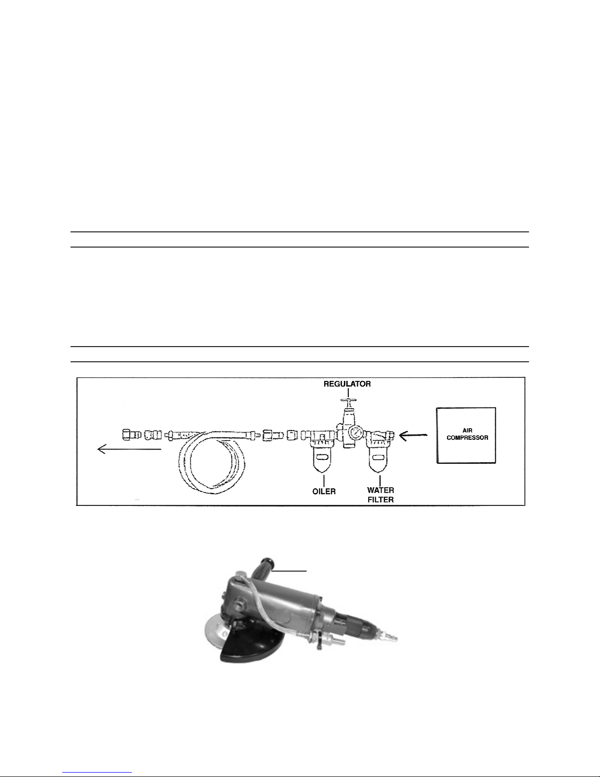
Before each use,3. rotate the Air Regulator counter clockwise to the shut position.
With the compressor in the off position, and the air supply valve in a closed position,
attach the air hose to the inlet connector. With the water valve in a closed position,
and the water tap closed, attach the water supply hose to the water valve. Open
the water supply to the Grinder, and then open the air supply valve from the com-
pressor. Briefly run the unit. Should you feel any vibration or hear any abnormal
noise, or see any water leakage from the clear water supply tube, abruptly turn the
unit off by disconnecting the air supply hose from the unit, shut the water supply
valve, and disconnect the air and water supply hoses, and have the unit serviced
by a qualified technician.
To clean,4. use a clean cloth and mild detergent. Then, dry. Do not use solvents.
Do not immerse the Angle Grinder in liquid.
CAUTION! All maintenance, service, or repairs not mentioned in this manual5.
must only be performed by a qualified service technician.
TROUBLESHOOTING
Problem Possible Cause Possible Solution
Tool does not run at normal
speed.
Not enough air supply.1.
Air Regulator closed.2.
Air supply connection loose.3.
Lack of lubrication.4.
Bearings and/or O-Rings worn out.5.
Adjust compressor regulator to 90 PSI.1.
Open Air Regulator.2.
Secure air supply connection.3.
Make sure an in-line oiler is installed in air4.
supply line.
Have a qualified service technician replace5.
Bearings and/or O-Rings.
Automatically starts when
connected to air supply.
Air Regulator open. Close Air Regulator.
Abnormal vibration. Housing
overheats.
Rotor Blades broken or worn out. Have a qualified service technician replace Rotor
Blades.
Poor cutting quality. Dull or defective Cutting Wheel. Replace Cutting Wheel.

Page 9SKU 96100 For technical questions, please call 1-800-444-3353.
PARTS LIST AND ASSEMBLY DIAGRAM
Part Description Qty.
1 Water Valve 1
2 Screw 4
3 Cushion 1
4 Nut 1
5 Air Inlet Connector 1
6 Air Regulator 1
7 O-Ring 4
8 Fixing Bolt 1
9 Rear Base 1
10 Rear Housing 1
11 Regulator 1
12 Bearing 1
13 Rear Plate 1
14 Cylinder Fixing Bolt 1
15 Cylinder 1
Part Description Qty.
16 Rotor Blade 4
17 Rotor 1
18 Front Plate 1
19 Bearing 1
20 Major Gear 1
21 Paper Cushion 1
22 Front Housing 1
23 Water Connector 1
24 O-Ring 1
25 Bearing 1
26 Fixing Spring 1
27 Screw 1
28 Side Handle 1
29 Riffle Cushion 1
30 Minor Gear 1
Part Description Qty.
31 Bearing 1
32 Semi-Round Key 1
33 Spindle 1
34 Pressure Plate 1
35 Wheel Guard 1
36 Screw 4
37 Rear Retainer 1
38 Front Retainer 1
39 Water Diverter 1
40 Pressure Plate Wrench 1
41 Spindle Wrench 1
42 Water Pipe 1
43 Muffler 1
44 Cutting Wheel 1
45 Bushing 3
Cutting Wheel (44) not shown.
Bushings (45) not shown.
Note: Some parts are listed and shown for illustration purposes only, and are not available
individually as replacement parts.

Page 10SKU 96100 For technical questions, please call 1-800-444-3353.
PLEASE READ THE FOLLOWING CAREFULLY
THE MANUFACTURER AND/OR DISTRIBUTOR HAS PROVIDED THE PARTS LIST AND ASSEMBLY
DIAGRAM IN THIS MANUAL AS A REFERENCE TOOL ONLY. NEITHER THE MANUFACTURER OR
DISTRIBUTOR MAKES ANY REPRESENTATION OR WARRANTY OF ANY KIND TO THE BUYER THAT HE
OR SHE IS QUALIFIED TO REPLACE ANY PARTS OF THE PRODUCT. IN FACT, THE MANUFACTURER
AND/OR DISTRIBUTOR EXPRESSLY STATES THAT ALL REPAIRS AND PARTS REPLACEMENTS
SHOULD BE UNDERTAKEN BY CERTIFIED AND LICENSED TECHNICIANS, AND NOT BY THE BUYER.
THE BUYER ASSUMES ALL RISKS AND LIABILITY ARISING OUT OF HIS OR HER REPAIRS TO THE
ORIGINAL PRODUCT OR REPLACEMENT PARTS THERETO, OR ARISING OUT OF HIS OR HER
INSTALLATION OF REPLACEMENT PARTS THERETO.
LIMITED 1 YEAR / 90 DAY WARRANTY
Harbor Freight Tools Co. makes every effort to assure that its products meet high
quality and durability standards, and warrants to the original purchaser that for a period of
one year from date of purchase that the tank is free of defects in materials and workman-
ship (90 days if used by a professional contractor or if used as rental equipment). Harbor
Freight Tools also warrants to the original purchaser, for a period of ninety days from date
of purchase, that all other parts and components of the product are free from defects
in materials and workmanship. This warranty does not apply to damage due directly or
indirectly to misuse, abuse, negligence or accidents, repairs or alterations outside our fa-
cilities, normal wear and tear, or to lack of maintenance. We shall in no event be liable for
death, injuries to persons or property, or for incidental, contingent, special or consequential
damages arising from the use of our product. Some states do not allow the exclusion or
limitation of incidental or consequential damages, so the above limitation of exclusion may
not apply to you. THIS WARRANTY IS EXPRESSLY IN LIEU OF ALL OTHER WARRAN-
TIES, EXPRESS OR IMPLIED, INCLUDING THE WARRANTIES OF MERCHANTABILITY
AND FITNESS.
To take advantage of this warranty, the product or part must be returned to us with
transportation charges prepaid. Proof of purchase date and an explanation of the com-
plaint must accompany the merchandise. If our inspection verifies the defect, we will either
repair or replace the product at our election or we may elect to refund the purchase price
if we cannot readily and quickly provide you with a replacement. We will return repaired
products at our expense, but if we determine there is no defect, or that the defect resulted
from causes not within the scope of our warranty, then you must bear the cost of returning
the product.
This warranty gives you specific legal rights and you may also have other rights
which vary from state to state.
3491 Mission Oaks Blvd. • PO Box 6009 • Camarillo, CA 93011 • (800) 444-3353
Table of contents
Popular Grinder manuals by other brands

Parkside
Parkside PDWS 125 A1 Translation of the original instructions

Black & Decker
Black & Decker KG1202 Original instructions

Metabo
Metabo W 7-100 Instructions for use

Ingersoll-Rand
Ingersoll-Rand 344MAX Series Product information

Dynabrade
Dynabrade 47200 Safety, operation and maintenance manual

RODCRAFT
RODCRAFT RC7091 operating instructions

Universal Tool
Universal Tool UT8775-1 General Safety Information & Replacement Parts

Speedaire
Speedaire 5YAR8 Operating instructions & parts manual

Predator
Predator PD23.2 User & Safety Instructions

Amano
Amano Pioneer Eclipse PE225GP Operator's manual

Metabo
Metabo WPB 36 LTX BL 230 Original operating instructions

EINHELL
EINHELL TP-AG 1275 operating instructions