Centrica Panoramic Power Manual

Panoramic Power
Modbus TCP Programmer’s Guide
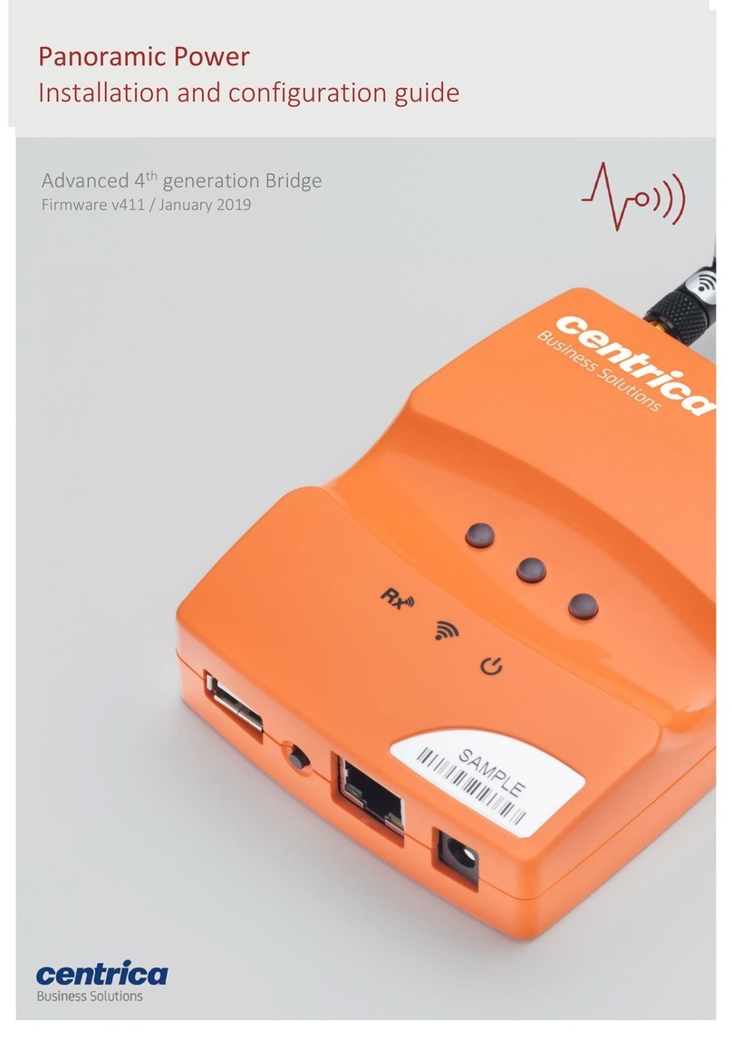
Gen 4/4+ Bridge
Firmware v476 / February 2022

2
Contents
Introduction and overview ............................................................................................................ 3
Hardware & Networking requirements ........................................................................................ 4
Supported Hardware ................................................................................................................................. 4
Supported LAN networks ........................................................................................................................... 4
Assigning a fixed Bridge IP address ........................................................................................................... 4
Assigning a Slave address .......................................................................................................................... 4
Bridge configuration .................................................................................................................................. 4
NTP requirements ...................................................................................................................................... 5
Modbus parameters .................................................................................................................................. 5
Bridge Modbus Software Model ................................................................................................... 6
Modbus Register Map ............................................................................................................................... 6
Sensor slot allocation example .................................................................................................................. 9
Sensor Readings ...................................................................................................................................... 10
Pulse counter registers ........................................................................................................................... 11
Sensor Calibration keys (not PAN42) .......................................................................................... 12
Bridge Configuration for stand-alone mode ............................................................................... 12
Connect to the Bridge web interface ..................................................................................................... 12
Set networking mode ............................................................................................................................. 13
Set Connection mode ............................................................................................................................. 14
Define Bridge UI accessibility .................................................................................................................. 15
Assign sensors to slots ............................................................................................................................ 16
Delete a sensor from the list .................................................................................................................. 18
View Sensor Readings ............................................................................................................................. 19
Configure the Bridge Pulse interface .......................................................................................... 21
Bridge LED configuration for stand-alone modes ...................................................................... 22
Figure Li
s
t
Figure 1: Network diagram ________________________________________________________________ 3
Figure 2: Software model example __________________________________________________________ 9
Figure 3: Sensor data storage _____________________________________________________________ 10
Figure 4: The Network Setup Screen ________________________________________________________ 13
Figure 5: The Connection Setup Screen ______________________________________________________ 14
Figure 6: Bridge Configuration ____________________________________________________________ 15
Figure 7: The Sensors Tab ________________________________________________________________ 16
Figure 8: The Sensor type select menu ______________________________________________________ 17
Figure 9: Add Sensor Pop-up ______________________________________________________________ 17
Figure 10: Add PAN42 Sensor Pop-up _______________________________________________________ 18
Figure 11: Sensor’s list – Main values _______________________________________________________ 19
Figure 12: Sensor’s list – Additional readings _________________________________________________ 20
Figure 13: Pulse Setup Tab _______________________________________________________________ 21

3
Introduction and overview
This document covers the operation and interface definition of the Panoramic Power Bridge when
working in the stand-alone mode. In this mode, the Bridge implements a Modbus TCP/RTU
protocol which sends sensor’s current readings to a local server. The local server acts as a Modbus
master server and the Bridge acts as a Modbus TCP/RTU slave.
This guide focuses on the new Bridge stand-alone (Modbus TCP/RTU) operational mode. It is
supplementary to the Gen 4+ Bridge Manual which covers basic Bridge operations and should be
reviewed prior to using this guide. Version 476 adds support for PAN42 sensors (up to 3) and for
Modbus RTU (RS485) connection.
The image below depicts a typical network diagram for a Bridge operating in the stand-alone
mode:
• Sensors transmit readings once every 10 seconds to the Bridge via proprietary wireless
communications.
• For each configured sensor, the Bridge stores the last received measurement in memory. It
will be stored until overridden by a new measurement from the same sensor or until the
Bridge resets.
• A Modbus TCP/RTU master device (typically a computer or PLC) connects to the Bridge via
local area network (LAN) or RS485 cable and polls the Bridges for sensor data.
• The Modbus master device can connect to multiple Bridges, each of them receiving
multiple sensors.
• Bridge configuration is done via the Bridge’s built in web server, using the web browser of
a laptop connected in the LAN.
Figure 1: Network diagram

4
Hardware & Networking requirements
Supported Hardware
• Sensors: PAN10, PAN12, PAN14 and PAN42.
• The Modbus interface also supports reading the Bridge’s pulse inputs (Gen4 and above)
• The Modbus TCP solution is supported by Gen3 and above and requires firmware v470 or
higher. To support PAN42 sensors, and/or RTU interface, firmware v476 is needed.
• In stand-alone mode, each Bridge supports up to 32 data points (A single phase sensor or a
phase in a 3-phase sensor).
Supported LAN networks
To work in the Modbus TCP mode, the Bridge must be set-up for Ethernet or Wi-Fi network
connectivity. A Bridge configured for cellular network connectivity supports Modbus RTU but does
not support Modbus TCP.
Assigning a fixed Bridge IP address
For Modbus TCP to operate properly, the Modbus master must be able to repeatedly reach a
specific Bridge via its IP address or DNS name. The solution requires a fixed static IP address
assigned to the Bridge. This can be done by selecting ‘fixed IP’ in the Bridge network settings, or
alternatively using DHCP but ensuring that the DHCP server always assigns the same IP address to
the specific Bridge.
Please refer to the Gen 4+ Bridge Manual for more information about configuring the Bridge
networking.
Assigning a Slave address
For Modbus RTU to operate properly, the Bridge is assigned a Base (slave) Address and the
Modbus master must have a list of all the monitored Bridges and their Base Addresses (in the
range of 1 to 247).
Bridge configuration
Bridge configuration is done from a laptop’s web browser using the Bridge built-in web server.
Initial Bridge configuration, including setting up a fixed IP address to be used later, is done via a
directly connected laptop. Please see ‘Accessing the Bridge web interface’ section in the Gen 4+
Bridge Manual.
Once a fixed IP has been assigned to the Bridge and the
Bridge Admin UI Availability
in the
Bridge
Configuration
screen is set to
Always
, further configuration can be done by navigating to the Bridge
IP address from a web browser. The laptop used for such configuration must have HTTP route to
the Bridge.

5
NTP requirements
To operate properly, the Bridge needs to get the real time clock (RTC). Since the Bridge has no
battery-powered hardware RTC, it gets the time using a standard NTP server.
The Bridge gets the NTP time, as part of the boot process, using the following process:
1. If a dedicated NTP server IP is defined, it will try to get the time from that server
2. Alternatively, it will try to get the time from a list of well-known public NTP servers
3. If both options above fail, it will get the time from PowerRadar.
Option 3 above only works in ‘PowerRadar connected mode’ or ‘combined mode’ (See ‘Connection
Setup’ section below). Therefore, when working in ‘Stand-Alone Modbus TCP’ mode an NTP server
must be defined in the LAN or alternatively, NTP outbound access to public servers must be
implemented in the firewall.
Another option is to set the real-time clock via the Modbus Interface (by writing to registers 1-2.
see Table 1). This will override any time retrieved during the boot process.
Modbus parameters
These parameters are needed when setting up the connection from the Modbus Master:
• The Bridge Modbus TCP interface is enabled via
TCP port 502
• Recommended timeout value for the Master is
5 seconds
.
•
Little endian
word order is used
• For
Modbus RTU
mode an RS485 interface set to
38400 Baud, 8 data bits, No parity, one
Stop bit
and
no handshake
(No DSR, CTS, DTR, RTS). Request messages can get Responses
of up to 125 data registers. See the Gen 4+ Bridge Manual for details of the Bridge Modbus
(RS485) connector. Note: A USB to RS485 can be used for the RS485 interface.

6
Bridge Modbus Software Model
Modbus Register Map
This section is for use by the Modbus Host programmer. The table below shows the Bridge register
map as reflected to the Modbus Master:
Type
Functional
Code
Register #
(Dec)
Description
Size (16 bit
words)
Format
Comments
Bridge Date/Time
R/W
Read=3
Write=16
0001-0002
Bridge date and time
(UNIX Epoch time)
2
UINT32
Set through Modbus or by NTP
A UNIX Epoch time is the number of
seconds that have elapsed since 00:00:00
Thursday, 1 January 1970, Coordinated
Universal Time (UTC), minus leap seconds.
The consensus is for Epoch time to be
signed, and this is the usual practice.
Nevertheless, it can be used as a 31-bit
unsigned number.
1.
Bridge Information, 10 words (registers)
R
4
0001
Bridge model
1
UINT16
0 - GEN3, 1 - GEN4, 2 - GEN4+,
3 - GEN5, 4 - GEN4+ NW
R
4
0002 - 0003
Bridge serial number
2
UINT32
R
4
0004
Bridge mode
1
UINT16
0 – Connect to PowerRadar,
1 - Standalone, 2 - Combined
R
4
0005
Bridge HW version
1
UINT16
R
4
0006
Bridge FW ver. - Major
1
UINT16
R
4
0007
Bridge FW ver. - Minor
1
UINT16
R
4
0008
Bridge Noise Floor [dBm]
1
INT16
R
4
0009-0010
Assigned slots
2
UINT32
Bit field format. One bit per slot.
1st slot in LSBit.
1 – assigned slot, 0 - unassigned
2. Sensor Readings - Array of 32 slots, 20 words (registers) each. The first 9 are common for all sensors. N = Slot No. 0-31
R
4
2001+20N
Sensor status
1
UINT16
0- Slot Empty
1- No message RX
2- Message RX (RX = received)
3- Message RX, No RTC
4- No Messages RX over 1 minute
5- No Messages RX over 5 minutes
See Table 2.
R
4
2002+20N
2003+20N
Sensor S/N
(0: unassigned slot)
2
UINT32
R
4
2004+20N
Sensor Type
and Phase Number
(PAN42)
1
UINT16
In LSByte: Sensor Type
10=PAN10, 12=PAN12, 14=PAN14
For PAN42:
MSByte = Phase No., LSByte = 42
Phase 1: 1, 42 = 298
Phase 2: 2, 42 = 554
Phase 3: 3, 42 = 810
R
4
2005+20N
2006+20N
Unix Epoch Timestamp
(0: RTC not set)
2
UINT32
Timestamp – a UNIX Epoch timestamp of
the latest message received from the
sensor. It is the number of seconds that
have elapsed since 00:00:00 Thursday, 1
January 1970, Coordinated Universal Time
(UTC), minus leap seconds.
The consensus is for Epoch time to be
signed, and this is the usual practice.
Nevertheless, it can be used as a 31-bit
unsigned number.
R
4
2007+20N
2008+20N
Current Reading [A]
2
FLOAT32

7
Type
Functional
Code
Register #
(Dec)
Description
Size (16 bit
words)
Format
Comments
R
4
2009+20N
Reading RSSI [dBm]
1
INT16
R
4
2010+20N
Sensor HW version
1
UINT16
R
4
2011+20N
Sensor FW ver. - Major
1
UINT16
R
4
2012+20N
Sensor FW ver. - Minor
1
UINT16
Next 8 registers are for PAN42 sensors. N = Slot No. 0-31
R
4
2013+20N -
2014+20N
Vs-rms [V]
2
FLOAT32
R
4
2015+20N –
2016+20N
Active Power [Watt]
2
FLOAT32
R
4
2017+20N –
2018+20N
Reactive Power [VAR]
2
FLOAT32
R
4
2019+20N –
2020+20N
Power Factor
2
FLOAT32
3.
Extended parameters - Array of 32 slots x 4 registers each. N = Slot No. 0-31
R
4
3001+4N
additional_idx
1
UINT16
Only for Pan42.
Entry index number +1 of
additional Pan42 data in the
Additional parameters
table (next
table).
Range: 1 – 9. For other sensors = 0.
R
4
3002+4N -
3003+4N
Line frequency [Hz]
2
FLOAT32
For PAN42
R
4
3004+4N
PAN42 Error Report
1
UINT16
PAN42 errors: (see note below)
1 = EEPROPM read error
2 = EEPROPM write error
3 = Energy counter rollover
4 = Energy counter manual reset
4. Additional parameters – Array of 9 slots x 18 registers each (up to 3 PAN42). n= additional_idx-1 of Slot N (N= Slot No. 0-31)
R
4
3501+18n
Report flags
1
UINT16
For future use
R
4
3502+18n
spare
1
UINT16
For future use
R
4
3503+18n -
3504+18n
Active Energy – Phase #X
[Watt-hr]
2
FLOAT32
Phase Consumed Active Energy
R
4
3505+18n -
3506+18n
Exported active energy –
Phase #X [Watt-hr]
2
FLOAT32
Phase Exported Active Energy
R
4
3507+18n -
3508+18n
V_THD – Phase #X [%]
2
FLOAT32
Phase Voltage THD
R
4
3509+18n -
3510+18n
I_THD – Phase #X [%]
2
FLOAT32
Phase Current THD
R
4
3511+18n
SAG condition – Phase #X
1
UINT16
Phase SAG events count in last
minute
R
4
3512+18n
SAG duration - Phase #X
1
UINT16
Phase SAG events duration (msec)
in last minute
R
4
3513+18n -
3514+18n
Phase Balance [degrees]
2
FLOAT32
in Ph1: Ph1-Ph3; in Ph2: Ph2-Ph1;
in Ph3: Ph3-Ph2
R
4
3515+18n
SWELL condition - Phase
#X
1
UINT16
Phase SWELL events count in last
minute
R
4
3516+18n
SWELL duration - Phase
#X
1
UINT16
Phase SWELL events duration
(msec) in last minute

8
Type
Functional
Code
Register #
(Dec)
Description
Size (16 bit
words)
Format
Comments
R
4
3517+18n -
3518+18n
Unix Epoch SAG / SWELL
Event Timestamp
(0: There was no event
or RTC not set)
2
UINT32
Event Timestamp – Timestamp of
the latest SAG / SWELL event
message received from the sensor.
A UNIX Epoch time is the number of
seconds that have elapsed since 00:00:00
Thursday, 1 January 1970, Coordinated
Universal Time (UTC), minus leap seconds.
The consensus is for Epoch time to be
signed, and this is the usual practice.
Nevertheless, it can be used as a 31-bit
unsigned number.
5. Pulse Counter #1 Readings
R
4
5001
Status
1
UINT16
0- Disabled
1- No pulse received since last
read or reboot
2- Pulse received, No RTC
3- Pulse received, RTC is set
R
4
5002-5003
Unix Epoch Timestamp of
Modbus status read
2
UINT32
(0: RTC not set)
R
4
5004-5005
Count (Pulse #1)
2
UINT32
Accumulated count during the
lifetime of the Bridge.
Note: the bridge counts both rising
and falling edges of the pulses.
6. Pulse Counter #2 Readings
R
4
5006
Status
1
UINT16
0- Disabled
1- No pulse received since last
read or reboot
2- Pulse received, No RTC
3- Pulse received, RTC is set
R
4
5007-5008
Unix Epoch Timestamp of
Modbus status read
2
UINT32
(0: RTC not set)
R
4
5009-5010
Count (Pulse #2)
2
UINT32
Accumulated count during the
lifetime of the Bridge.
Note: the bridge counts both rising
and falling edges of the pulses.
Table 1: Bridge Register Map
Note
: When reading or writing 32-bit elements (UINT32 or FLOAT32), it is required to access them
in a single Modbus commend (with size =2). Accessing them via two separate commands (size=1)
may create abnormal results.
Little endian
Byte swap
word order is used.
The map contains 4 main areas:
•
Bridge date/time settings
– Holding registers 1-2 - This is where the Modbus host can set
or read the
R
eal-
T
ime
C
lock of the Bridge. It can be used if there is no RTC server reachable
by the Bridge.
•
Bridge information
– Input registers 1-12 - Table 1.1 - Various Bridge status data
•
Sensor readings
– This is where the sensor readings are retrieved.
There are 3 tables with sensor readings
: (N = slot number 0 to 31)

9
a. Table 1.2 – Input registers 2001-2010 +20N –
Sensor main readings
– An array of 32
slots x 20.
b. Table 1.3 - Input registers 3001-3004 +4N –
Extended parameters
- Array of 32 slots x 4
registers each
c. Table 1.4 - Input registers 3501-3518 +18n –
Additional parameters
– Array of 9 slots x
18 registers each (for up to 3 PAN42 sensors). Here n = 0-8 (additional_idx–1 from table
1.3)
NOTE: For the additional parameters of a PAN42 sensor, use the additional_idx from
table 1.3 to get the associated entry in table 1.4.
Additional parameters: Table 1.4(n), where n = Table 1.3(additional_idx – 1) (range 0-
8)
•
Pulse Counter #1 and #2 Readings
– These holds the counters for the two pulse inputs of
the Bridge. Tables 1.5 and 1.6 – Input registers 5001-5008 for Pulse counter #1, Input
registers 5009-5016 for Pulse counter #2.
Note: the bridge counts both rising and falling edges of the pulses. It means that for a
device with a KY output, the count should be divided by 2.
•
PAN42 EEPOROM error reports
– The PAN42 uses an EEPROM to save the energy
counters. It saves the counters every 20 seconds. In case of power shortage, when the
power is back, the last saved values are restored. If the reading from the EEPROM or
writing to EEPROM fails, the PAN42 sends an error report (error 1 or 2). The energy
counters roll over when the value exceeds the 32-bits size (0xFFFFFFFF to 0). In this case it
sends an error report 3. The user can reset the counters by pressing an internal
pushbutton (see the PAN-42 User Manual). This action sends the error report 4.
Sensor slot allocation example
The following image depicts an example of how the sensor software model works:
Figure 2: Software model example
In the example above:
• Only two of the 32 Bridge slots have been assigned to sensors.
• Slot #1 has been assigned to sensor S/N 12345678
• Slot #2 has been assigned to sensor S/N 12312312
• Slots #3-#32 have not been assigned with any sensors and remain empty.
• Whenever a sensor message from one of the two sensors (12345678 or 12312312) is
received, the sensor-data section of the table will be updated. The update will override the
previous data.

10
• We can also see another sensor (S/N 55555555) which is received by the Bridge but has
not been allocated to any slot. This sensor data will be ignored when the Bridge is in
Modbus TCP mode.
In ‘PowerRadar connected mode’ or ‘combined mode’ all sensor data is simultaneously sent
to PowerRadar regardless of the assignment.
Sensor Readings
As seen in Figure 2 above, each sensor slot contains sensor data. This section will review and
explain the sensor data stored for each slot.
Figure 3: Sensor data storage
As seen in the image, each sensor slot reserve 40 bytes of memory and store the following values:
•
Status –
Indicating the status of the reading of the specific slot.
•
Sensor S/N
– This is the serial number of the sensor associated with this slot
•
Timestamp
– A UNIX Epoch timestamp of the latest message received from the sensor. It is
the number of seconds that have elapsed since 00:00:00 Thursday, 1 January 1970,
Coordinated Universal Time (UTC), minus leap seconds.
•
Current [A]
– The calibrated current (in A) measured in the last sensor message received.
•
RSSI
– an indication of the RSSI (signal strength) of the last measurement in dBm.
Note
: When reading a specific sensor slot data, it is recommended to read the entire 20-word (40
bytes) slot data using a single Modbus commend (with size =20), then parse the data in the
Modbus master. The maximum number of registers that can be read in one request is 125 (250
Bytes). It means that it is possible to read data of some sensors in one request.

11
When reading the data, the status register should be analyzed first. Based on its content the other
registers should be processed as shown in the table:
Status
Code
Meaning
0
Slot Unassigned
This slot has no sensor S/N allocation. All other registers in this
slot can be ignored.
1
No message was
Received
A sensor S/N has been assigned to this slot, but no sensor
message has been received since the last Bridge reset. This
can be because the sensor is not yet installed, is not in the
Bridge RF coverage area, or because the device monitored by
the sensor is off.
All other registers in this slot can be ignored.
2
Message has been
Received OK
A sensor S/N has been assigned to this slot, and a reading has
been received. The reading timestamp, Current value and RSSI
can be processed.
3
NO RTC
A sensor S/N has been assigned to this slot, and a reading has
been received. However, since the Bridge has no real-time-
clock (RTC) the timestamp value is 0. In this case, the Bridge
RTC clock should be set via the Bridge Date/Time settings
register.
4
No message has been
received for over 1
minute
A sensor S/N has been assigned to this slot, and a reading has
been received. No message has been received for over 1
minute. The reading timestamp, Current value and RSSI are of
the last received message.
5
No message has been
received for over 5
minutes
A sensor S/N has been assigned to this slot, and a reading has
been received. No message has been received for over 5
minutes. The reading timestamp, Current value and RSSI are
of the last received message. The status will change upon
receiving a message or a Bridge reset (after resetting it will be
1 = No Msg Received).
Table 2: Sensor Status
Pulse counter registers
Gen 4 Bridges (and above) support two pulse inputs. The Bridge counts the pulses on each of the
inputs and provides this data in the registers.
Note: The Bridge counts both rising and falling edges of the pulse. These registers store the total
count. This value is persistent even after a Bridge reset.

12
Sensor Calibration keys (not PAN42)
Each Panoramic sensor is calibrated during manufacturing and a unique calibration key is
generated for every sensor. This key is used to calibrate the sensor raw measurements to achieve
optimal accuracy.
When working in PowerRadar mode, raw measurements are calibrated in the cloud. In stand-alone
mode, however, the calibration is done on the Bridge itself, utilizing a unique calibration key.
The calibration key is a sensor specific, 15 alpha-numeric string (e.g. ACD43-XU3V5-Z7RF3), which
must be provided when allocating a sensor to be used in stand-alone mode and dual mode.
To get a calibration key for a specific sensor use one of the flowing options:
•
Automatically calibration key retrieval
- if the laptop used to configure the Bridge has
Internet access, a calibration key can be automatically retrieved when defining the sensor
in the Bridge. This is the easiest and most efficient way to get the calibration key. Internet
access is only required for the laptop used to set the Bridge and only during the
configuration.
•
Manual calibration key retrieval
– In the rare case where internet access is not available
during Bridge configuration, please contact PowerRadar support by opening a ticket at
www.powerradar.energy/support and provide the serial numbers of sensors needed. A file
containing the respective calibration keys will be provided to be manually entered into the
Bridge.
Bridge Configuration for stand-alone mode
To work in the stand alone-mode the Bridge must be configured via the built-in web interface. This
is explained in detail in the Gen 4+ Bridge Manual.
Connect to the Bridge web interface
Initial Bridge configuration is done by forcing the Bridge into configuration mode and directly
connecting a laptop with point-to-point ethernet cable.
The full process is defined in the ‘Accessing the Bridge web interface’ section in the Gen 4+ Bridge
Manual.

13
Set networking mode
1. Navigate to the ‘Network Setup’ tab and set the Bridge networking mode
2. Note that only ‘Ethernet’ and ‘Wi-Fi’ networks support the stand-alone Modbus TCP mode.
Stand-alone Modbus RTU mode can work alongside any network mode.
Note that when ‘Wi-Fi’ network is set, adding sensors in the ‘Sensors’ tab is restricted to 28
sensors.
3. Set the IP configuration for the Bridge. A static IP (or DHCP with fixed IP guarantee) must
be used in stand-alone mode to allow the master Modbus TCP to repeatedly address this
Bridge.
Figure 4: The Network Setup Screen

14
Set Connection mode
1. Navigate to the ‘Connection Setup’ tab to set the Bridge connection preferences.
2. By default, the Bridge is configured to connect to PowerRadar
3. Check ‘Enable Stand Alone Modbus mode’ to enable the Modbus mode option.
4. Check ‘Modbus TCP’ to enable the Modbus TCP option, or ‘Modbus RTU’ to enable the
Modbus RTU option.
5. For the Modbus RTU option, enter the ‘Modbus Base Address’ (1 to 247).
6. Note that it is possible to set both ‘PowerRadar’ and ‘Modbus’ modes concurrently. In this
case:
a. The Bridge will send sensor data to PowerRadar (all received sensors).
b. In parallel, it will make sensor data available for Modbus (allocated sensors only).
Figure 5: The Connection Setup Screen

15
Define Bridge UI accessibility
For enhanced security, the Bridge UI is accessible by default only during configuration mode, using
a wired-connected laptop.
It is possible to change that configuration, making the UI accessible from any laptop in the same
LAN as the Bridge. While less secure, this mode can be useful during testing and sensor setup
when multiple frequent changes are made to the Bridge UI. Setting up a unique administrator
password is strongly recommended.
1. Navigate to the ‘Bridge Configuration’ tab
2. Choose Bridge UI accessibility:
a. Choose ‘Only in config mode’ for maximum security – In this mode the Bridge UI is
only accessible from laptop with direct Ethernet connection and only when the
Bridge is placed in Configuration mode.
b. Choose ‘Always’ for maximum flexibility – In this mode the Bridge UI is available
from any device with Bridge network access. This mode is recommended only
during setup period and after a unique administrator password is set.
Figure 6: Bridge Configuration

16
Assign sensors to slots
Any sensor to be used by the Modbus interface must first be allocated to specific location (slot)
within the Bridge. Once allocated, this sensor readings are guaranteed to always be in a fixed
register address.
Readings from sensors that were not assigned to a slot, will not be provided via the Modbus
interface (but will continue to be sent to PowerRadar if ‘Connect to PowerRadar’ is set in the
connection configuration page).
Figure 7: The Sensors Tab

17
Assign a sensor to a slot
1. Navigate to the ‘Sensors’ tab
2. Choose an empty slot and press the ‘+’ icon. For PAN42 sensor, make sure the following
two slots are also available (PAN42 sensor requires 3 empty consecutive slots).
3. In the popup dialog choose the type of sensor:
4. For PAN10, PAN12 and PAN14:
a. Choose
Sensor
.
b. Type the sensor’s serial number.
c. Type the calibration key if you have it or click ‘Get calibration key’ to have it
automatically retrieved and inserted (PowerRadar web site must be reachable
from the configuration laptop).
d. Press the
Save
button.
Figure 8: The Sensor type select menu
Figure 9: Add Sensor Pop-up

18
5. For PAN42:
a. Type the sensor’s serial number. The sensor is registered in 3 slots (for 3 phases)
b. Press the
Save
button.
The sensor is now assigned to the slot. New readings will be shown in this screen and
made available via the Modbus TCP/RTU interface.
Note 1:
Stand-alone mode supports the following sensor types: PAN10, PAN12, PAN14 and
up to 3 PAN42 sensors.
Note 2:
The calibration key is a unique, per-sensor, value used by the Bridge to calibrate
each reading for accuracy. It is a mandatory, sensor specific, value. PAN42 does not need
calibration.
Note 3:
When clicking ‘Get Key, your browser communicates with PowerRadar to get the
calibration key. It is, therefore, essential that the laptop has Internet connectivity.
Note 4:
If having issues retrieving the calibration key, please contact support who can
provide an offline list of calibration keys to be entered manually.
Note 5:
‘Wi-Fi’ network consumes more memory and adding/deleting sensors in the
‘Sensors’ tab is restricted to 28 sensors (but you can add 32 sensors using the ‘Ethernet’
connection and return to ‘Wi-Fi’ when done).
Delete a sensor from the list
To delete a sensor from the list, press the Trash-Can icon at the beginning of the line. Confirm the
delete.
You can delete a PAN42 sensor by pressing the Trash-Can at any of the 3 sensor lines, all 3 lines will
be deleted.
Figure 10: Add PAN42 Sensor Pop-up

19
View Sensor Readings
Sensor readings are available in the ‘Sensors Tab’. Each allocated sensor will display the last
received reading. A new reading will override the previous reading.
1. Navigate to the ‘Sensors’ tab. This Tab is accessible only when ‘Connection Setup’ > ‘Enable
stand-alone Modbus mode’ is checked.
2. Allocated slots will show the following values for PAN10, PAN12, PAN14 and PAN42:
a.
Sensor S/N
: The serial number of the allocated sensor
b.
Current [A]
: The last calibrated measurement in Ampere.
c.
RSSI [dBm]:
The received signal strength of the last measurement.
d.
Timestamp
: the time of last measurement.
Note 1:
The current readings shown here have already been individually calibrated by the
Bridge for accuracy, using the calibration key.
Note 2:
PAN10 and PAN12 current readings can be used as-is. For PAN14, these values
should be multiplied by the CT-Rate of the CT used.
For PAN42 the table will show the following additional values:
e.
Voltage [V]
: The last measurement in Volts RMS
f.
Active Power [W]
: The last measurement in Watts
g.
Reactive Power [VAR]:
The last measurement in VARs
h.
Power Factor
: The last measurement power factor
i.
Frequency [Hz]
: The last measurement in Hertz
Note 3:
For PAN42 the current, active power and reactive power reading values should be
multiplied by the CT-Rate of the CT used.
Figure 11: Sensor’s list – Main values

20
Scroll Right for additonal readings:
Figure 12: Sensor’s list – Additional readings
Other manuals for Panoramic Power
2
Table of contents
Other Centrica Network Hardware manuals