Centrica Panoramic Power Series Operator's manual

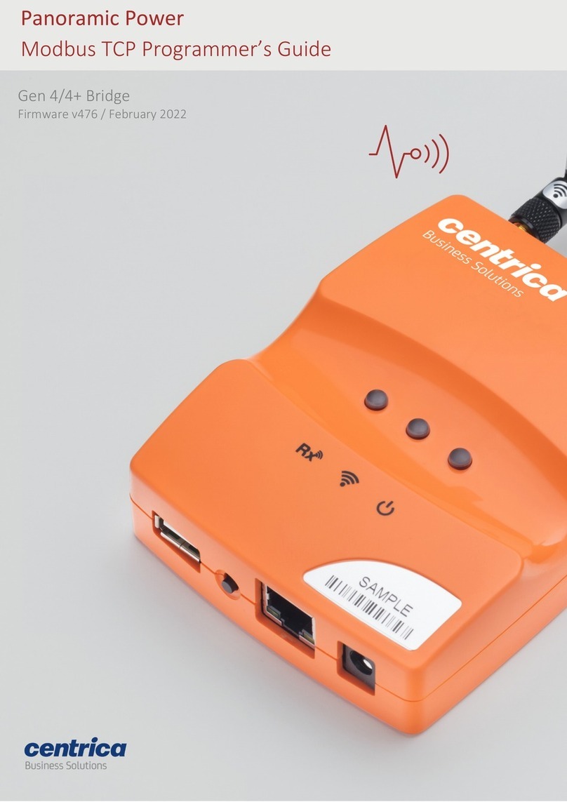
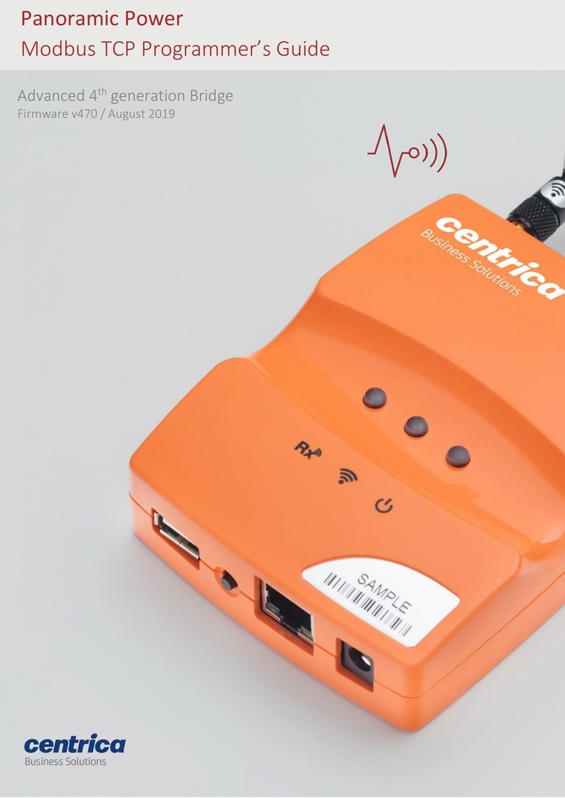
Advanced 4th generation Bridge
Firmware v470 / August 2019
Panoramic Power
Installation and configuration guide

2
Bridge Installation and configuration guide
Copyright Notice
Copyright © 2019 Panoramic Power Ltd. All rights reserved.
PANORAMIC POWER® is a registered trademark of Panoramic Power Ltd. All other
trademarks are the property of their respective owners.
Regulatory Compliance
Conforms to UL Std 61010-1, certified to CAN/CSA Std C22.2 No. 61010-1
The bridge complies with the following certification requirements:
Power supply
Certified AC/DC adapter marked Limited Power Source
(LPS), or NEC Class 2, suitably rated for voltage, current
and ambient temperature
Electrical rating
5VDC, maximum 1A
Environmental rating
Maximum ambient temperature 60°C
Pollution degree 2
Indoor use
Relative humidity up to 80%
Product end of use handling (WEEE) –
Waste of Electrical and Electronic Equipment
Panoramic Power is committed to protect the global environment and helping
our customers with recycle responsibilities. Disposal of electrical and electronic products
must be done according with the local and national regulations. You
can return your product to a local collection point.
For information about your disposal or collection points, call your distributer or vendor,
or contact powerradar-support@centrica.com.

3
Bridge Installation and configuration guide
Contents
About Panoramic Power® and the Bridge .............................................................................4
Unpacking and Hardware Configuration ..............................................................................6
Unpacking the Hardware .................................................................................................................... 6
Attaching the Antennas....................................................................................................................... 6
Mounting the Bridge ........................................................................................................................... 7
Connecting the Bridge......................................................................................................................... 7
Connecting Pulse Inputs...................................................................................................................... 8
Pulse Input Electrical Characteristics.................................................................................................. 8
Understanding the bridge LEDs .......................................................................................................... 9
Initial Bridge Configuration ............................................................................................... 10
Accessing the Bridge Web Interface via ‘Config Mode’ .................................................................. 10
The Status Tab ................................................................................................................................... 12
Network & Connection Setup............................................................................................ 13
Configuring the Bridge for Wi-Fi Networking................................................................................... 13
Configuring the Bridge for Cellular Networking............................................................................... 16
Configuring the Bridge for Ethernet Networking............................................................................. 17
Network Time Protocol (NTP) configuration.................................................................................... 18
Bridge Connection setup................................................................................................................... 18
Bridge Administration and Configuration.......................................................................... 20
Bridge Administration ....................................................................................................................... 20
Bridge Configuration ......................................................................................................................... 20
Resetting the Bridge Configuration to Factory Defaults ................................................................. 21
Configuring Sensors for Stand Alone Mode ...................................................................... 22
Enabling stand-alone mode .............................................................................................................. 22
The Sensors tab ................................................................................................................................. 22
Assigning a sensor to a slot ............................................................................................................... 23
Viewing sensor data .......................................................................................................................... 24
Editing or removing a sensor from a slot ......................................................................................... 25
Configuring the Pulse Inputs ............................................................................................. 26
Upgrading the Bridge Firmware ........................................................................................ 27
Upgrading using a USB stick.............................................................................................................. 27
‘Over the air’ firmware upgrades ..................................................................................................... 28
Troubleshooting & Diagnostics ......................................................................................... 29
Hardware based ‘Revert to factory settings’ ................................................................................... 29
The Diagnostics tab ........................................................................................................................... 30
Troubleshooting ................................................................................................................................ 31
Bridge Log Extraction ........................................................................................................................ 33
Check if your network blocks connection to the PowerRadar server ............................................ 34
Handling failed Firmware upgrades.................................................................................................. 34

4
Bridge Installation and configuration guide
About Panoramic Power® and the Bridge
The Panoramic Power System monitors electrical energy consumption at the site level as
well as at the individual circuit level. It detects excess usage, allowing organizations to
identify and reduce energy, maintenance expenses and monitor site level consumption.
The system consists of wireless, self-powered sensors engineered to allow for rapid, non-
invasive installation, with almost no disturbance to operations. Sensors are easily
attached to circuit breakers by snapping them onto the outgoing electrical wire. They
monitor the flow of electricity through the magnetic field it creates and also use it as a
power source. The sensors do not require any maintenance.
Sensors report the power consumption to the bridge. The bridge in turn transfers the
circuit level information, along with readings originated by the utility meter and read
through a pulse input on the bridge, to PowerRadar, the solution's cloud–based analytics
platform. A single bridge can collect data from up to 250 sensors and two utility meters,
and multiple bridges can be used in a single site to increase coverage.
Four generations of bridges were developed, with the fourth generation now available:
•Basic Entry Level Bridge (PAN-2-E-EWC-US/EU)
•Advanced Cellular Bridge (PAN-2-H-3G-US/EU), featuring a SIM card slot.
•Advanced 3rd Generation Bridge (PAN-2H-3G-US/EU V3), featuring a SIM card
slot.
•Advanced 4th Generation Bridge (PAN-2H-3G-US/EU V4), featuring a SIM card slot
and two KY pulse inputs.

5
Bridge Installation and configuration guide
The table below lists the key features of each bridge.
The Advanced 3rd and 4th Gen Bridge provide store-and-forward capability. In case of a
network loss that impacts connectivity with the PowerRadar server, the bridge stores
measurements until communication is restored.
The bridge storage capacity is shown in the table below:
# Connected Sensors
# Days Stored
10
10
20
5
100
1
200
0.5
Pulse input data is stored for up to 30 days.
This guide explains how to install and configure the Advanced 4th Gen Bridge. For
information on previous generations of bridges, see the corresponding installation and
configuration guides.
Key Features
Basic Entry Level
Bridge
Advanced Cellular
Bridge
Advanced 3rd
Gen Bridge
Advanced 4th
Gen Bridge
Plug and Play
Installation
✓
✓
✓
✓
Flexible Mounting
Options
✓
✓
✓
✓
Wi-Fi / Ethernet
connectivity
✓
✓
✓
✓
Cellular (3G GSM)
connectivity
Via external USB
dongle
Via SIM card slot or
external USB
dongle
Via SIM card
slot
Via SIM card
slot
Store and forward
capability in case
of network loss
X
✓
✓
✓
Secure TLS
connection to the
PowerRadar server
X
X
✓
✓
Two KY pulse
inputs
X
X
X
✓
Field-upgradeable
firmware
X
✓
✓
✓
Initial
configuration
Via the bridge
Configuration Tool
(Windows
application)
Via built-in web
interface
Via built-in
web interface
Via built-in web
interface

6
Bridge Installation and configuration guide
Unpacking and Hardware Configuration
Unpacking the Hardware
We recommend that you follow these unpacking instructions before installing the
hardware.
How to Proceed
1. Check the box. If any damage occurred during shipment, contact your sales
representative.
2. Open the box. It should include the following items:
•Bridge
•Cellular antenna
•RF antenna, labeled Rx-1 (Europe) or Rx-2 (USA)
•Green pluggable adapters for the side connectors
•DIN rail adapter with mounting screws
•5V DC wall adapter
•4-piece reclose able fastener with adhesive
3. Keep the box in case you need to repack the bridge later.
Attaching the Antennas
Before performing any connections, mount the antennas onto the bridge as follows:
1. (European model) Screw the RF antenna labeled Rx-1 into the connector
marked Rx-1, as shown below.
2. (US model) Screw the RF antenna labeled Rx-2 into the connector marked Rx-
2.
3. Screw the cellular antenna into its connector.
4. Position the antennas as shown below.

7
Bridge Installation and configuration guide
Mounting the Bridge
You can install the bridge on a flat horizontal surface, mount it on a wall using screws or
the re-closeable fastener, or mount it on a DIN rail.
How to Proceed
1. Configure the bridge as explained in this guide.
2. Position the bridge at a distance as follows:
Up to 2 meters from the electrical panel, if the panel is covered with a metallic cover.
Up to 5 meters, if the panel is not covered.
3. Choose a clean and even surface, located near a power source.
4. Make sure the bridge side vents are not blocked.
5. Attaching with screws: Use the template on the back of the bridge to measure
the distance between the two screws.
6. Adhering to the wall: Peel the adhesive backing off two pieces of the re-
closeable fastener and attach them to the back of the bridge.
In the same way, attach the two remaining pieces of the re-closeable fastener to the wall,
making sure they are aligned with the pieces on the bridge.
7. Attaching to a DIN rail: Attach the included DIN rail adapter to the bridge
using the two screws provided. The adapter clips onto a standard DIN rail.
Connecting the Bridge
Depending on the required network configuration, you can connect the bridge to the
network using Wi-Fi, a cellular network, or wired LAN.

8
Bridge Installation and configuration guide
Prerequisites
An Ethernet cable for configuring the bridge.
An Ethernet cable if you connect to the Internet via wired LAN.
A SIM card if you connect to the Internet via a standard GSM network.
Connecting Pulse Inputs
You can connect the bridge to a KY or KYZ pulse output of a meter.
Note By default, the system KY vs. KYZ setting is automatically selected according to the
meter type defined in PowerRadar:
- Electrical meters use KYZ input settings by default
- Other meters (heat, gas, water, etc.) use KY input settings by default
How to Proceed
1. Screw the pulse wires into the adapter connected to the pulse input. Make
sure to screw the K wire into the K input, and either the Y or Z wire into the Y
input.
2. Plug the adapter into one of the pulse inputs on the side of the bridge.
Pulse Input Electrical Characteristics
•Open terminal voltage: 5 V
•Maximum current: 0.9 mA
•Absolute maximum K-Y voltage input range: 0-26 VD
•Minimum pulse width: 5 mS
•Maximum pulse rate: 100 Hz
•Maximum LOW state voltage: 1.2 V
•Minimum LOW state current: 0.6 mA
•Minimum HIGH state voltage: 2 V
•Maximum HIGH state current (leakage): 0.4 mA

9
Bridge Installation and configuration guide
Understanding the bridge LEDs
Use the following information to familiarize yourself with the bridge status during normal
operation in Wi-Fi, cellular, or ethernet.
Link LED
Networking status
Off
X
Blinking orange - slow
Connecting… (L2 layer)
Blinking orange - fast
Connecting… (acquiring IP address)
Blinking green - fast
Connecting… (Resolving server URL)
Blinking green - slow
Connecting… (To PowerRadar)
Solid orange
Connection failed (Authentication error)
Solid green
Connection successful
Note In some cases, it may take up to several minutes for the bridge to obtain an IP
address; however, if the Link LED is off for more than five minutes, the bridge may
require replacement, please contact support.
It is recommended to wait a few minutes before troubleshooting.
Power LED
Bridge Status
Solid green
Connected to the power source
Blinking Orange
Firmware upgrade in progress
Solid Orange
Firmware upgrade server unreachable
Solid red
Firmware upgrade has failed
LED
Bridge Status
Blinking green/orange
Receiving sensor or meter data
Solid red
Configuration mode

10
Bridge Installation and configuration guide
Initial Bridge Configuration
Accessing the Bridge Web Interface via ‘Config Mode’
Initial bridge configuration is done by placing the bridge into a special configuration
mode. This section describes how to access the bridge web interface for configuring the
relevant data communication mode.
Prerequisite
Use Internet Explorer 9.0 (and up), Google Chrome, or Firefox to access the bridge web
interface.
How to Proceed
3. On your PC, disable your Wi-Fi and disconnect the LAN cable.
4. Connect the bridge to the power source.
5. Once the bridge powers up, it performs a self-test, after which all LEDs light
up in sequence. For more information on LED status, see Understanding the
Bridge LEDs.
6. Make sure no USB device is connected to the USB port of the bridge.
7. Press the Configuration button for approximately 5 seconds,until the LED
lights solid red. The bridge is now in configuration (Config) mode.
8. Connect the bridge to the PC using the LAN cable, only after the LED
lights solid red (indicating that the bridge is in configuration mode).
9. Activate your web browser. In the address bar, enter IP address 10.0.0.10.
The Status page appears and displays the current configuration.
Notes
•Please ensure that your laptop is not connected to any networks (Wi-Fi, LAN etc.)
when configuring the bridge. If your laptop supports “airplane mode”, consider
placing the laptop in this mode to disable all such networks easily.
•It may take a few minutes for the computer to connect to the bridge’s DHCP
server; you can release and renew your IP address on your computer to speed up
the process.
•In some cases, first-time loading can take several minutes. If the Status page does
not appear, wait a few more seconds and refresh the page in the browser. If the
page does not load, use Ctrl+F5 to browser’s cache refresh.

11
Bridge Installation and configuration guide
Entering Credentials
Accessing any of the tabs (except Status), asks for the bridge Admin credentials.
How to Proceed
1. Select the required tab from the side menu.
2. Enter the Username and Password in the Sign in screen.
By default, both are panpwr. We recommend changing them once you access the tool.
See ‘Bridge Administration’on page 20.
Note 1 Modifying the default user and password is strongly recommended to enhance
the bridge security and avoid unauthorized access to the configuration screens.
Note 2 When changing credentials, it is important to keep them in a safe place. The only
way to restore bridge credentials is to restore the bridge to factory settings, which will
erase all configurations and revert to default credentials.
3. Select Sign In.

12
Bridge Installation and configuration guide
The Status Tab
The Status Tab is the first to open when opening the bridge UI. This page displays the
bridge important settings, network interfaces and status and connection status.
•Bridge Information –Displays the bridge serial number, firmware and hardware
versions (may be needed by the support team for troubleshooting).
•Network Status –Displays the connection type (Ethernet, Wi-Fi, Cellular) and
related networking parameters including signal strength, where applicable.
•Connection Status –
oShows if the bridge is connected to the PowerRadar cloud and the
duration of the connection.
oShows if the bridge is enabled to accept Modbus requests from a
Modbus master to retrieve local sensor data.

13
Bridge Installation and configuration guide
Network & Connection Setup
Configuring the Bridge for Wi-Fi Networking
If the bridge connects to the network over Wi-Fi, you will need to configure which Wi-Fi
network and settings to use.
Prerequisites
Ask your network administrator for the following information:
•SSID and password to access the network.
•Username, and password for enterprise networks requiring credentials.
•When connecting to PowerRadar, with Wi-Fi and Ethernet connections, verify
that the system administrator has opened the following ports for outbound
communications:
oPort 443 for outbound TCP/TLS traffic
oPort 123 for outbound NTP
oVerify that DHCP & DNS ports are open (67/68, 53) and configured.
How to Proceed
1. In the Network Setup tab - Connection Type, select Wi-Fi.
2. To enable the system to find the SSID (network name) and Security
(encryption method used), click Find networks.
3. Otherwise, enter these values manually.
Clicking ‘Find networks’, shows a list of networks in your vicinity:

14
Bridge Installation and configuration guide
Note If the expected Wi-Fi network was not found, or if no network was found at all, click
the Find Networks button again to re-attempt to search for networks.
4. Select the network you want to use and click Apply.
5. For Open, WEP, and WPA and WPA2 security, enter the Wi-Fi password in the
screen above.
6. For enterprise WPA and enterprise WPA2 security, enter the
username/password to be used for RADIUS server authentication.
Note WPA Enterprise / WPA2 Enterprise support the username/password mode only.
Client-certificate authentication is not supported.
7. In IP Settings, select how the bridge receives its IP address and DNS settings.
By default, both are provided by the DHCP server:

15
Bridge Installation and configuration guide
8. Other options provide the ability to specify a static IP address or static DNS
server address:
9. To save the configuration to the bridge, click Save and Reboot.
10. To discard changes made to an unsaved configuration and return to the saved
settings, click Cancel.
11. To exit configuration mode, disconnect the bridge from the power source.
12. Install the bridge as explained in Mounting the Bridge.
13. Reconnect the bridge to the power source.

16
Bridge Installation and configuration guide
Configuring the Bridge for Cellular Networking
Use a SIM card if you connect to the Internet via a standard GSM network.
Prerequisites
For some SIM cards, the system fills in details automatically in the Network Setup tab. For
others, you need to get the information from the SIM card supplier or the service
provider.
How to Proceed
1. Insert the SIM card into the slot with the truncated end, as shown below.
2. In the Network Setup tab, Connection Type, select Cellular.
3. Enter the APN you received from the cellular network operator. If required,
enter PPP details.
4. To save the configuration to the bridge, click Save and Reboot.
Note: After reboot, the bridge will be in normal mode, to continue to manage the bridge
via the UI, please place the bridge back in config mode as explained in Accessing the
Bridge Web Interface via ‘Config Mode’on page 10.
5. Install the bridge as explained in Mounting the Bridge.

17
Bridge Installation and configuration guide
Configuring the Bridge for Ethernet Networking
If you use Ethernet to connect to the network, follow the steps below.
Prerequisites
If you need a static IP address for the bridge, make sure to have the network setting
information ready before starting the procedure.
When connecting to PowerRadar, with Wi-Fi and Ethernet connections, verify that the
system administrator has opened the following ports for outbound communications:
•Port 443 for outbound TCP/TLS traffic
•Port 123 for outbound NTP
•Verify that DHCP & DNS ports are open (67/68, 53) and configured.
How to Proceed
1. In the Network Setup tab, Connection Type, select Ethernet.
2. In IP Settings, select whether you want the bridge to:
•Automatically obtain an IP address and DNS server (using DHCP)
•Use a static IP address and DNS server.
•Automatically obtain an IP address and use static DNS.
•Use a static IP address and obtain a DNS server.
3. Based on the selection in the previous step, several fields may become active
(IP Address, Subnet Mask, etc.). Fill them in according to your required
network settings.
4. To discard changes made to an unsaved configuration and return to the saved
settings, select Cancel. Otherwise, to save the configuration to the bridge,
click Save and Reboot.
Note: After reboot, the bridge will be in normal mode, to continue to manage the bridge
via the UI, please place the bridge back in config mode explained in Accessing the Bridge
Web Interface via ‘Config Mode’on page 10.
Install the bridge as explained in Mounting the Bridge.

18
Bridge Installation and configuration guide
Network Time Protocol (NTP) configuration
To operate properly, the bridge requires accurate time-of-day information. After reset,
the bridge gets this information using the standard NTP protocol. This protocol is also
used to periodically verify the accuracy of the internal clock.
By default, the bridge uses a set of predefined publicly accessible NTP servers. In this
mode, when using a corporate (Ethernet or Wi-Fi) network, a firewall rule allowing
outbound NTP access is required.
Alternatively, a dedicated NTP server address can be specified. This mode is useful for
deployments within corporate networks, when the NTP bridge is internal. In this case,
there is no need to open the NTP firewall port.
Bridge Connection setup
The ‘Connection Setup’ tab, configures the main bridge operating mode. Panoramic
Power bridges can have three operating modes:
•Connect to PowerRadar –This is the default mode in which all sensor data
received is sent to the PowerRadar cloud for processing and display. This mode is
used by customers who use PowerRadar for data analytics and processing or
those who use PowerRadar’s cloud base export.
•Stand Alone Mode (Modbus TCP) –In this mode the bridge processes and displays
sensor readings locally. It makes these readings available in the bridge UI and via
Modbus TCP interface to be read by a Modbus master server. This mode does
not require cloud access and is used to integrate sensor data to local 3rd party
systems.

19
Bridge Installation and configuration guide
•Dual mode - Both options above can be activated simultaneously allowing sensor
data to be sent to PowerRadar and processed locally at the same time.
How to Proceed
1. In the Connection Setup tab, apply the right checkbox based on the desired
mode:
•Check Connect to PowerRadar to establish connection and send
sensor data to the PowerRadar cloud.
•Check Enable stand-alone (Modbus TCP) to enable processing of
sensor data locally and to enable a local Modbus interface to be
used to retrieve sensor data.
•Check Enable remote firmware update to allow PowerRadar to
periodically upgrade the bridge firmware when a new version is
available. This option is only supported when Connect to
PowerRadar is checked.
2. By default, the connection to PowerRadar (if enabled) will be using TLS. To
change the default connection URL or protocol, click Advanced Settings.
3. To discard changes made to an unsaved configuration and return to the saved
settings, select Cancel. Otherwise, to save the configuration to the bridge,
click Save and Reboot.

20
Bridge Installation and configuration guide
Bridge Administration and Configuration
Bridge Administration
In the Bridge administration tab, you can change the default username and password
required to access the bridge.
How to Proceed
1. Access the bridge web interface.
2. Select the Administration tab
3. Enter the new User Name and Password.
4. In the Verify password field, enter the new password again.
5. Select Save and Reboot.
Bridge Configuration
The Bridge configuration tab controls from where the bridge administrative UI will be
accessible.
By default, and for enhanced security, the bridge admin UI is only accessible while in
config mode. This is explained in Accessing the Bridge Web Interface via ‘Config Mode’on
page 10.
It is possible to make the bridge admin UI accessible always even during normal bridge
operations. This mode will only work in Ethernet or Wi-Fi networking and would require
that the accessing device knows the bridge IP address and has route to the bridge.
How to Proceed
1. Access the bridge web interface.
2. Select the Bridge Configurations tab
3. Choose the availability of the bridge admin UI
Table of contents
Other Centrica Network Hardware manuals
Popular Network Hardware manuals by other brands

Huawei
Huawei PDU8000 Series quick guide

CoreTigo
CoreTigo TigoBridge B1 user manual

Lathem
Lathem AirTime AT-MSX Installation & user guide

Cisco
Cisco VPN 3002 Hardware Client Manager quick start guide

Aristel
Aristel 4x4 PABX user guide

ZyXEL Communications
ZyXEL Communications IES-6000 - ANNEXE 749 Brochure & specs

Dell
Dell MC SD-WAN Edge 3400 Advanced Activation guide

Cox Business
Cox Business Net Assurance quick start guide

DIEBOLD NIXDORF
DIEBOLD NIXDORF RM4H Operator's manual

Metz Connect
Metz Connect 150305-E Series Mounting instructions

Novus
Novus NMS NVR M5 user manual

Geutebruck
Geutebruck G-ST 6000+ G3 user manual