Centronics H80 User manual

..
I
I
MODEL H80, H136
· · SERVICE MANUAL
REV.
A MAY 1884

THE INFORMATION CONTAINED HEREIN IS
PROPRIETARY AND IS NOT
TO
BE
RELEASED
OR
REPRODUCED WITHOUT WRITTEN PERMIS-
SION OF CENTRONICS DATA COMPUTER CORP.
SERVICING INFORMATION FOR YOUR PRINTER MAY
BE
OBTAINED
BY
CALLING THE NUMBERS LISTED BELOW.
(ASK FOR FIELD ENGINEERING)
'
i
1
'-._._
CEnTRDnlC:S®
data computer corporation
Hudson, New Hampshire 03051
Tel. (603) 883-0111, TWX. (710) 228-6565, TLX. 94-3404
Field Engineering Headquarters (603) 883-2492
Regional Sales Offices
Eastern Region (Mass.):
Central Region (Texas):
Western Region (Calif.):
Tel.
(617)
935-6150,
TWX.
710-348-0343
Tel.
(617)
461-5711,
TWX.
910-890-4916
Tel.
(714)
979-6650,
TWX.
910-595-1925
Regional Field Engineering Offices
Eastern Region (Mass.): Tel.
(617)
935-8130
Central Region (Texas): Tel.
(617)
461-7121
Western Region (Calif.): Tel.
(714)
957-1510
Centronics Data Computer (Canada) Ltd.
Mississauga, Ontario
Tel.
(416)
625-0770,
TWX.
610-492-4382
Centronics Data Computer
(U.K.)
Ltd.
London, England
Tel. 011-44-464-5011, TLX.
851-877801
Centronics Data Computer (France)
71-73
Rue
Desnouettes, 75015 Paris, France
Tel. 828-4051, TLX. 202686
Centronics Data Computer (Germany), Gmbh
6000 Frankfurt am Main
71
Tel. 666-1021, TLX. 841-413224
Centronics
of
Puerto Rico
Dorado, Puerto Rico
Tel.
(809)
796-1881, TLX. 385-9349
Centronics (Italia) S.P.A.
Via Santa Valeria
5,
201123 Milan, Italy
Tel. 809-514
9/80
Rev.
C
© Copyright 1980 Centronics Data Computer Corp.
All rights reserved
Patents pending in U.S.A. and other countries
Printed in U.S.A.
Specifications subject
to
change without notice

MODEL H80, H136
SERVICE MANUAL
37401800-IAOO
REV.A
MAY 1984
SERVICE MANUAL

1800·9AOO
TABLE
OF
CONTENTS
SECTION
1-INTERFACE
Br
SPECIFICATIONS
1.1
COVERAGE
OF
THIS
MANUAL
...............................................
1·1
1.2
OVERVIEW
..........................•....................................
1·1
1.3
SPECIFICATIONS;
HBO,
H136
................................................
1·2
1.4
INTERFACE
SPECIFICATIONS
.....................................•..........
1·5
SECTION
2-THEORY
OF
OPERATION
2.1
GENERAL
..........................................................•.....
2·1
2.2
CONTROL
CARD
BLOCK
DIAGRAM
.........................••.................
2·2
2.3
MEMORY
MAP
..........................•.................................
2·3
2.4
INITIALIZATION
ROUTINE
...........•.......................................
2·4
2.5
CONTROL
CARD
CIRCUITS
...................•..............•...............
2·5
2.6
JUMPER
SETTINGS
.......................................................
2-12
2.7
DIP
SWITCH
SETTINGS
....................................•.•.............
2·13
SECTION
3-PREVENTIVE
MAINTENANCE
3.1
DESCRIPTION
.....................................
·
...............•.......
3-1
3.2
CLEANING
...............................................................
3·1
3.3
LUBRICATION
.......................•...................•................
3·1
SECTION
4-REPLACEMENT
PROCEDURES
4.1
PURPOSE
...........................•....................................
4·1
4.2
PRINT
HEAD
REPLACEMENT
(Refer
ta
Users
Manual)
............................
4·1
4.3
REMOVAL
OF
COVERS
...................................•.••..............
4·1
4.4
PRINT
MECHANISM
REMOVAL
...............................................
4-4
4.5
CONTROL
CARD
REMOVAL
..................................................
4-5
4.6
POWER
SUPPLY
REMOVAL
..................................................
4-6
4.
7
PLATEN
REMOVAL
...................•.....................•..............
4-7
.
4.B
HBO
TRACTOR
REMOVAL
...................................................
4-8
4.9
H136
TRACTOR
REMOVAL
..................................................
4·9
4.10
HBO
CARRIAGE
TIMING
BELT
REMOVAL.
.....................................
4-10
4.11
H136
CARRIAGE
TIMING
BELT
REMOVAL
...........................•.........
4·11
4.12
PAPER
RETAINER
Bi
CARRIAGE
GUIDE
SHAFT
REMOVAL.
.........•..............
4-12
4.13
PINCH
ROLLER
REMOVAL
.................................................
4·13
4.14
CARRIAGE
DRIVE
MOTOR
REMOVAL
.........................................
4-14
4.15
PAPER
FEED
DRIVE
MOTOR
REMOVAL
.......................................
4·15
II

1800-9AOO
TABLE OF CONTENTS (cont.)
SECTION
5-ADJUSTMENTS
5.1
PURPOSE
................................................................
5-1
5.2
SUMMARY
OF
ADJUSTMENTS
...............................................
5-1
5.3
CARRIAGE
TIMING
BELT
TENSION
............................................
5-2
5.4
PAPER
FEED
BELT
TENSION
................................................
5-3
5.5
PRINT
HEAD
CLEARANCE
...................................................
5-4
5.6
CARRIAGE
HOME
POSITION
.................................................
5-5
5.
7
TRACTOR
PIN
WHEEL
ALIGNMENT
...........................................
5-6
5.8
IDLE
GEAR
AXIAL
PLAY
....................................................
5-7
SECTION
6-TROUBLESHOOTING
CHARTS
6.1
PURPOSE
................................................................
6-1
6.2
PREPARING
TO
TROUBLESHOOT
.............................................
6-1
6.3
TROUBLESHOOTING
FLOWCHARTS
...........................................
6-2
6.4
MECHANICAL
FAULT
CHART
...............................................
6-10
SECTION
7-CIRCUIT
DIAGRAMS
7.1
PURPOSE
................................................................
7-1
7.2
PRIMARY
POWER
CIRCUIT
&
LINE
FILTER
.....................................
7-1
7.3
LOGIC
DIAGRAMS
.........................................................
7-1
7.4
CONNECTOR
LAYOUT
DIAGRAM
..............................................
7-7
7.5
CONNECTOR
PIN
ASSIGNMENTS
.............................................
7-8
7.6
WAVEFORMS
.............................................................
7-9
7.7
PCB
LAYOUT
............................................................
7-13
SECTION
8-ILLUSTRATED
PARTS
8.1
COVERAGE
...............................................................
8-1
8.2
MINOR
HARDWARE
........................................................
8-1
8.3
ILLUSTRATED
PARTS
SUMMARY
.............................................
8-1
APPENDIX
A-SERIAL
INTERFACE
A.1
DESCRIPTION
............................................................
A-1
A.2
PREPARATION
............................................................
A-1
A.3
INSTALLATION
...........................................................
A-1
A.4
USER
SELECTABLE
FUNCTIONS
.............................................
A-2
A.5
CONNECTOR
PIN
ASSIGNMENTS
............
;
................................
A-3
A.6
SERIAL
INTERFACE
CONNECTOR
.............................................
A-3
A.
7
SIGNAL
DESCRIPTION
.....................................................
A-4
A.8
INPUT
/OUTPUT
CIRCUIT
CONFIGURATIONS
....................................
A-5
A.9
SERIAL
INTERFACE
INITIAL
FLOW
AND
MEMORY
MAP
............
·
..............
A-6
iii


SECTION 1
INTERFACE & SPECIFICATIONS
1.1
COVERAGE
OF
THIS MANUAL
This service manual contains technical data, procedures, prints and schematics for the maintenance
of
Model H80
and H136 printers. The Model H80
is
an
80
column printer. The Model H136
is
a
156
column printer. Look for
differences in configurations and parts descriptions due to wider platen, longer line length, etc. Most other func-
tions are identical.
1.2 OVERVIEW
The printer consists
of
the print mechanism, control circuits, power supply, control panel and enclosure. The serial
interface
is
an option.
Control panel
(switches,
LEDs)
Power supply
(transformer)
AC
power
1800-9AOO
Print Mechanism
(motor, print head,
sensors, etc.)
~
t
Control circuit!>
(CPU,
ROM,
RAM. -
--
driver, etc.)
Interface
(PIA)
i -
--
_...,
-------
I
I Serial interface I
I
I card (optional) I
I I
I
(CPU,
ACIA) I
I I
L----
-
--------'
Parallel interface
(conforming
to
Centronics
specifications)
Serial interface (RS232C,
current loop)
BASIC BLOCK DIAGRAM
1-1

1.3
SPECIFICATIONS;
HBO,
H138
Hio
H138
Print head
(a) Wire diameter 0.25 mm (.010") 0.25 mm (.010")
(b)
Wi~
pitch 0.353 mm (0.014") 0.353 mm (0.014")
(arranged vertically) (arranged vertically)
(c) Number
of
wires 9 9
(d) Response frequency
960
Hz
960
Hz
Printingspeed
160
characters/sec
160
characters/sec
(at
10
characters/inch) (at
10
characters/inch)
Feed speed 9.1 lines/sec 9.1 lines/sec
(at 6 lines/inch)
(at
6 lines/inch)
Feed method Pin feed (feed force: 2
kg
or
Pin feed (feed force: 2
kg
or
more) more)
Friction feed (feed force: 1
kgor
Friction feed (feed force: 400 g
or
more) more)
Print forms
(a) Fan-folded forms 127-254 mm wide (5-10") 127-431.8 mm wide (5-17")
(b) Cut-sheet forms 127-254 mm wide (5-10") 127-431.8 mm wide (5-17")
(A4 standard)
(A3
standard)
(c) Rolled forms 216 mm (8.5") wide; roll outside Not possible
diameter 70 mm, inside diameter
20 mm
or
less
(d) Paper thickness
With copies 0.13 mm
or
less (.005") 0.13 mm
or
less (.005")
Without copies 0.25 mm
or
less (.010") 0.25 mm or
less
(.010")
Duplicating capability
Up
to 3 sheets including origi-
Up
to
4 sheets including origi-
nal (with 34-kg carbon-backed nal (with 34-kg carbon-backed
paper
or
non-carbon paper)
paper
or
non-carbon paper)
End-of-paperdetection Approx.
65
mm from print po- Approx. 65 mm from print po-
sition to detecting position (End- sition to detecting position (End-
of-paperdetection can be disa- of-paperdetection
is
disabled
bled with a switch.) when levers are set
at
FRICTION
FEED and PAPER SET.)
Paper
cutter l inch
or
less from print position I inch
or
less from print position
Dot pitch (vertical)
Normal pitch 0.353±0.2 mm (1172") 0.353±0.2
mm
(1172")
~pitch
0.118±0.1
mm
(1/216") 0.118±0.1 mm (11216")
Characterpitches
Pica normal standard
10
characters/inch
10
characters/inch
characters (80 characters/line) (156 characters/line)
Pica
NLQ
standard
10
characters/inch
10
characters/inch
characters (80 characters/line) (156 characters/line)
Pica normal enlarged 5 characters/inch 5 characters/inch
characters (40 characters/line)
(78
characters/line)
1800-9AOO
1-2

1.3
SPECIFICATIONS;
H80,
H136
(cont.)
H80
Character pitches (cont.)
Pica NLQ enlarged
characters
Pica normal reduced
characters
Pica normal reduced and
enlarged characters
Elite normal standard
characters
Elite normal enlarged
characters
Graphic dot number 8, 9
8
Line spacing
8
8
8. 9,
16
8
5 characters/inch
(40
characters/line)
17
.14 characters/inch
(132
characters/line)
8.57 characters/inch
(66
characters/line)
12
characters/inch
(96
characters/line)
6 characters/inch
(48
characters/line)
60
dots/inch
(480
dots/line)
72
dots/inch
(576
dots/line)
80
dots/inch
(640
dots/line)
90
dots/inch
(720
dots/line)
120
dots/inch
(960
dots/line)
240
dots/inch (l,920 dots/line)
Adjacent horizontal dots cannot
be printed in
240
dots/inch
mode.
120
dots/inch mode
is
divided
into high speed mode in which
adjacent dots cannot be printed
and normal mode in which all
dots can be printed.
116
inch (4.23 mm)
118
inch (3.18 mm)
7/72 inch (2.47 mm)
n/72 inch
n/216 inch
H136
5 characters/inch
(78
characters/line)
17
.14 characters/inch
(267
characters/line)
8.57 characters/inch
(133
characters/line)
12
characters/inch
(187
characters/line)
6 characters/inch
(93
characters/line)
'60 dots/inch
(936
dots/line)
72
dots/inch (
l,
123
dots/line)
80
dots/inch
(l
,248 dots/line)
90 dots/inch (l,404 dots/line)
120
dots/inch (l,
872
dots/line)
240 dots/inch (3,
744
dots/line)
Adjacent horizontal dots cannot
be printed in
240
dots/inch
mode.
120
dots/inch mode
is
divided
into high speed mode in which
adjacent dots cannot be printed
and normal mode in which all
dots can
be
printed.
116
inch (4.23 mm)
1/8 inch (3.18 mm)
7/72 inch (2.47 mm)
n/72 inch
n/216 inch
(Programmable in units
of
1/216") (Programmable in units
of
11216")
Ink ribbon
(a) Type
(b) Specifications
(c)
Color
(d) Service life
(e)· Storage life
Supply voltage/power
consumption
UL/CSA (USA)
Europe
1800-9AOO
Cassette (ink roller built in)
Nylon,
13
mm wide x 6.5 m,
endless loop
Black
Approx. 3 million characters (pica
standard) at normal temperature
and
humidity
1 year in fixed package at room
temperature
Supply voltage
60Hz
50Hz
120V +
10%
-15%
230V ±
15%
1-3
Cassette (ink roller built in)
Nylon,
13
mm wide x 6.5 m.
endless loop
Black
Approx. 3 million characters (pica
standard}at normal temperature
and humidity
1 year in fixed package at room
temperature
Power consumption
Max.
1.3
A
Max. 120 W

1.3
SPECIFICATIONS;
HBO,
H136
(cont.)
-----
H80 H138
Reliability/durability -
(a) MTBF 2,000 operating hours (under 2,000 operating hours (under
operatingconditions
of
35% operating conditions
of
35%
page density and 25%
or
less page density and 25%
or
less
duty cycle) duty cycle)
(b) Unit service life 12.000 operating hours
or
5 12,000 operating hours
or
5
(excluding print head) years (under operating condi- years (underoperating condi-
tions
of35%
page density and tions
of
35% page density
and
25%
or
less duty cycle) 25%
or
less duty cycle)
(c) Print head life 100 million characters I00 million characters
(16 dots/characterand duty (16 dots/character and duty
cycle
of
wire 35%
or
less) cycle
of
wire 35%
or
less)
Printing operation
I-pass characters Bidirectional logical seeking Bidirectional logical seeking
2-pass characters Same as above (See note.) Same as above (See note.)
Graphic Unidirectional (left to right) Unidirectional (left
to
right)
Note: Passes I and 2
of
the
same character are printed in
the same direction.
Safety regulations Passes
UUCSA/GS
Passes
UUCSA/GS
regulations regulations
Electrical characteristics
(a) Resistance to line noise
The
unit operates properly with
The
unit operates properly with
impulse
of
500 V
or
less (800 ns impulse
of
500 V
or
less (800 ns
square wave). square wave).
Environmental conditions
(a) Temperature
Operating
s·
to40" c 5' to
40'
C
Storage
-30'
to60'
C
-30'
to
60'
C
(b)
Humidity
Operating
20%-90%
r.h. 20%
-90%
r.h.
(no condensation) (no condensation)
Storage
10%-90%
r.h.
10%
-90% r.h.
(no condensation) (no condensation)
(c) Vibration
Operating
0.25Gmax.
0.25
Gmax.
Storage 0.5
Gmax.
0.5
Gmax.
(d) Shock
Operating I G max.(within I ms) I G max.(within 1 ms)
Storage 2 G max. (within 1 ms) 3 G max.(within I ms)
Physical Characteristics
(a) External dimensions
Width 400 mm (15.75#)
598
mm (23.5")
(excluding paper feed knob) (excluding paper feed knob)
Depth 320 mm (12.6") 350 mm (13.8#)
Height
110
mm (4.3")
130
mm (5.1#)
(excluding paper cover) (excluding paper cover)
(b) Weight Approx. 8 kg (17.5 lb.) Approx.
12
kg (26.4 lb.)
1800·9AOO
1-4

1.4 INTERFACE SPECIFICATIONS
1.4.1
Data Transfer
8-bit parallel interface (conforming to Centronics interface specifications)
1.4.2
Input/Output Slgnal Levels
Signal levels
"L"
: +0.0 V
to+0.4
V
"H"
: +2.4 V to +5.25 V
Input/output
conditions
a)
DAT
A I - 8 Connected
to
+5 V via IK ohms.
v+5V
lt<tl 74LS
374
_.,_
__
-tD
Q
_.
b)
STB
c) INPRM
Connected
to
+5
V via 470
ohms
and
to
GND
via 1,000
pf.
+5V
470ll
l1000l'F
74LS14
Connected
to
+5 V via IK
ohms
and,
across 100 ohms.
to
GND
via 0,0IµF.
+5V
tKQ
74LS14
1000
d)
ACKNLG,
FAULT,
SLCT, BUSY, PE
Output
of
an open-collectorgate is connected
to
+5 V via IK ohms.
1800-9AOO
1-5
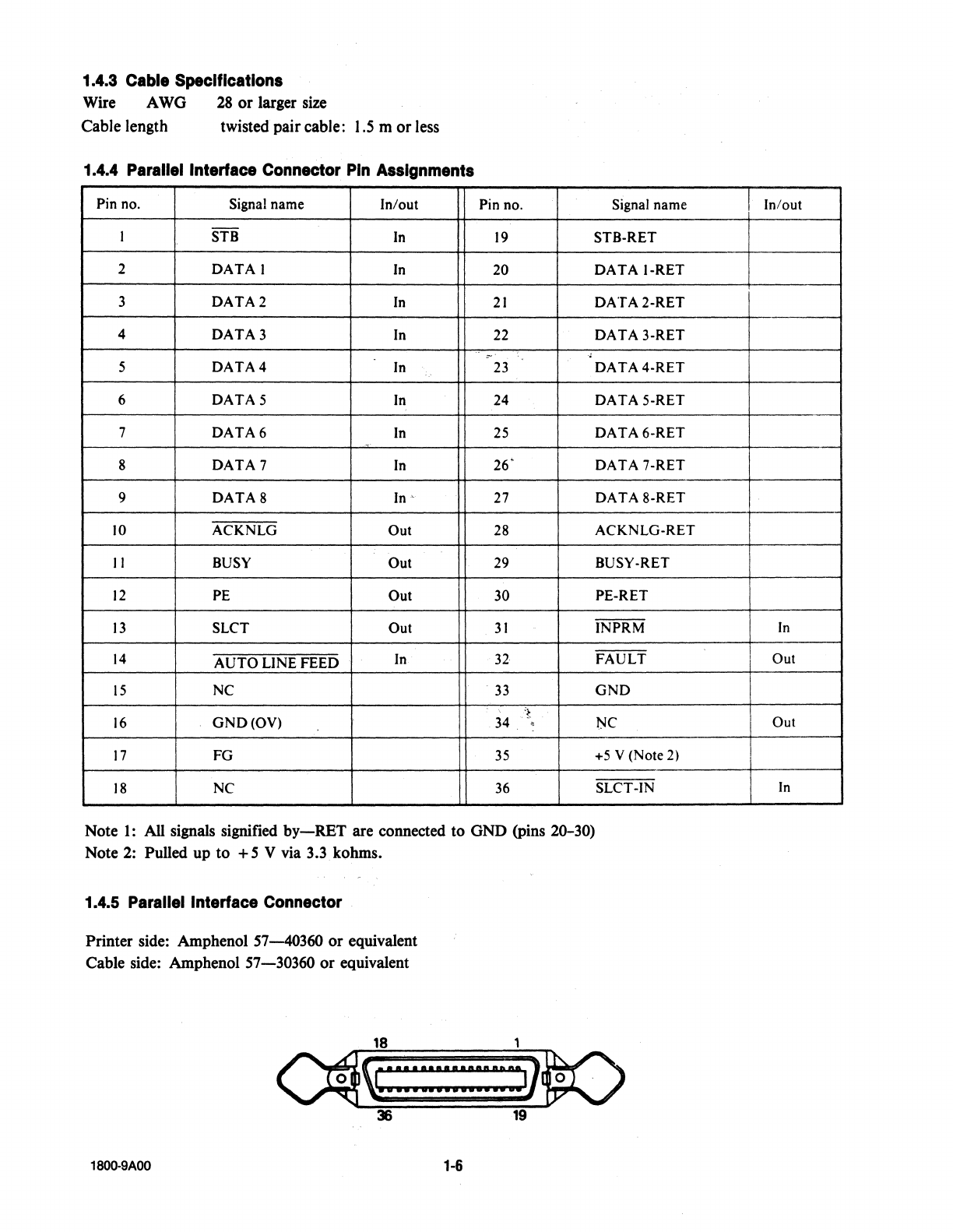
1.4.3
Cable
Specifications
Wire AWO
28
or larger size
Cable length twisted paircable:
1.5
m orless
1.4.4
Parallel
Interlace
Connector
Pin
Assignments
Pin no. Signal name In/out Pin no. Signal name
I STB
In
19
STB-RET
2
DATA!
In
20
3
DATA2
In
21
4
DATA3
In 22
.-
'
5
DATA4
In
23
6
DATA5
In 24
7
DATA6
In
25
8
DATA
7
In
26"
9
DATA8
In
27
JO
ACKNLG Out 28
11
BUSY
Out
29
12
PE Out 30
13
SLCT Out
31
14
AUTO
LINE FEED
In
32
15
NC 33
16
GND(OV)
34
~-
~
17
FG 35
18
NC 36
Note
1:
All signals signified
by-RET
are connected to GND (pins 20-30)
Note 2: Pulled up to +5 V via 3.3 kohms.
1.4.5
Parallel
Interface
Connector
Printer side: Amphenol
57-40360
or equivalent
Cable side: Amphenol
57-30360
or equivalent
18
~:
::
:
:::::::::::
::i]
36 19
1800-9AOO
1-6
DATA
1-RET
DATA2-RET
DATA
3-RET
DATA4-RET
DATA
5-RET
DATA
6-RET
DATA
7-RET
DATA
8-RET
ACKNLG-RET
BUSY-RET
PE-RET
INPRM
FAULT
GND
NC
+5
V (Note 2)
SLCT-IN
Jn/out
--
--
+
In
I
I
Out
Out
In

1.4.6 Description of Input Signals
(a)
DATA I - 8 O Bits 1 - 8
of
character code and image data
O Read into the printer strobed by STB.
O DATA I - 8 should not vary while STB =
L.
--
(b)
STB O Strobe signal to read DATA I - 8
O STB
is
effective when BUSY=
L.
O The next STB should not be output before ACKNLG appears.
(c)
INPRM o Signal to initialize the printer
O
If
INPRM appears when the priater
is
operating,
it
stops imme-
diately. Initialization
is
executed at the rise
of
INPRM from
"L"
to
"H".
~
0 INPRM I i
-t----1-
Sµs(min)
·~
--
(d)
ACKNLG 0 Acknowledge signal responding to STB
O
The
next STB should not be output before ACKNLG returns.
O ACKNLG
is
output independently
of
STB under the following
conditions.
a)
INPRM has appeared after power-on to put the unit
in
ON-
LINE mode.
b) OFF-LINE mode has changed to ON-LINE.
(e)
BUSY 0 When BUSY is H, the unit
is
busy.
0 When BUSY
is
L, the unit
is
ready. ACKNLG
is
output when
BUSY decays to L.
o BUSY is
Hin
OFF-LINE mode.
<0
PE 0 PE rises to H when paper runs out.
• Except when the paper sensor switch
of
the SO-characters/line
printer
is
set to
CUT
SHEET,
or
when the paper release lever
of
the 156-characters/line printer
is
set to a position other than
PIN FEED.
(g)
SLCT o When SLCT
is
H, the unit
is
selected.
(h) FAULT O FAULT
is
Lin
the following conditions.
a)
When paper
is
out.
b) In off-line mode
(i)
AUTO
LINE FEED 0 When AUTO LINE FEED
is
L, one linefeed
is
executed
following execution
of
CR.
(j)
SLCT-IN O When SLCT-IN is L, the unit
is
selected.
1800-9AOO
1-7

1.4.7 Timing Diagram (Parallel Interface)
Tt
T2
T3
DATA
STi
_Jf1-t
--
BUSY
ACKNLG
:=:-_:::::::-_r=--=---=-~~
Tl
T2
T3
T4
0.5
0.5
0.5
4.0
µs(min)
µs (min)
µs(min)
µs(min)
~4uS
Note:
The
timing
of
CD
can be selected with
jumper
J5
of
the
80-characters/line printer
or
J3
of
the
156-characters/line printer. When the machine leaves the factory, the timing is set
to@.
1.4.8 Optional Interface
Serial interface (RS-232C
or
current loop) can be incorporated by installingan option card.
1800-9AOO
1-8

2.1
GENERAL
SECTION 2
THEORY
OF
OPERATION
This sectioncontains block diagrams, timing diagrams, flow charts, electroniccircuits
and
descriptions
of
the func-
tions
of
this printer. Differences between the 80-column
and
156-column units are included.
180Q.9AOO
2-1

PowerON
f--
Reset
* 4MHz
6MHz 2.2
CONTROL
CARD
BLOCK
DIAGRAM
MPU
6802/68A02
HBO
$0800 -
$1
FFF
H136
$3800-$5FFF
OataBUS
ADR
BUS
$0090
-
$0093
! Shift
I
P.ulse
~
',,
,~.,__
__
---'
------v
•'
PIA
I
Feed
Pulse
D B
ff
6B21/
ata
u er
68
A
21
1----l~
80
characters/line
6Kt-9---+-+--+--__.
611 3 x 3
Panel
~
56 characters/line 1
OK
,..
'
SW
___
_.
(RAM)
.,.__--+'.___.....__,.
6116+6264
$00CO -$00C3
$COOO
-
$FFFF
PROG&
CG
ROM
12K
HBO
$2000-
$3FFF
H136
$AOOO
-$BFFF
r---~-----------
I NLQCG NLQCG
I
• Option
ROM
'
•
ROM
I
I
(RAM)
'
r--i 8 K
------·-
SK
f--,
PPl-2
Dip.SW
8255A
$00AO -
$00A3
1
1
Dip.
SW
PPl-1
~--~
ii
Print
~
$00E0,$00FO Signal
----V
8255A
L
__
-I
__
...
L--...1
$00FO NLQCG
Selectflip-flop I $00EO
$0098
-$009F
PTM
6840/68A40
*NOTE-4
MHz IS FOR
140
CPS UNIT;
6 MHz IS FOR
160
CPS
UNIT.
1800-9AOO
-
Address
Decoder
2-2
$0080
Hand
1"
Shake
Signal~---,/
Data
Latch
+24V: MotorPrint Head
+SV:
IC
LSI
GND:
t-
en
0
:I:

2.3 MEMORY MAP
HBO
H138
$0000
$0000
WORK&STACK
AREA
(Within
6802)
007F 007F Data Latch
0080 0080
0090 0090
1/0 ports (6821)
Data latch strobe
0093 0093 I
1-
0098 0098
...
1
---------
009F 009F
OOAO
OOAO
OOA3
OOA3
ooco
ooco
OOC3
OOC3
I
I
OOEO
OOEO
I
OOFF
I
OOFF
I
I
0800 3800 I
PTM
(6840)
PPI
1
(8255A)
PPI
2 (8255A)
CG
select
Data buffer
5-RAM
80
characters/line
HBO
6Kbytes
1
56
characters/line
1FFF
SFFF
H136
10Kbytes
2000
3FFF
cooo
FFFF
1800-9AOO
I
I
AOOO
~
1
-------~
NLQROM
SK bytes
BFFF
.____
______
_.
I
COOO
r
1
-------~
Program (firmware)
CG
ROM
(16K bytes)
FFFF
..._
_____
__.
l/O_Ports
~
D7
D6
D5
D4 D3 D2
D1
DO
Remarks
$0080(R)
DATA
DATA
DATA
DATA
DATA DATA
DATA DATA
8-b1t parallel
8 7 6 5 4 3 2 1 data in
ONLINE
ALARM
ONLINE
LF
FF
I\
PAPER
HOME
Control panel
$0090(R)
POSI-
LED LED
SWITCH
SWITCH
SWl1t:H
EMPTY
TION
inputs
$0092(W)
F~
Ft/13
Ft/12
Ft/11
s~
S4>3
Stb2
St/11
Stepping
motor
outputs
DIP
switch
SOOAO(R)
SW1.-8
SW1,7 SW1-6 SW1-5
' SW1-4 SW1-3 SW1-2
SW1-1
inputs
for
character set
$00A1
(W)
Ne
N1
No
Ns
N•
N•
N2
N1
Wire
dot
pin
outputs
~
\ Interface
signals
$00A2(W)
FAULT
SL~T
BUSY
ACKNLG
PE
N9
Auto-under-
line signal
DIP
switch
$00CD
(R)
SW2-8 SW2-7 SW2-6 SW2-5 SW2-4 SW2-3 SW2-2
SW2-1
for
setting
print
mode
$00CI
(R)
SW4-8
SW4-
7 SW4-6 SW4-5 SW4-4 SW4-3 SW4-2
SW4-1
Not
equipped
(R)
READ
mode
(W) WRITE mode
DIP
switch
for
setting
page
length
•
F,P1
-
4:
Paper feed
motor
pulse
S,P1
-
4:
Carriage
motor
pulse
6802 reset vector address table
Vector Contents
MS
LS
--
FFFF
FFFF
Restart (RES)
FFFC
FFFD
NMI
FFFA FFFB SWI
--
FFF8 FFF9 IRQ
2-3

2.4 INITIALIZATION ROUTINE
Initialize
timers
1-3
1800-9AOO
Turn on power
switch
Inhibitinterrupt
(IRQ)
Set stack pointer
Initialize
MPU registers
Initialize
6821 (PIAI
Initialize
6840(PTMI
Initialize
8255
A (PPl-1, PPl-2)
Initialize 1/0 port
Check
RAM
Initialize
motor
phases
Carriage
motor
Paper feed
motor
Setcarriage
home position
Feed
paperforward
and reverse
No
A
Reid initial values
of
the
DIP
switch
(Printer modesetting. etc.I
Yes
ALARM lamp lights.
Buzzer sounds.
Energize
200
µs
pulses
to
dot.64
times.
2-4
SWITCHES@
POWER ON
LF:ON
FF:OFF
LF:OFF
FF:ON
LF:ON
FF:ON
LF:OFF
FF:OFF
Teat modeprint
NLQ
printmode
isaet.
Hex dumplist
ONLINE
Ready
to
acceptdata

2.5 CONTROL CARD CIRCUITS
l. Power-on-reset circuit
2.
MPU
(68A02)
3.
ROM, RAM
4.
PTM
(68A40)
5.
PIA (68A21)
6.
PPI-l (8255A)
7.
PPI-2 (8255A)
8.
Head driver
9. Power supply
The printer incorporates a
68A02
8-bit microprocessor (MPU). A clock signal
of
1MHz
is
generated from 6 MHz
generated by a quartz crystal, to time data transfer operations.
The
printer consists
of
ROM which stores software, data buffer RAM, printer unit, control panel, buzzer and
LSis (PIA, PTM, PPI) which control interface ports. Each device is controlled by the timing signal output
fromMPU.
2.5.1
Power-On-Reset Circuit
The power-on-reset circuit initializes the MPU and resets the head to the home position.
Power-on-reset initializes the MPU, PIA,
PTM,
and PPI on one hand, and prevents the printer from printing
something
at
the moment
of
power-on on the otherhand.
At the moment
of
power-on, waveforms are as shown in Figure
2-1.
02
©
5V
©
ov
1800-9AOO
J-<"'"""lr-f"
~----~-------CL
L.....::;~:>--
CL
Reset MPU
20ms
• Head initialize
•
PPI
reset
R
13
PSTB
ZSCIZl:S
Figure
2-1
Power-On-Reset
Circuit
2-5
9
Head
driver
circuit
Nl"'-'N9

2.5.2
Microprocessor
Unit
(MPU)
The 68A02 MPU generates the basic clock
of
1 MHz
(1
uS) from a 6 MHz quartz oscillator.
The basic clock signal (E)
is
used to time data transfer operations between the MPU and peripheral LSis.
1800-9AOO
Vee
E
IOIM
r;:t1.RES
RES
_....__,,-oav
ti.RES
..
'7·
VMA-----
E
R/W
Address
From MPU
VMA
E
Address
From MPU
VMA
DATA
FromMPU
Figure
2-2
Re~et
Timing
530ns
max.
Figure
2-3
Read
Operation
Sequence
-------tcrc
1µ1
max.
Invalid da.ta
area
2.4V
0.4V
450ns
225ns ma11.
toow
2.4V
0.4V Doto Valid
Figure
2-4
Write
Operation
Sequence
2-6
This manual suits for next models
1
Table of contents
Popular Cables And Connectors manuals by other brands

ODU
ODU MEDI-SNAP Assembly instructions

Extron electronics
Extron electronics Two Conductor MHR - Mini High Resolution S-Video Cable MHR-2... Specification sheet

hager
hager 4 RJ 45 User instructions

National Instruments
National Instruments NI-XNET LIN operating instructions

Sennheiser
Sennheiser ASP 1 Instructions for use

Davis Instruments
Davis Instruments Crimp-Type Splice Connector install guide


