CENTURION SYSTEMS RDO II User manual

- 1 -

- 2 - INSTALLATION MANUAL – RDO
IMPORTANT SAFETY RECOMMENDATIONS
FAILURE TO COMPLY WITH THE FOLLOWING SAFETY RECOMMENDATIONS MAY
RESULT IN SERIOUS PERSONAL INJURY, DEATH AND/OR PROPERTY DAMAGE.
1. READ AND FOLLOW ALL SAFETY AND INSTALLATION INSTRUCTIONS
CAREFULLY.
2. The installation of your new Automatic Garage Door Opener (hereinafter referred to as
“RDO II”) must be carried out by a technically qualified or licensed person. Attempting to
install your new RDO II without suitable technical qualification may result in severe
personal injury, death and/or property damage.
3. Only install the RDO II on a properly-balanced and aligned, well-functioning garage door. An
improperly-balanced or malfunctioning garage door could cause serious injury. Have a qualified
person check, and if required, make repairs to your garage door before installing the RDO II. As
a general rule, your garage door is deemed to be well-balanced and aligned if it;
a. Requires an equivalent amount of applied force to manually open or close and,
b. Requires no more than 150N of applied force to either manually open or close and,
c. Does not rise or fall more than 100mm when stopped at any position between fully open or
fully closed positions and,
d. Does not rub on or make contact with any supporting or surrounding structures.
4. Repairs to garage doors must only be carried out by technically qualified persons. Attempting to
repair the garage door without suitable technical qualification may result in severe personal
injury, death and/or property damage.
5. Remove or render inoperative all existing locks and ropes prior to installation of the RDO II.
6. The counterbalance springs on sectional type doors must be properly lubricated between all of
the coils with heavy automotive bearing grease. Failure to adequately lubricate the springs may
result in one or more of the following symptoms;
a. The springs will become rusty over time resulting in extra operating friction between the
coils which may cause the RDO II to malfunction.
b. Seasonal temperature changes may cause the garage door springs to expand and/or contract.
The resultant increase and/or decrease in operating friction may cause the RDO II to
malfunction. Properly lubricating the springs will help to minimise the effect of seasonal
temperature changes in operating friction of your garage door.
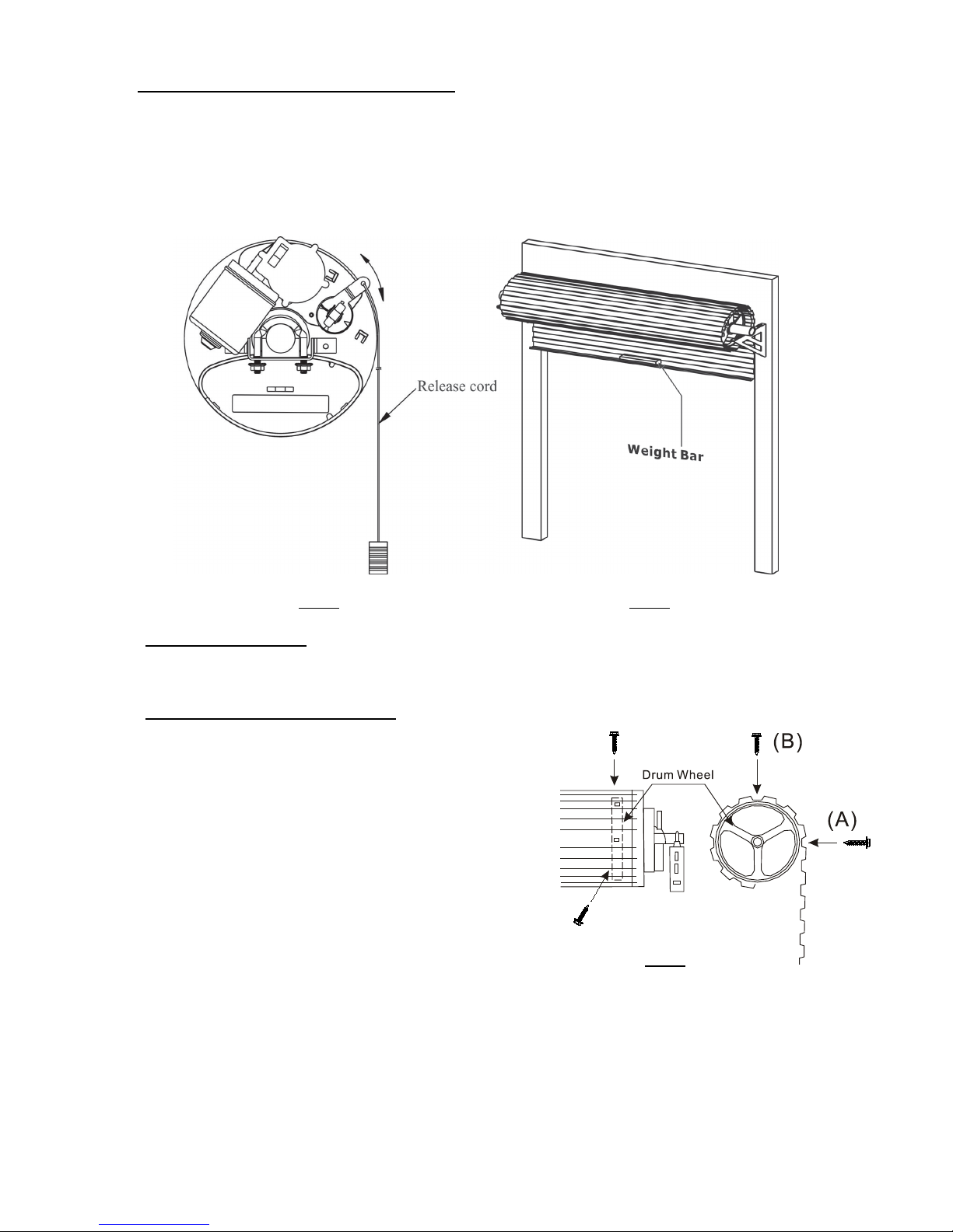
7. If possible, install the RDO II at least 2 meters or more above the ground. Adjust the Manual
Release Cord so that it hangs approximately 1.8 meters from the ground.
8. Do not connect the RDO II to the power source until this manual instructs you to do so.
9. The RDO II must be connected to a properly-earthed general purpose 220V outlet which has
been installed by a qualified electrical contractor.
10. If one remote is to be used as a wall pendant, locate it;
a. Within site of the garage door and,
b. At a minimum height of 1.5 meters above the ground so that it remains out of the reach of
small children and,
c. Away from all moving parts of the door.
11. Install the Entrapment Warning Label in a prominent position next to the wall-mounted remote
control.
12. The Manual Release Instruction Tag must remain attached to the Manual Release Cord.
13. After installing and correctly adjusting the RDO II, the garage door must stop and reverse
direction when it comes into contact with a 35mm high solid object placed on the floor under the
garage door.

- 3 - INSTALLATION MANUAL – RDO
14. The correct function of the Safety Obstruction Reversing System should be checked on a
monthly basis. Make sure that the garage door reverses when it makes contact with an
obstruction.
15. Never use the RDO II unless the garage door is in full view and free from objects such as cars,
children and/or adults.
16. Never allow children to operate the RDO II.
17. Never operate the RDO when children/persons are under or near the path of the door. Children
must be supervised at all times when near the garage door and when the RDO II is in use.
18. Never attempt to disengage the RDO to manual operation when there are children/persons and/or
other objects including motor vehicles under or near the path of the garage door.
19. Never attempt to open or close the garage door by pulling on the Manual Release Cord.
20. Never attempt to make any repairs or remove covers from the RDO II without first disconnecting
the power supply cord from main power supply.
21. For additional safety, we strongly recommend the fitment of Safety Beams. Although the RDO II
incorporates a pressure sensitive safety obstruction system, the addition of Safety Beams will
greatly enhance the operating safety of the Automatic Garage Door and provide additional peace
of mind. In some countries, it is a mandate of law to fit Safety Beams. It is the sole responsibility
of the owner/installer to fit Safety Beams in those countries which so require.
22. Removal of the RDO II’s protective covers must only be performed by a technically qualified
person. Attempting to remove the protective covers or repair the RDO II without suitable
technical qualification may result in severe personal injury, death and/or property damage.
23. Always ensure that the garage door is fully open before driving into or out of the garage.
24. Always ensure the garage door is fully closed before leaving the driveway.
25. Adjustments to the Safety Obstruction Force settings must only be carried out by a technically
qualified person. Attempting to adjust the Safety Reverse Force setting without suitable technical
qualification may result in severe personal injury, death and/or property damage.
26. Keep hands and loose clothing clear of the garage door and product at all times.
27. In order for the Safety Obstruction Force System to function it must first encounter an
object/person on to which some force MUST be exerted. As a result the object/person/door may
suffer DAMAGE OR INJURY.
28. The Safety Obstruction Force System is designed to work on STATIONARY objects only. If
the garage door encounters a moving object during an Open or Close Cycle, serious
personal injury, death and/or property damage may occur.

- 4 - INSTALLATION MANUAL – RDO
24 Month carry-in product warranty
Note: You can register your product(s) online at www.centsys.com, which will assist you in keeping a record
of your date of purchase or installation, serial numbers, etc.
All of our products are manufactured with extreme care, thoroughly inspected and tested.
The goods supplied by us shall be subject to the provisions of sections 55 to 57 of the Consumer Protection Act
(68/2008) except where the provisions of the warranty contained in our product documentation are more favourable
to the purchaser. Subject to the warranty contained in our product documentation, if applicable, our products are
warranted for a period of twenty-four months after delivery. However, it is expressly noted that batteries carry a six
month warranty due to the nature of these products being such that they are subject to possible misuse. Please note
that warranties will be honoured on a carry-in basis; in other words, the product in question must be taken in to one
of our branches, or to the authorised reseller that the product was purchased from, for assessment and, if necessary,
repair. For equipment not of our manufacture, the warranty as supplied by the original manufacturer will apply if
such warranty is more favourable to the purchaser than the relevant provisions of the Consumer Protection Act (Act
68/2008 of South Africa), or any other applicable law as so required in different countries in which the product was
sold. Such warranty is valid only once full payment has been received for such goods.
Australian customers:
Our goods come with guarantees that cannot be excluded under the Australian Consumer Law. You are entitled to a
replacement or refund for a major failure and compensation for any other reasonably foreseeable loss or damage.
You are also entitled to have the goods repaired or replaced if the goods fail to be of acceptable quality and the
failure does not amount to a major failure
Any warranty may be voidable on any equipment which:
1. Has not been installed in accordance with the installation instructions provided.
2. Has been subject to misuse or which has been used for any purpose other than that designed for by the
manufacturers.
3. Has damage caused as a result of handling during transit, atmospheric conditions (including lightning), corrosion
of metal parts, insect infestation, power surges or other forces outside of the control of the manufacturer.
4. Has been repaired by any workshop and / or person NOT previously authorised by the manufacturer.
5. Has been repaired with components not previously tested, passed or authorised by Centurion Systems (Pty) Ltd,
South Africa or one of its subsidiary companies.
Any warranty may be voidable on any equipment if:
1. There has been a failure to install the product in accordance with the installation instructions provided by the
manufacturer, or a failure to abide by the safety instructions provided by the manufacturer, or
2. There is no breach of a legal duty of care owed to you by us or by any of our employees or agents.
3. Such loss or damage is not a reasonably foreseeable result of any such breach, and any increase in loss or
damage resulting from breach by you of any term of this contract.

- 5 - INSTALLATION MANUAL – RDO
Fig 1
Fig 2 Fig 2A
Fig 3 Fig 3A

- 6 -
REQUIREMENTS PRIOR TO INSTALLATION
A. Forward
Your RDO II is comprised of two major individual components, namely the
Drive Unit (top figure alongside) and Control Box (bottom figure alongside).
This section of the manual deals with the basic fitting requirements which should
be met before you attempt to install your opener. Study them carefully to ensure
that your door and surroundings are suitable for such an installation.
Important Note: The procedures outlined in this manual require a certain degree of
technical and mechanical skill. It is not recommended that your RDO II be installed
by a home handyman. The RDO II should always be installed, serviced and
adjusted by a technically qualified person.
B. Side Room Requirement
The recommended minimum and maximum door mounting bracket position as measured
from the edge of the garage door curtain is depicted in Fig.4. The ideal distance should
be between 85~125mm as indicated.
Important Notes:
•The fixing distance may vary from garage door to garage door
depending on the distance that the garage door drum wheel has
been set inside the garage door curtain
•If the door drum wheel has been set too deep inside the garage
door curtain, it is recommended to fit an additional drum
wheel closer to the edge of the curtain facilitating easier
installation of the RDO II unit. This product is available from
Centurion Systems (Pty) Ltd
•The installer should verify the correct distance by actually
checking the measurement prior to mounting or moving any
garage door brackets
Fig 4
C. RDO II to garage door compatibility
If, for whatever reason, the plastic forks of the RDO II do not fit into or align with the slots in the garage door
drum, or you wish to reinforce a structurally unsound drum, a special adaptor plate can be purchased from
Centurion Systems (Pty) Ltd. Instructions for the installation of the adaptor plate are included with the product.
Examples of garage door drums that would require the use of the RDO adaptor plate:
Example 1 Example 2 Example 3 Adaptor plate
Fig. 5

- 7 - INSTALLATION MANUAL – RDO
D. Check For Correct Function Of The Door
Before beginning the installation of the RDO II, check that the garage door is functioning correctly. The garage
door must be well-balanced and operate smoothly and freely. When opened to between 900~1200mm from the
floor and released, the garage door should remain in one fixed position and not rise or fall more than 100mm. It
should not bind or stick in the side tracks. The ideal operational effort required to open or close the garage door
should not exceed a force of 15kg. (Refer Item 3, Page 2)
Important Note: The RDO II must not be installed on a poorly-adjusted, worn or damaged door.
E. Weight Bar
The main purpose of the weight bar is to eliminate the possibility of the garage door curtain “ballooning” when
starting from the fully open position. With the weight bar fitted, the garage door should have a natural tendency
to lightly free fall from the mid-open position.
F. Left / Right-Hand Installation
The RDO II has been factory-set to be installed on the right-hand end of your garage door (when viewed from
inside the garage looking out). Flip dipswitch 6 to the ‘ON’ position for a left-hand installation, and to the ‘OFF’
position for a right-hand installation. Please refer to Section 13.4 for further information.
G. Control Box Location
Mount the Control Box on a smooth, flat surface. The area must be completely free from
exposure to water, either direct (rain, garden hose, sprinklers, etc.) or indirect
(seepage either through or down the internal face of the wall). The Control Box contains
sensitive electronics which will sustain damage as a result of any water ingress.
Water-damaged electronics are not covered under the terms of the opener warranty.
Important Note: The control box is not waterproof!
H. Battery Charger
The plug-in battery charger is provided to keep the batteries charged to an optimum voltage. A green coloured
LED, located on the charger casing will illuminate to indicate that the charger has been connected to an active
power supply.
Important Note: Do not mount the charger any further away from the control box than the connection
cable allows. Please ensure that a 220V mains point is provided at the control box for the charger.
I. Battery Cable Connection
In order to conserve battery power prior to installation, the RDO II is
supplied with the positive (red) battery cable disconnected from the
battery terminal.
Connect this cable as follows prior to commencing the installation;
Remove the Control Box lid and connect the red cable to the positive
(+) battery terminal as depicted in Figure 6 (Item 7).
Once connected, the lid can be refitted.
Fig. 6

- 8 - INSTALLATION MANUAL – RDO
INSTALLATION INSTRUCTIONS
1. Mounting The Control Box
1.1 Establish a location at approximately chest height on the same wall face as that of the Door Mounting to which
the Drive Unit will be secured. Make sure that the cable running from the Control Box is long enough to reach up
to the Drive Unit for the location that has been selected.
1.2 Use the Mounting Template provided on Page 22 of this manual, mark the location of the three Control Box
mounting screws.
1.3 Drill a 6mm hole at each of the three marked locations to an approximate depth of 75mm.
1.4 Insert a wall plug (provided) into each of the three holes.
1.5 Insert a self-tapping screw (provided) into each of the green plugs and leave the heads exposed from the wall
(protruding approximately 6mm).
1.6 Locate the three recessed mounting slots on the center back of the Control Box base plate and “hook” the Control
Box onto the screws.Note: The mounting screws may need to be adjusted for depth if the Control Box will not
hook onto the screws or if the Control Box does hook on but is loose.
1.7 At this stage, DO NOT plug the Charger into a power socket.
2. Fitting Of Drive Unit to The Door (Right-Hand Installation Depicted)
2.1 Check that the door U-bolt is securely tightened on the opposite end of the door to which the Drive Unit will be
fitted (Fig.7)
2.2 Open the door fully and ensure that the bottom stoppers of the garage door are engaged with the stoppers on the
door guide tracks.
2.3 Place a suitable prop under the door as close to the edge (to which the drive unit is being fitted) as possible. The
prop should be adjusted so that it sits firmly under the door. (Fig.8)
2.4 Important Note: The door curtain can become damaged quite easily once the full weight of the door is
imparted on the prop. The prop must be strong enough to sustain the full weight of the door but at the
same time have enough padding that it will not damage the door curtain. The suitability of the prop should
be determined by a technically qualified person. No claims for door damage will be recognised under the
terms of the RDO II’s guarantee when using an unsuitable prop.
Fig 7Fig 8

- 9 - INSTALLATION MANUAL – RDO
2.5 Remove the U-bolt from the end of the garage door to which the Drive Unit will be fitted.
2.6 Having ensured that the prop is stable and firmly in position, remove the garage door mounting bracket from the
wall.
2.7 If not already disengaged, disengage the RDO II Drive Unit by pulling once on the release lever (Fig.11) - the
forked drive gear should now rotate freely
2.8 Orientate the Drive Unit as per Fig.9
2.9 Slide the centre of the Drive Unit over the garage door axle. Push the Drive Unit fully into the garage door and
ensure that one of the garage door drum wheel spokes slides in between the forks of the Drive Unit.
2.10 Refit the garage door mounting bracket to the wall. The U-Bolt slots in the door bracket must align with the
U-bolt mounting slots in the Drive Unit. (Fig.10)
2.11 Important Note: In some cases the door mounting bracket may need to be repositioned in order for the
U-Bolt holes align.
2.12 Fully insert the specially supplied U-bolt through the Drive Unit and garage door mounting bracket slots.
2.13 Affix and firmly tighten the U-Bolt with the two securing nuts provided.
2.14 Check the manual operation of the door by fully raising and lowering the door. The door should run smoothly
and should not catch on any part of the Drive Unit assembly.
Fig 9
Fig 10
3. Adjusting Release Cord
3.1 Unfurl the Red Disengage Cord and cut it to an appropriate length so that its end hangs approximately 1800mm
above the garage floor.

- 10 - INSTALLATION MANUAL – RDO
4. Engaging and Disengaging The Drive Unit
4.1 To disengage the Drive Unit from the garage door pull down on the Red Release Cord. (Fig.11)
4.2 To engage the Drive Unit to the garage door pull down once more on the Red Release Cord.
4.3 Important Note: Always disengage the Drive Unit with the garage door in the fully closed position.
4.4 Important Note: If attempting to disengage the Drive Unit from any position other than with the garage
door fully closed, ensure that there are no persons and/or property near or directly under the path of the
garage door.
Fig 11 Fig 12
5. Fitting of Weight Bar
5.1 Fit the weight bar to the top edge of the garage door bottom rail as depicted in Fig.12
6. Fixing of Curtain to Drum Wheel
6.1 The garage door curtain must be secured to the drum wheel with suitable
fasteners such as self-drilling screws or rivets.
6.2 With the garage door in the fully closed position, mark the
curtain at points “A” and “B” as depicted in Fig.13
6.3 Once marked, open the door slightly so as to have access to the
marked positions. Secure the curtain to the drum wheel ensuring
that the fixing points are at least 90 degrees apart.
Fig 13

- 11 - INSTALLATION MANUAL – RDO
SETTINGS AND ADJUSTMENTS
Fig 14 Fig 15
7. Door Travel Adjustment – Open Direction
7.1 With the Drive Unit in disengaged mode, move the door up by hand to the fully open position.
7.2 Remove the limit cover to expose the Limit Adjust Cams (Opening and closing limit cams - Fig.14 and 15).
7.3 Slightly loosen the three cam locking screws (to the extent that you can rotate the cam by hand with a firm push)
7.4 Rotate the Open Limit (Lower) Cam (Item 2 Fig.15) by hand, in the direction of the Open Limit (Lower) Switch,
until you hear the switch “click”. Once the Open Limit Switch “clicks”, continue to rotate the cam a further 10
degrees or so towards the switch.
7.5 To check the Open Limit Switch adjustment - Move the door down by hand and then slowly back up again. The
limit switch should “click” approximately 100mm BEFORE the door stops making contact with the rail stops.
7.6 If not, then adjust the Open Limit Cam accordingly.
8. Door Travel Adjustment – Close Direction
8.1 With the Drive Unit in disengaged mode, move the door down by hand to the fully closed position.
8.2 Move the door down by hand to the desired fully closed position.
8.3 Rotate the Close Limit (Upper) Cam (Item 5, Fig 15) by hand, in the direction of the Close Limit (Upper) Switch,
until you hear the switch “click”. Once the Open Limit Switch “clicks”, continue to rotate the Cam a further 10
degrees or so towards the switch.
8.4 To check the Close Limit Switch adjustment, raise the door by hand and then slowly lower again. The Close
Limit Switch should “click” approximately 100mm BEFORE the door touches the ground. If not, adjust the
Close Limit Cam accordingly.
9. Connecting to Power Supply
9.1 Connect the RDO Battery Charger to a properly-earthed power supply.
9.2 Switch the power on at the power supply – the LED on the charger should glow green.
Important Note: Do not mount the charger any further away from the control box than the connection cable
allows.
10. Door Travel - Final Adjustment
10.1 Open the garage door to the midway position and then pull once on the red disengage cord to engage the RDO
to the garage door
10.2 Test the garage door open and close positions by pressing the red “operate” pushbutton located on the front face
of the Control Box.
10.3 Check that the garage door opens and closes to the required positions. If not, re-adjust the Open and/or Close
Limit Cams accordingly.
10.4 Turn the appropriate cam TOWARDS the Limit Switch to DECREASE garage door travel and AWAY from the
appropriate Limit Switch to INCREASE garage door travel.
10.5 Once finally adjusted, firmly tighten the three Limit Cam Locking Screws and refit the Limit Cover Plate.

- 12 - INSTALLATION MANUAL – RDO
11. Safety Obstruction Force Adjustment
Dual Safety Obstruction Force Adjustment modes ensure that the RDO can be optimised to suit virtually any garage
door
•
Adaptive Mode – constantly monitors incremental drive force value changes that occur due to seasonal conditions
and / or garage door aging. Adaptive Mode compensates for these variables by automatically adjusting Safety
Obstruction Force values during every complete cycle, resulting in enhanced safety and minimised chances of
garage door ghosting1.
•Manual Mode – features conventional one time Safety Obstruction Force value
adjustment and is more suited for use on badly-worn or improperly-balanced garage
doors. (Refer Section 11.2. for setup details)
11.1. Adaptive (A) Mode
Enabling
•If Adaptive Mode is already enabled then skip to the next section titled “Functionality”
•To enable Adaptive Mode carry out the following procedure;
•Switch off power at power supply
•Remove the Courtesy Lamp and Control Box Covers to expose the Control Board
•Select Dipswitch No.1 to the “ON” position
•Replace the Control Box and Lamp Covers
•Switch power on at power supply
Fig. 16
Functionality
•In order to learn the required run time and drive force values, the RDO II will be required to complete five
(manually activated) uninterrupted open and close cycles (commencing from the Close Limit Point)
•During the course of the cycles, the LIGHT will quick flash once every two seconds and the operating parameters
will be learned in the following order;
•Open Stroke 1 – Alignment stroke
•Close Stroke 1 – Learn run time between Open Limit Point and Close Limit Point
(during Close Cycle 1 the RDO II will not Slow Stop)
•Open Stroke 2 – Learn run time between Close Limit Point and Open Limit Point
(during Open Cycle 1 the RDO II will not Slow Stop)
•Close Stroke 2 – Learn Drive Force Values between Open Limit Point and Close Limit Point
•Open Stroke 3 – Learn Drive Force Values between Close Limit Point and Open Limit Point
•Once Learning has been successfully completed, the LED Indicator will commence to slow flash
Important note: During initial power-up learning, the Safety Obstruction Force values of the RDO II default to
a maximum setting. Encountering a solid obstruction during the course of the initial learning cycles may result
in garage door damage. It is recommended that initial learning cycles be carefully supervised in order to prevent
the possibility of the garage door hitting an obstruction causing personal and/or property damage.
Safety Obstruction Force Adjustment
•Open the Courtesy Lamp Cover to expose the adjustment controls
•Rotate the (green) “Offset” Adjustment Pin in a clockwise direction to increase Safety Obstruction Offset Value
and in an anti-clockwise direction to decrease the value
•The Safety Obstruction Offset Value may be adjusted within a range of 30N (3kg) to 100N (10kg)
•The selected value remains identical for both open and close direction travel
•Refer to ‘Testing Safety Obstruction Force’ for testing
1. Ghosting is defined as a Safety Stop or Safety Reverse without the garage door actually encountering an obstruction.

- 13 - INSTALLATION MANUAL – RDO
Forced learn
•A Forced Learn may be initiated by holding down the “Learn” Button for three seconds – LED Indicator will
begin to quick flash
•Cycle the RDO II through five complete uninterrupted strokes (commencing from the close limit point) in order
for it to complete the learning process. The LED Indicator will cease to quick flash once learning has been
completed
Important Note: During a Forced Learn, the Safety Obstruction Force values default to a maximum setting.
Encountering a solid obstruction during the course of the initial learning cycles may result in garage door and /
or property damage. It is recommended that the learning cycles be carefully supervised during this time.
Automatic Re-Learn
•A re-learn of Drive Force and Run Time parameters will be automatically initiated immediately subsequent to
either one of the following occurrences;
•
Run Time deviation becoming excessive
•
Safety Reversing on three consecutive occasions
•
Safety Stopping on three consecutive occasions
•During this period the LED Indicator will quick flash
11.2. Manual (M) Mode
Enabling
•If Adaptive Mode is your desired selection, then refer back to Section.11.1. to
enable Manual Mode;
•
switch off power at power supply
•
remove the Courtesy Lamp and Control Box Covers to expose the Control
Board
•
select Dipswitch No.1 to the “OFF” position
•
replace the Control Box and Lamp Covers
•
switch power on at power supply Fig. 17
Entering Safety Obstruction Force Adjustment mode
•Hinge open the Courtesy Lamp Cover to expose the adjustment controls.
•Press and hold down the “Learn” Button (Figure.17) for two seconds - LED Indicator will commence a paused
double flash.
•Safety Obstruction Force Adjustment can be carried out while LED Indicator is “paused double flashing”
•To close out Safety Obstruction Force Adjustment Mode momentarily press “Learn” Button
Note: Mode will close out automatically after 10 minutes if not closed out manually beforehand.
Safety Obstruction Force Adjustment – Open Direction
•Hinge open the Lamp Cover to expose the adjustment controls
•With the garage door in the fully closed position, press the black “Run” Button (Figure.17) so that the garage door
begins movement in the open direction
•While the garage door is opening slowly, turn the (green) Open / Offset Adjustment Pin (Figure.17) in an
anti-clockwise direction until the garage door stops
•Now turn the same pin clockwise five degrees
•Refer to ‘Testing Safety Obstruction Force’ for testing
Safety Obstruction Force Adjustment – Close direction
•With the garage door in the fully open position, press the black “Run” Button (Figure.17) so that the garage door
begins to close
•While the garage door is closing, slowly turn the (red) Close / Speed Adjustment Pin (Figure.17) in an
anti-clockwise direction until the garage door stops and begins to Safety Reverse
•Now turn the same pin clockwise five degrees
•Refer to ‘Testing Safety Obstruction Force’ for testing

- 14 - INSTALLATION MANUAL – RDO
Testing Safety Obstruction Force
Open direction
•With the garage door in the fully closed position, stand inside the garage just behind the path of the garage door
close to its middle position
•Press the black “Run” Button (Figure.17) so that the garage door begins to open
•When the garage door has opened by approximately 450mm apply some firm downward force to one of its
structural members
•If the Safety Obstruction Force Adjustment is correct the RDO II will stop the garage door upon sensing the
applied force
•If too little or too much force is required to make the RDO II stop, rotate the (green) Open / Offset Adjustment Pin
five degrees in the appropriate direction (clockwise to increase force, anti-clockwise to decrease force) and then
repeat the previous testing steps
Close direction
•With the garage door in the fully open position stand inside the garage just behind the path of the garage door
close to its middle position
•Ensure that the Close Limit Travel Adjustment (Section.8) has been set so that the bottom of the garage door is
resting firmly against the ground
•Press the black “Run” Button so that the garage door begins to close
•Place a 32mm thick block of wood under the line of the garage door (approximately at the midpoint of the garage
door) so that the garage door will close onto the block of wood.
•If the Safety Obstruction Force Adjustment is correct, the RDO II will stop and reverse the direction of the garage
door upon sensing the block of wood
•If the RDO II stops but does not reverse then turn the (red) Close / Speed Adjustment Pin five degrees in an
anti-clockwise direction.
Fig. 18

- 15 - INSTALLATION MANUAL – RDO
12. Remote controls
The RDO II offers four menu levels pertaining to four different functions that can be activated via the two
four-button NOVA code-hopping remote controls supplied with this kit. Depending on individual
preference, one remote can be kept in the user’s car, while the other remote is mounted against the wall
and used as a pendant, or the extra remote can simply be kept as backup. The hole in the body clip can be
used as a mounting slot to affix one remote against the wall and use it as a remote Wall Pendant. . It can be
mounted in a convenient location such as adjacent to a side entry door into the garage. The buttons can be used for
activating the various functions provided by the system
Mounting
1. Rotate the inner casing of the remote and remove it from the outer (body) clip.
2. Mark the position of the unit against the mounting surface.
3. Using a 5mm masonry bit, drill a single hole into the mounting surface.
4. Mount the outer clip against the wall using appropriate fasteners and rawl plugs (obtainable from a hardware
store)
5. Replace the inner casing in the outer clip.
Important note: The wall-mounted remote must be mounted within sight of the garage door and a reasonable
distance away from moving parts. It should be mounted at least 1500mm above the ground and the Entrapment
Warning Label provided, must be attached adjacent to the remote.
Each menu level and function has a different effect upon the controller and the load which it controls.
To enter Learn Mode, momentarily press the Learn button. The number of flashes on the LIGHT and LED will indicate
the level of the menu the controller is currently in. The operator will stay in Learn Mode for 10 seconds after the last
button press of a remote control or wall pendant being learned into the system. The LIGHT will quick flash for 2
seconds indicating the controller is exiting Learn mode. A button will have to be pressed and held for at least three
seconds in order to be learned into the controller’s memory.
Important notice: It is of the utmost importance that the Forced Learn procedure which calibrates the operator
to suit the opening and closing requirements of the door, has been completed BEFORE attempting to learn
remotes or wall pendants. Forced Learn is initiated by pressing and holding the Learn button for two seconds,
after which the LED will begin to rapidly flash to indicate that the unit is in Learn mode. After invoking the
Forced Learn procedure, the user can start to open and close the unit as per the standard limit learning
procedure.
12.1. Function One – Open/Close
This function is associated with opening and closing the door only.
Operation
Momentarily press the associated transmitter button to open, stop or close the door. If the door is busy closing, pressing
the transmitter button will cause the door to immediately reverse its direction of travel and start opening. If, on the
other hand, the door is busy opening, pressing the transmitter button will cause the door to stop. Pressing the
transmitter button a second time will cause the door to reverse its direction of travel and start closing.
Learning procedure
Press the Learn button ONCE. The LIGHT and LED indicator will now flash once every two seconds, indicating that
Function One Learn has been selected. Take the remote control or wall pendant that must be learned into the system,
press and hold the desired button for three seconds. The LIGHT and LED will flash three times if the transmitter has
been successfully learned The LIGHT will flash three times to confirm that the button has been successfully learned
into Function one. Proceed this way to learn any other transmitter in the system to operate Function One only. The
system will remain in this learn mode for 10 seconds after the last remote or wall pendant is learned and automatically
exit after this time. The function can be learned to any button, provided that the button has not yet been learned to
another function.
12.2. Function Two – Light

- 16 - INSTALLATION MANUAL – RDO
Learning a button to Function Two will enable that button to switch the Courtesy Light on and off.
Operation
Momentarily press the associated transmitter button to either switch the courtesy light on or off. If the light has been
switched on, it will time out as per the maximum current timer of 2 minutes.
Learning procedure
Press the Learn button TWICE to select Function Two Learn, if the operator is still in Learn Mode, the Learn button
need only be pressed once. The LED indicator will flash twice every two seconds to confirm that Function Two Learn
has been selected. Take the remote control or wall pendant that must be learned into the system, press and hold the
desired button for three seconds. The LIGHT and LED will flash three times if the transmitter has been successfully
learned into Function Two and will activate the courtesy light upon being pressed. The system will remain in this learn
mode for 10 seconds after the last remote or wall pendant is learned and automatically exit after this time. The function
can be learned to any button, provided that the button has not yet been learned to another function.

- 17 - INSTALLATION MANUAL – RDO
12.3. Function Three – Holiday Lockout
Learning a button to Function Three will enable that button to electronically lock the controller for use. In other words,
no transmitters or inputs will be able to trigger the operator.
Operation
To engage Holiday Lockout Mode, the button learned to engage this function must be pressed for three seconds before
Holiday Lockout Mode will engage. The courtesy light will emit a single flash. When disengaging Holiday Lockout
Mode, a double flash indicate likewise. When the door reaches the closed position, the courtesy light will remain in the
ON state and time out as per normal. Should a button which operates Function One other than any of those associated
with Holiday Lockout Mode be pressed whilst the operator is locked, the LIGHT will flash twice to indicate the
operator is locked. The associated transmitter/wall pendant button must be pressed for three seconds before the Holiday
Lockout Mode will engage/disengage. If the door is in the closed position, the lock will engage immediately. However,
if the door is in the open or partially open position, the door will first close before engaging Holiday Lockout.
Learning procedure
Press the Learn button THREE times to select Function Three Learn. If the operator is still in Learn Mode, the Learn
button need only be pressed once. The LIGHT and LED will flash three times every two seconds to indicate that
Function Three learn has been selected. Take the remote control or wall pendant that must be learned into the system
and press and hold the desired button for three seconds. The LIGHT and LED will flash three times to confirm that the
button has been successfully learned into Function Three, allowing activation of Holiday Lockout Mode as described
below. The system will remain in this learn mode for 10 seconds after the last remote or wall pendant is learned and
automatically exit after this time. The function can be learned to any button, provided that the button has not yet been
learned to another function.
12.4. Function Four – Autoclose Override
This function will allow the associated button to override the Autoclose function if it has been selected, resulting in the
door staying open.
Operation
The operation of this function is described as follows:
12.4.1. With the door in the closed position, the Autoclose Override button must be pressed and held for at least
three seconds to engage/activate this function
12.4.2. The light will flash quickly a number of times and simultaneously the buzzer will emit multiple beeps to
confirm the operation of this function
12.4.3. The door will also operate to open and stay open without Autoclosing
12.4.4. Pressing the open/close button will trigger the door to close
Learning procedure
Press the Learn button FOUR times to select Function Four Learn. If the operator is still in Learn Mode, the Learn
button need only be pressed once. The LIGHT and LED indicator will flash four times every two seconds, indicating
that Function Four learn has been selected. To learn a button to this function, press and hold the desired button for three
seconds. The LIGHT will flash three times to confirm that the button has been successfully learned into Function four.
The system will remain in this learn mode for 10 seconds after the last remote or wall pendant is learned and
automatically exit after this time. The button can be learned to any function, provided that the button has not yet been
learned to another function.
12.5. Delete Remotes
All remote control codes may be deleted as follows:
12.5.1. Hinge open the Courtesy Lamp Cover to expose the ‘Learn’ Button
12.5.2. Momentarily press the ‘Learn’ Button - LED Indicator will flash slowly
12.5.3. Press and hold the black ‘Run’ Button - LED indicator will begin to rapid flash.
12.5.4. All remote control codes will have been deleted once the LED indicator ceases to flash
12.5.5. Close the Courtesy Lamp Cover

- 18 - INSTALLATION MANUAL – RDO
13. Options and Features
13.1. Accessory connections
•Four Output Terminals are provided to support the connection of the most common external accessories
•The Output Terminals can be accessed by removing the Courtesy Lamp and Control Box Covers.
•Connection Diagrams
•CENTURION i5 or equivalent four-wire Safety Beams (Figure 19B)
•24V DC universal receiver (Figure 19C)
•RDO two-wire safety beam (Figure 19A)
•Wall switch – hardwired (Normally-open contact – Figure 19D)
Fig. 19
13.2. Autoclose
•Autoclose can enhance the security of your property by ensuring that your garage door is never unintentionally
left open
•Autoclose will automatically close the garage door;
•Three seconds after reaching the open limit point - provided that a person or object has passed through the
Safety Beams during the open cycle, or
•upon expiry of the pre-set 30 seconds delay time – provided that a person or car has not passed through the
Safety Beams within the delay time
Important note: Autoclose will only function when used in conjunction with Safety Beams.
Enabling
•Remove the Courtesy Lamp and Control Box Covers to expose the Control Board
•Select Dipswitch Nos.2 (SB) and 3 (AC) to the “ON” position (Figure.20)
•Replace the Control Box and Courtesy Lamp Covers once selection has been completed

- 19 - INSTALLATION MANUAL – RDO
13.3. Courtesy lamp
•The built-in Courtesy Lamp will switch on each time the RDO II is activated and then switch off automatically 90
seconds after receiving the last remote control or run signal.
•In order to conserve remaining battery power the Courtesy Light will not function once battery voltage falls below
24V
Bulb replacement
•Hinge open the Courtesy Lamp Cover to expose the bulb
•Remove the bulb by first pushing in and then turning anti clockwise
(same as removing and replacing a household light bulb)
•Replace bulb with identical 24V 21W Incandescent
•Close the Courtesy Lamp cover
Important note: Replacing the bulb with 12V version will cause the transformer to overheat and may
permanently damage the transformer and Control Board. Always ensure that replacement bulb is rated at 24V
and no more than 2W.
13.4. Dipswitches
•The Dipswitches located on the Control Board (Figure.20) enable or disable specific functionality
•The Dipswitches can be accessed by removing the Courtesy Lamp and Control Box Covers
(Refer Section.5.6 for removal and replacement details)
•Read through the following table and select the specific functionality best suited your specific personal or garage
door requirements.
Functionality table
Table 1
Function
Dip No
Position
Adaptive Mode (A/M)
1
ON
Manual Mode (A/M)
1
OFF
Safety Beams (SB)
2
ON
Safety Beams (SB)
2
OFF
Autoclose (AC)
3 & 2
ON
Autoclose (AC)
3
OFF
Door Service Monitor (DSM)
4
ON
Door Service Monitor (DSM)
4
OFF
For future functionality
5
ON
For future functionality
5
OFF
Left-Hand Installation
6
ON
Right-Hand Installation
6
OFF
For future functionality
7
ON
For future functionality
7
OFF

- 20 - INSTALLATION MANUAL – RDO
13.5. Learn Button
•The “Learn Button” (Figure. 17) is located within the Lamp Cover adjacent to the “Learn LED” and serves to
initiate the functions as described in Table 2:
Function
Action
Learn remote control code
Momentary press
Formal Force Learning
Press and hold for two seconds
Table 2
13.6. LED Display
•The LED Indicator (Figure.17) is located under the Courtesy Lamp Cover and serves visual indication of
functionality sequences as described in Table 3:
Display
Indicator
Glow Solid
Reached close limit position.
Slow Flash
Reached open limit position.
Medium Flash
Learning or deleting remote control codes
Quick Flash (A Mode)
Learning new drive force parameters
Quick Flash (M Mode)
Force adjust mode activated
Table 3
13.8. Run Button
•The black “Run” Button (Figure.17) is located under the Lamp cover and serves to initiate the functions as
described in Table 4:
Function
Action
Activate RDO II
Momentary press
Table 4
13.9. Safety Beams
•The CENTURION i5 or other four-wire Safety Beams may be connected to the RDO II (For two-wire beams, set
the jumper to 2W. For four-wire beams, set the jumper to 4W (Figure 19))
•The installation of Safety Beams greatly enhances safety by constantly monitoring for persons or objects which
may pass within the path of the moving garage door
•The RDO II will commence to Safety Reverse if the Safety Beams become momentarily or permanently
interrupted during a Close Cycle
Mounting
•Mark the inside garage door framing so that the bottom edge of the i5 beam sits 125mm off the floor
•Using a small angle bracket, fasten each beam to the wall so that they face each other across the garage door
Connection
•Follow Safety Beam instructions and connect to the Output Terminals. Use the normally-open contacts of the beam
to connect to input SB4 on the RDO (Figure 19A/B)
Important note: RDO II provides 24V DC output and normally-open input.
Alignment
•Adjust the Safety Beam module marked “Transmitter” (by turning the mounting bracket) so that it is aimed
directly at the lens of the Safety Beam module marked “Receiver”. A GREEN indicator lamp located on the
“Receiver” will glow once the correct alignment has been achieved
•Test the Safety Beam alignment several times, each time ensuring that when the Safety Beams are obstructed
the green indicator lamp extinguishes and when unobstructed the indicator lamp glows solid
•Firmly tighten the Safety Beam mounting bracket fixing screws
•Installation of the Safety Beams is now complete
Enabling
•Remove the Courtesy Lamp and Control Box Covers to expose the Control Board
•Select Dip 2 (SB) to the “ON” position (Figure.20)
•Replace the Control Box and Courtesy Lamp Cover
Table of contents
Popular Door Opening System manuals by other brands

Dorma
Dorma 8616 ARNP manual

DITEC
DITEC Entrematic Hurricane DS20 Installation and service manual

Sesamo
Sesamo PROSWING operating instructions

Assa Abloy
Assa Abloy Corbin Russwin PED5800 Series installation instructions

Dormakaba
Dormakaba 8900 IS installation instructions

hager
hager 8300 Series quick start guide