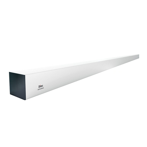
DITEC Entrematic Hurricane DS20 Manual

Installation and Service Manual
FBO
Slide Package
Ditec DS20H

Complies with applicable sections of NFPA 101 and the IBC Life Safety Codes for Manually Operated Pedestrian Doors.
Copyright 2020, Entrematic. All rights reserved. Reproduction in whole or in part without the express written permission of Entrematic
is prohibited.
.

CONTENTS
1
Revision ....................................................................................................................................................5
2
Instructions for safe operation .......................................................................................................... 6
3
Important information ....................................................................................................................... 8
3.1 Intended use....................................................................................................................................8
3.2 Safety precautions ...........................................................................................................................8
3.3 Electronic equipment reception interference...................................................................................8
3.4 Environmental requirements............................................................................................................8
3.5 Glazing materials.............................................................................................................................8
4
Technical specification ...................................................................................................................... 9
5
Design and function description ..................................................................................................... 10
5.1 Function.........................................................................................................................................10
5.2 Microprocessor for precise control ................................................................................................10
5.3 Emergency escape........................................................................................................................10
6
Models ....................................................................................................................................................11
7
Identification ...........................................................................................................................................12
7.1
Options ...................................................................................................................................13
8
Space required ............................................................................................................................... 15
9
Pre-Installation........................................................................................................................................16
9.1 General tips/Safety concerns .........................................................................................................16
10
Mechanical Installation ................................................................................................................... 17
10.1
Checking.................................................................................................................................17
10.2 Installation Overview .....................................................................................................................19
10.3 Installation Examples.....................................................................................................................20
10.4 Site Inspection...............................................................................................................................22
10.5 Installation and Adjustment Processes .........................................................................................23
11
Electrical connections .................................................................................................................... 57
11.1 Installation .....................................................................................................................................57
11.2 Mains connection...........................................................................................................................58
11.3 Electrical units ...............................................................................................................................59
12
Break Out/Safety – Hold Beam Connection Diagram .................................................................... 64
13
Start-Up ..................................................................................................................................................65
13.1 Adjustments and selection of special operating functions .............................................................65
13.2 The Learn function can be one of three different types..................................................................67
13.3 Display test and configuring of parameters ...................................................................................68
13.4 Status indication on the display ....................................................................................................69
13.5 Description of parameters .............................................................................................................70
14
Signage ..................................................................................................................................................85
15
Accessories ............................................................................................................................................85
15.1 Interconnection cable....................................................................................................................85
15.2 Program selectors .........................................................................................................................87
15.3 Accessory board............................................................................................................................86
15.4 Program selector options ..............................................................................................................88
15.6
Electrical locks...............................................................................................................................90
15.7
Motion sensors ..............................................................................................................................90
15.8 Night mode .......................................................................................................................90
15.9
Bottom Guide Systems .................................................................................................................91
15.10
Open / Close function ....................................................................................................................91
15.11
Fire alarm connection....................................................................................................................91
15.12
Nurse function ...............................................................................................................................91
15.13
Remote Exit mode.........................................................................................................................91
15.14
Emergency open impulse..............................................................................................................91

16
Troubleshooting............................................................................................................................................ 92
16.1 Main control unit display................................................................................................................94
16.2 Mechanical checking and remedies ..............................................................................................94
16.3 Error description and remedies .....................................................................................................95
16.4 After remedy or replacement, the operator has to be checked as follows:....................................95
17
Service/Maintenance ..............................................................................................................................96
17.1 Service...........................................................................................................................................96
17.2 Planned Maintenance Checklist ....................................................................................................97
18
Door Handing & Layout.................................................................................................................. 98
18.1
Door Handing (Automatic Door Industry) .................................................................................98
19 ANSI/BHMA A156.10 (2017),.................................................................................................................99
19.1 Sliding Doors ..........................................................................................................................99

1 Revision
1021327-US-0.0
Issue 11/30/2020
5
1
Revision
Following pages have been revised:
Page
Revision


1021327-US-0.0
Issue 11/30/2020
7
2 Instructions for safe operation
2
Instructions for safe operation
•
Failure to observe the information in this manual may result
in personal injury or damage to equipment.
•
To reduce the risk of injury of persons - use this operator only
with pedestrian doors.
•
Do not use the equipment if repair or adjustment is
necessary.
•
Disconnect supply when cleaning or other maintenance is to
be carried out.
•
The operator can be used by children age 8 and above, and
persons with reduced physical, sensory or mental
capabilities, or lack of experience and knowledge, if they
have been given supervision or instruction by a person
responsible for their safety concerning safe operator use and
the possible hazards involved.
This does not however prevent those persons to use the door
where the operator is installed.
•
Cleaning and user maintenance shall not be made by
children without supervision.
•
Do not let children climb on or play with the door or the
fixed/re- mote controls.
•
Make sure that the wall is properly reinforced at the
installation points.
•
Make sure that the power is off before installing.
•
Ensure that the surface is even, particularly when attaching to
block or concrete surfaces - level and shim as necessary.
(Failure to provide and even surface results in warping the
profile making it impossible to snap the filler tube together.)
•
Use care that all holes are deburred to prevent electrical
shorts.
•
In all instances, where work is being done, the area is to be
secured from pedestrian traffic, and the power removed to
prevent injury.

3 Important information
8
Issue 11/30/2020
1021327-US-0.0
•
Installer must properly ground door package! Improper
grounding can lead to risk of personal injury.
•
The mains connection must remain isolated until the
wiring is completed. Then connect to the supply unit.
•
The door set can be operated automatically by sensors or
manually by activators.

1021327-US-0.0
Issue 11/30/2020
9
2 Instructions for safe operation
3
Important information
3.1
Intended use
The Ditec DS20 Hurricane is designed for an overhead-concealed installation between two
vertical jambs or surface applied. The header holds the drive and control units and supports
the sliding doors, Sidelites and transom above the operator, if required.
A Ditec DS20 Hurricane operator ensures all-around safety. It can be combined with the full
range of Entrematic safety units, such as presence and motion sensors.
It is easy to install for both new construction and retrofit applications and can be adapted to a
wide range of overhead concealed or surface applied installations.
For use see Owner’s Manual 1021328
3.2
Safety precautions
To avoid bodily injury, material damage and malfunction of the product, the instructions
contained in this manual must be strictly observed during installation, adjustment, repairs and
service etc.
Factory authorized training is required to carry out these tasks safely. Only Entrematic-trained
technicians should be allowed to carry out these operations.
3.3
Electronic equipment reception interference
The equipment complies with the European EMC directive (US market FCC Part 15),
provided installed according to Installation and Service manual.
The equipment may generate and use radio frequency energy and if not installed and used
properly, it may cause interference to radio, television reception or other radio frequency type
systems.
If other equipment does not fully comply with immunity requirements interference may occur.
There is no guarantee that interference will not occur in a particular installation. If this
equipment does cause interference to radio or television reception, which can be determined
by turning the equipment off and on, the user is encouraged to try to correct the interference
by one or more of the following measures:
•
Re-orient the receiving antenna.
•
Relocate the receiver with respect to the equipment.
•
Move the receiver away from the equipment.
•
Plug the receiver into a different outlet so that equipment and receiver are on different
branch circuits.
•
Check that protective earth (PE) is connected.
If necessary, the user should consult the dealer or an experienced electronics technician for
additional suggestions.
3.4
Environmental requirements
Entrematic products are equipped with electronics and may also be equipped with batteries
containing materials which are hazardous to the environment. Disconnect power before
removing electronics and battery and make sure it is disposed of properly according to local
regulations (how and where) as was done with the packaging material.
3.5
Glazing materials
The glazing material for sliding doors shall comply with ANSI Z97.1.


1021327-US-0.0
Issue 11/30/2020
9
4 Technical specification
4
Technical specification
Manufacturer:
Entrematic Inc.
Address:
1900 Airport Road, Monroe, NC 28110, US
Type:
Ditec DS20 Hurricane
Main power supply:
100 V AC -10% to 240 V AC +10%, 50/60 Hz, fuse 10 AT
(building installation)
Note:
The mains power supply shall be installed with protection
and an all-pole mains switch with isolating capability of Category
III, at least 1/8" (3 mm) between contacts, shall be installed
according to local regulations. These articles are not provided
with the door.
Power consumption:
Max. 250 W
Degree of protection:
IP20
Degree of protection,
control actuators:
IP54
Auxiliary voltage:
24 V DC, 1 A
Recommended max.
door weight:
Ditec DS20 Hurricane Bi-parting
104” H x 192” W:
400 lb./leaf (180 kg/leaf)
Bi-parting 128” H x 192” W:
440 lb./leaf (200 kg/leaf)
Single Slide 104” H x 108” W:
420 lb./leaf (190 kg)
Single Slide 128” H x 96” W
440 lb./leaf (200 kg/leaf)
Clear opening:
Bi-parting:
Ditec DS20 Hurricane-2: 37
1/2"
– 82
1/16"
(952 – 2084 mm)
Single Slide:
Ditec DS20 Hurricane-R/L: 29
1/2"
– 46
3/16"
(749 – 1173 mm)
Opening and
closing speed:
Variable up to approx. 4.5 ft/sec. (1.4m/s)
(Ditec DS20 Hurricane-2)
To be adjusted to comply with ANSI/BHMA A156.10. Note that
local codes may vary.
Hold open time:
0-60 s
To be adjusted to comply with ANSI/BHMA A156.10. Note that
local codes may vary.
Ambient temperature:
-4°F to 130°F (-20 °C to +55 °C)
Relative
humidity
(non-
condensing):
Max. 85%
The Ditec DS20 Hurricane complies with: ANSI/BHMA A156.10, UL 325, UL 60730,
NFPA 79
For indoor use only
Note:
The glazing material of all doors shall comply with the requirements in the American
National Standard Performance Specification and Methods of Test for Safety Glazing Material
Used in Buildings, Z97.1.

5 Design andfunction description
10
Issue 11/30/2020
1021327-US-0.0
5
Design and function description
Design
The sliding door operator Ditec DS20 Hurricane works electromechanically. The
motor, control unit, transmission and optional emergency unit and electromechanical
locking devices are all assembled in a support beam with an integrated cover. The
motor and gear box transmit movement to the door leaves by means of a tooth belt.
The door leaf is fitted to a door adapter/carriage wheel fitting and hangs on a sliding
track. The guiding at the bottom is carried out by means of floor guides (Full Break-
Out).
Safety functions integrated in the operator
To permit safe passage between closing doors, the doors immediately reverse to
the open position if an obstruction is detected, then resume their interrupted
movement at low speed to check whether the obstruction has disappeared. If an
obstruction is detected between opening doors and surrounding walls or interior
fittings, the doors immediately stop and then close after a time delay.
5.1
Function
Opening
When an OPENING IMPULSE is received by the control unit the motor starts and
transmits movement to the door leaves, which move to the open position.
Closing
The closing starts when no OPENING IMPULSE is received and the HOLD OPEN
TIME has run out.
5.2
Microprocessor for precise control
The microprocessor has a routine for self-monitoring, which detects any interference
or faulty signals in door operation. If an input signal does not correspond to the
preprogramming, the microprocessor automatically takes necessary actions to
ensure safe door operation.
5.3
Emergency escape
The Ditec DS20 Hurricane can be combined with an emergency unit that
automatically opens or closes the doors in the event of a power failure and can also
be interfaced with the building fire alarm fire alarm or smoke detector. Safety can be
further reinforced by incorporating a break-out fitting. This enables the doors and
sidelites to swing outwards in an emergency situation by applying a defined
pressure at the front edge.
Doors used for emergency escape in buildings such as hospitals and homes for
elderly people may not be locked or put in program selection OFF.

1021327-US-0.0
Issue 11/30/2020
11
6 Models
6
Models
Entrematic provides several layouts for the Ditec DS20 Hurricane sliding door system.
Operators can be bi-parting or single slide (left or right handed) and sidelites may be
installed hinged to Break-out in emergencies. (See illustrations of various layouts in the
"Installation Examples" section on page 19.)
All Ditec DS20 Hurricane systems are ready for installation when delivered. The sidelites
and active leaves must be prepared with enclosed hardware. Operators are supplied with
all assembly hardware, and jambs have preinstalled threaded insert. (Anchoring
fasteners not included.)
Before installing the Ditec DS20 Hurricane system, check to see that you have been
supplied the correct equipment and that, all necessary tools and hardware are at hand.
Also, check the installation site for any factors that might interfere with proper installation.
(See "Installation Examples" section on page 19.)

7 Identification
12
Issue 11/30/2020
1021327-US-0.0
7
Identification
No.
Description
P/N
No.
Description
P/N
1
Mains connection
L2-6213
9
DS20H Beam
L7-1010
2
Power supply unit (PSU 150)
L2-6211
10
Tooth belt
L2-6100
3
Drive unit
L2-6210
11
Tension wheel
L7-1005
4
Main control unit (MCU)
L2-6212
12
Jamb, Hurricane
L7-5001
5
Transmission bracket (high)
L7-1001
13
Hurricane Door Stop Assembly
L8-1001
6
Belt clamp
L7-1004
14
Hurricane Beam End Cap
L8-1004 (right)
L8-1005 (left)
7
Transmission bracket (low)
L7-1003
15
Cover, Hurricane
L8-1009
8
Tandem Carriage Assembly
L8-1000
16
Standard operation 3-pos mode
selector
L8-1002

1021327-US-0.0
Issue 11/30/2020
13
7 Identification
7.1
Options
7.1.1
Active Leaf Panic Break-Out System
No.
Description
P/N
No.
Description
P/N
1
Panic Swing Arm (PSA)
L8-1006
6
Straight Slot Guide
Snap-in Insert
L8-1009
2
Door Carrier
L8-1007
7
Threshold 4.5”
L8-1010
3
Anti-Sag Adjuster
L7-1033
8
Ball Catch Kit, Sidelite
Door Portion, Hurricane
L8-1011
4
Hurricane Pin Guide
Assembly
L8-1008
9
Ball Catch Receiver,
Carrier Portion
L7-1039
5
Hurricane Tee Block
L8-1003
10
Hurricane Carrier End
Cap Assembly
L8-1012

7 Identification
14
Issue 11/30/2020
1021327-US-0.0
Note: Pivot pin must be pushed up fully
prior to tightening second screw from top to
lock into place
7.1.2
Sidelites and Break-Out
Sidelite, Break-Out (FBO)

1021327-US-0.0
Issue 11/30/2020
15
8 Space required
8
Space required

9 Pre-Installation
16
Issue 11/30/2020
1021327-US-0.0
9
Pre-Installation
This section will help you to determine the right configuration and preparation for your doors. a
Is this a Concealed Package?
b
Is this installation a bi-parting or single-slide?
c
If a single slide, what is the handing, left or right? (See "Door Handing" section on page 87).
d Where will power and signal wires enter the operator housing? (Back, End cover.)
eVerify substrate material.
9.1
General tips/Safety concerns
In all instances, where work is being done, the area is to be secured from
pedestrian traffic and the power removed to prevent injury.
•It is recommended that two persons install this package. The impact door panels can weigh up
to 220 pounds prior glazing. Using approved glass cups to move and set the doors is highly
recommended for the safety of the installers and protection of the door panels. This will also
ease the installation process and decrease the overall installation time.
•
If there are sharp edges after drilling the cable outlets, chamfer the edges to avoid damage
to the cables.
•
For enhanced security and vandalism protection, always mount the operator access in the
interior of a building whenever possible.
•
Make sure the ambient temperature is in the range specified in section Technical
specification.
•
Make sure that the power is off before installing.
•
Make sure that the door leaf and the wall are properly reinforced at the installation points.
•
Unpack the operator and make sure that all parts are delivered in accordance with the
packing note and that the operator is in good mechanical condition.
•
Ensure proper material is being used for the door leaves and that there are no sharp edges.
Projecting parts shall not create any potential hazards.
•
Ensure that entrapment between the driven part and the surrounding fixed parts due to the
opening movement of the driven part is avoided. The following distances are considered
sufficient to avoid entrapments for the parts of the body identified;
-
for fingers, a distance greater than 1” (25 mm) or less than 5/16” (8 mm)
-
for heads, a distance greater than 7-7/8” (200 mm)
-
for feet, a distance greater than 2” (50 mm)
-
and for the whole body, a distance greater than 19-11/16” (500 mm)
•
Danger points shall be safe guarded up to a height of 98-7/16” (2.5 m) from the floor level.
•
The operator shall not be used with a doorset incorporating a wicket door.
It is not possible to replace an Entrematic operator component with a
component from a different brand.

1021327-US-0.0
Issue 11/30/2020
17
10 Mechanical Installation
10
Mechanical Installation
10.1
Checking
Make sure that the wall is properly reinforced at the installation points.
Check that the wall material has the necessary reinforcements and that the floor is level
and smooth.
The beam/wall used to fix the support beam must be flat and smooth. If necessary use
mounting spacers (up to ¼” thick) behind the support beam to keep it straight.
Adequacy of the existing structural concrete/masonry, wood and metal framing as a main
wind force resisting system capable of withstanding and transferring applied product loads is
the responsibility of the architect or engineer of record for the project.
All anchoring fasters for the beam, jambs and thresholds are provided by the installer and
must meet the minimum requirements for the given substrate material (see table).
Fastening
requirements
Substrate material
Anchor type
Min embed
Min edge
dist
Concrete (2.85 ksi Min)
1/4" Elco Ultracon
1 3/4"
2 1/2"
Hollow or Grout-Filled CMU (ASTM C90) 1/4" Elco Ultracon 1 1/4" 2 1/2"
2x Min. Southern Pine Wood (G=0.55) #14 Grade 5 Wood Screw
1-3/8" 1"
16 Gauge (0.060") Min. Steel Stud, 33ksi Yield
Min., Or 1/8" Alum. 6063-Ts Min.
1/4"-14 Hilti Kwik-Flex or
ITW Teks Self-Drilling
Screw
Full
1/2"
Note: Anchors are flathead at strike locations and round/pan/hex-washer elsewhere. See
product approval drawings and documentation for full anchoring diagrams and requirements.
Note critical head size requirements, shown below. Typical fasteners are 3/16” x 1-3/4” HWH
Elco Ultracon for concrete substrate, #10x2” PH GR 5 Sheetmetal screw for wood substrate.

10 Mechanical Installation
18
Issue 11/30/2020
1021327-US-0.0
10.1.1 Test Equipment
a Stopwatch
b
Force gauge (50 lb. force range)
c
Multimeter
10.1.2 Tools required
a Set of metric box and wrenches
b Spirit level(48”+)
c
Tape rule
d
Power drill and set of drill bits, Unibit, Hammer drill
e
Metric hex key set 8, 6, 5, 4, 3 mm and 2.5 mm
f
Screw driver Torx T20, T27
g
Flat blade screw driver (small/medium/large)
h
#2 Phillips screw driver
i
Center punch
j
Wire stripper
k
Plumb bob
l Silicone sealant
m Pencil
n 18” drill bit extension
Additional mounting hardware not supplied – (see fastening requirements above)
Table of contents
Other DITEC Door Opening System manuals

DITEC
DITEC 0DT848 User guide

DITEC
DITEC DAS200 User manual

DITEC
DITEC NRG100TXE User manual

DITEC
DITEC Entrematic ENERGY 49E User guide

DITEC
DITEC COM E User manual

DITEC
DITEC 94 System manual

DITEC
DITEC DAB305 User manual

DITEC
DITEC DAS200T User manual

DITEC
DITEC DAS200TRF User manual

DITEC
DITEC Sprint User manual

DITEC
DITEC DAS200T User manual

DITEC
DITEC DOD Series Instruction Manual

DITEC
DITEC Sprint Manual

DITEC
DITEC BIS O Manual

DITEC
DITEC VALOR HH-HS User manual

DITEC
DITEC PASP User manual

DITEC
DITEC ENTREMATIC HA9 User manual

DITEC
DITEC DAS900FM User manual

DITEC
DITEC DAS107PLUS User manual

DITEC
DITEC VALOR User manual