CENTURION SYSTEMS WIZO-LINK User manual

WIZO-LINK
USER MANUAL
WIRELESS INPUT/OUTPUT MODULES
Centurion Systems (Pty) Ltd
www.centsys.com

After-sales
multi-language
Technical Support
Monday to Friday
from 07h00 to 18h00
GMT+2
Saturdays
08h00 to 16h30 GMT +2
Manufactures to
international
quality standard
ISO 9001:2008
100%
testing of
products
In-house
R&D
development
team
Centurion Systems (Pty) Ltd reserves the right to make changes to the products described in this
manual without notice and without obligation to notify any persons of any such revisions or changes.
Additionally, Centurion Systems (Pty) Ltd makes no representations or warranties with respect to
this manual. No part of this document may be copied, stored in a retrieval system or transmitted in any
form or by any means electronic, mechanical, optical or photographic, without the express prior written
consent of Centurion Systems (Pty) Ltd.
1986 1990 1995 1999 Today
Sales and technical support
to Africa, Europe, Asia,
the Americas, Australia

page 3
www.centsys.com
1. INTRODUCTION
1.1.1. Architecture
1.1.2. Security and Management Features
2. NETWORK REDUNDANCY
2.4.1. Establishing the Network
2.4.2. Network Transmission Integrity
2.6. Power Redundancy Options and Requirements
3. DISTRIBUTED I/O
3.1. What are inputs and outputs?
3.2.1. Modes of Operation
3.2.2. I/O Relationships
4. QUICK START SECTION
4.1. Getting Started
4.2. The WiZo User Interface
4.2.1. Power LED
4.2.2. NET LEDs
4.2.3. I/O
4.3. Default State
4.4. Master reset the WiZo (Factory Reset)
4.5.1. Network Master Process
4.5.2. Adding Additional Devices or Device Federation
PAGE 5
Page 5
Page 5
Page 5
Page 6
PAGE 7
Page 7
Page 7
Page 8
Page 8
Page 8
Page 10
Page 11
Page 12
PAGE 12
Page 12
Page 13
Page 13
Page 14
PAGE 16
Page 16
Page 16
Page 16
Page 17
Page 17
Page 19
Page 19
Page 19
Page 20
Page 20
Contents

page 4
www.centsys.com
4.6.1. One to One
4.6.2. One to Many
4.6.3. Implementing Further I / O Links
4.6.4. Output State
4.6.5. Modes of Operation for the WiZo Output
4.6.6. Removing an IO Link
4.6.7. Removing a Device from a Network
4.7. Supervision Mode
4.7.1. SupervisionModeNotication
4.7.2. Removing I/O Links while in Supervision mode
5. SPECIFICATIONS
6. INSTALLATION
6.1. Prepare for Installation
6.2. Potential Applications
6.3. Troubleshooting
6.3.1. Weak Signal
6.3.2. I/O
7. WARRANTY INFORMATION
8. APPENDIX
8.1. Wiring a G-ULTRA into a D-Series Controller via a WiZo
8.2. Wiring a G-ULTRA into a Electric Fence Controller via WiZos
8.3. Wiring a G-ULTRA into an Alarm System via WiZos
Page 21
Page 21
Page 22
Page 23
Page 24
Page 24
Page 25
Page 26
Page 26
Page 26
Page 27
PAGE 28
Page 28
PAGE 29
Page 29
Page 29
Page 30
Page 30
Page 30
PAGE 31
PAGE 32
Page 32
Page 33
Page 34
CONTENTS
Icons used in this manual
This icon indicates tips and other information that could be useful during the
installation.
This icon denotes variations and other aspects that should be considered during
installation.
note of critical aspects that MUST be adhered to in order to prevent
injury.

page 5 www.centsys.com
INTRODUCTIONSECTION 1
1. Introduction
is a mesh networkable product which enables a fully redundant network of
devices to be constructed. The network topology requires a minimum of two
devices to be connected to create a network; as more devices are added
network redundancy is improved until full redundancy is achieved. Integrated inputs and
outputs (I/O) enhance the Network’s ability to respond to events and actuate devices.
A network is a standalone network of devices that inter-communicate,
managing the distributed I/O. Each device is supervised, which ensures that, when a
deviceislosttothenetwork,anoticationissentsothatthenetworkcanbemaintained
to mitigate the loss.
1.1.1. Architecture
1.1.2. Security and Management Features
is comprised of two
elements:
1. The network, which enables
communication between
devices as both a receiver and a
transmitter.
2. The distributed I/O of which each
device has one input
and one output.
When a factory fresh device is powered up, it does not yet belong to a
network of devices. The device can either be added to an existing network or
beusedasaninitiatortocreateanewnetwork.Oncecongured,a device
retainsitscongurationevenwhenpowerislosttothedevice.
The network is initiated on a WiZo; which requires that one WiZo be elected as the
temporary mesh network master. As soon as a second WiZo joins the network, there is
no longer a need for the master role and it falls away, with the WiZo devices determining
the best message transmission route. As additional WiZo devices are added, the network
management is delegated amongst the WiZos, building up the mesh until it reaches full
network redundancy.
When a mesh network has been initiated and then federated, the devices
belong to a secure network with 128 BIT encryption. Additional nodes can only be added
to the network if one of the devices on the network is placed into “Add Node” mode.
This requires physical access to at least one device.
FIGURE 1. NETWORK ARCHITECTURE
RADIO FREQUENCY 2.4GHZ
INPUTS AND OUTPUTS
Owing to the federated nature of the network, when one device
is placed into “Add Node” mode, this places the mesh network of
devices into “Add Node” mode.

page 6
www.centsys.com
address. This means that, if by coincidence another WiZo is being
Once WiZo devices has been purchased, the user may be evaluating the installation
from one of two angles. Firstly, as an existing CENTURION customer who already has an
existing CENTURION product, or products, in operation, or secondly as someone new to
CENTURION’s product range wanting to get the most value for money out of his or her
purchases.
If you are an existing CENTURION customer, the enables you to enhance
your existing product investment. Each device adds distributed I/O which
can be used for several applications. Since the devices form a Mesh-able
Network, each new device improves the network strength. This is implemented with no
need for further infrastructure investment. Provided the device has power, and is able to
connect to the mesh network, it functions as an interconnected device enhancing network
capabilities.
If the user is a new CENTURION product customer, please keep in mind that WiZo-
isastandaloneproductoeringthatcananddoesintegratewithCENTURION’s
product range. forms a standalone network of devices, which has the option
of integrating via the G-ULTRA GSM unit and the G-REMOTE mobile application to be
activated and used as an interface to the network. This is, however, not a
requirement, and the network,oncecongured,willself-manageand
self-heal, functioning independently and reliably.
The WiZo network is a standalone network, which may consist of up to 50 or more
individual units. The network is constructed of devices, which are nodes on
the network. Once a device is added or allowed entry, the device is trusted
and is managed as a node on the network.
As a node, the improves the strength of the network by;
1. Adding an additional path or hop to the network.
2. network redundancy is improved.
3. additional I/O is added.
A single WiZo device does not form and cannot form a mesh network; a
minimum of two devices is required.
INTRODUCTIONSECTION 1

page 7 www.centsys.com
NETWORK REDUNDANCYSECTION 2
Full network redundancy takes full advantage of the mesh network integrity by ensuring
that the message that needs to travel will reach its destination. Redundancy can be
achieved with three devices or more. The device will continue to deliver the
mostrecentmessage,indenitely,untilthemessageisdelivered.Whenthemessage
is delivered, an acknowledgement is returned; all messages sent have end to end
acknowledgements.
In a mesh network, each device is connected to every other device in the network. In
an ideal environment, transmission is always perfect, and the message always arrives
intact.However,inpractice,manyfactorsinuencesignaltransmissionandthemesh
network principles and topology ensure that the message will always be delivered to its
destination. This is achieved by;
1. Line-of-sight or a direct connection,
2. through routing via adjacent devices.
The network strength or health is indicated locally at each device.
As shown in Figure 2, node A has
a direct line-of-sight connection to
node C. Node A can also route its
message via node B or node D to
reach node C.
The message has three routes
through which it can travel, which
guarantees that the message is
received, unless there is total
network failure.
Partial redundancy is achieved when
a node has at least one alternative
path to deliver its message to the
target device.
As shown in Figure 3, A has a line of
sight to node C. If the line of sight
is interrupted, the message will be
redirected via the mesh network via
node B.
FIGURE 2. FULL NETWORK REDUNDANCY
FIGURE 3. PARTIAL NETWORK REDUNDANCY
C
C
D
C
D
C
A
A
B
B
MESSAGE
MESSAGE

page 8 www.centsys.com
Although two devices are
required to form a basic network,
this does not constitute a mesh
network. Node A has direct line-
of-sight to Node B and Node B the
same for Node A; if there were
interruption, there is no alternative
path for the message to be
delivered.
When planning the network, a few essential elements must be considered before
physically installing each device or node. Since the is a wireless
device, physical installation is minimal, and this does allow for moving elements around.
However, sensible planning to begin with will ensure that the network is set up and
installed with minimal errors or issues.
When planning the network, it is important to consider the paths that are
available for a message to travel from one point to another. It is possible to create a
network where there is a combination of full- and partial-redundancy. When travelling,
the message may have line-of-sight from source to destination node, or the message
may be routed via multiple nodes before it reaches its destination. The
devices determine the best route to deliver the message, and good network planning
goes hand-in-hand with this process to ensure that the devices have enough available
paths to ensure that the message is delivered.
FIGURE 4. BASE NETWORK - NO REDUNDANCY
A
B
MESSAGE
NETWORK REDUNDANCYSECTION 2
devicesthatdonothaveanyI/Olinksconguredaddvaluetothe
network as they function as repeaters. This helps strengthen the robustness of
the mesh network.
When mastering the network, mastering onsite has the advantage of the master
selecting a channel that has low energy and minimal interference from other RF
devices or even an adjacent network.
Redundancyisaectedbythedistancebetweennodesaswellastheavailability
of nodes. This can be impacted by obstructions, where although the devices
are close enough, or there are enough nodes on the network, the interference
prevents the signal from being transmitted or received.
More than one WiZo Network can coexist on the same channel, provided they
are not in permit mode at the same time, which will interfere with federation.

page 9 www.centsys.com
NETWORK REDUNDANCYSECTION 2
Shown in Figure 5 below is an example network, which links several common devices
into a mesh network. Owing to proximity, certain devices have more than one path to
transmit and receive messages, whereas other devices do not. It is not always possible
to install the in an ideal location to guarantee optimal signal strength;
therefore, it is important to plan carefully to ensure that, as the installer, the devices are
not installed in such a way as to reduce signal strength, but so that signal strength is at
its best.
FIGURE 5. EXAMPLE NETWORK
Driveway
Geyser
JoJo Tank Out Building
Gate
Motor
House
Geyser
Garage Door
Geyser
Signal too
weak
WiZo added to improve
mesh capability
and ensure network
remains robust
Signal too
weak
Gate
Repeater
WiZo
Geyser
Borehole
Pump
When the mesh network is fully redundant two green LEDs will
illuminate in the NET area on the PCB. If only one is illuminated, this means
that the user does not have full network redundancy.
‘Lost’ refers to any number of eventualities which includes: device(s) struck by
lightning, power loss, etc., and does not necessarily refer to device failure.
The above example consists of the following:
A home which has the following devices near,
• Geyser
• JoJo Tank
• Borehole Pump
• Outbuilding Geyser
Devices which are further away from the home are,
• Garage Door
• Gate Motor

page 10
www.centsys.com
NETWORK REDUNDANCYSECTION 2
If, for example, the Garage Door WiZo was lost there would be no link between the
devices installed in the actual home and the gate motor as there was only one path
between the fully-redundant network and the adjacent nodes.
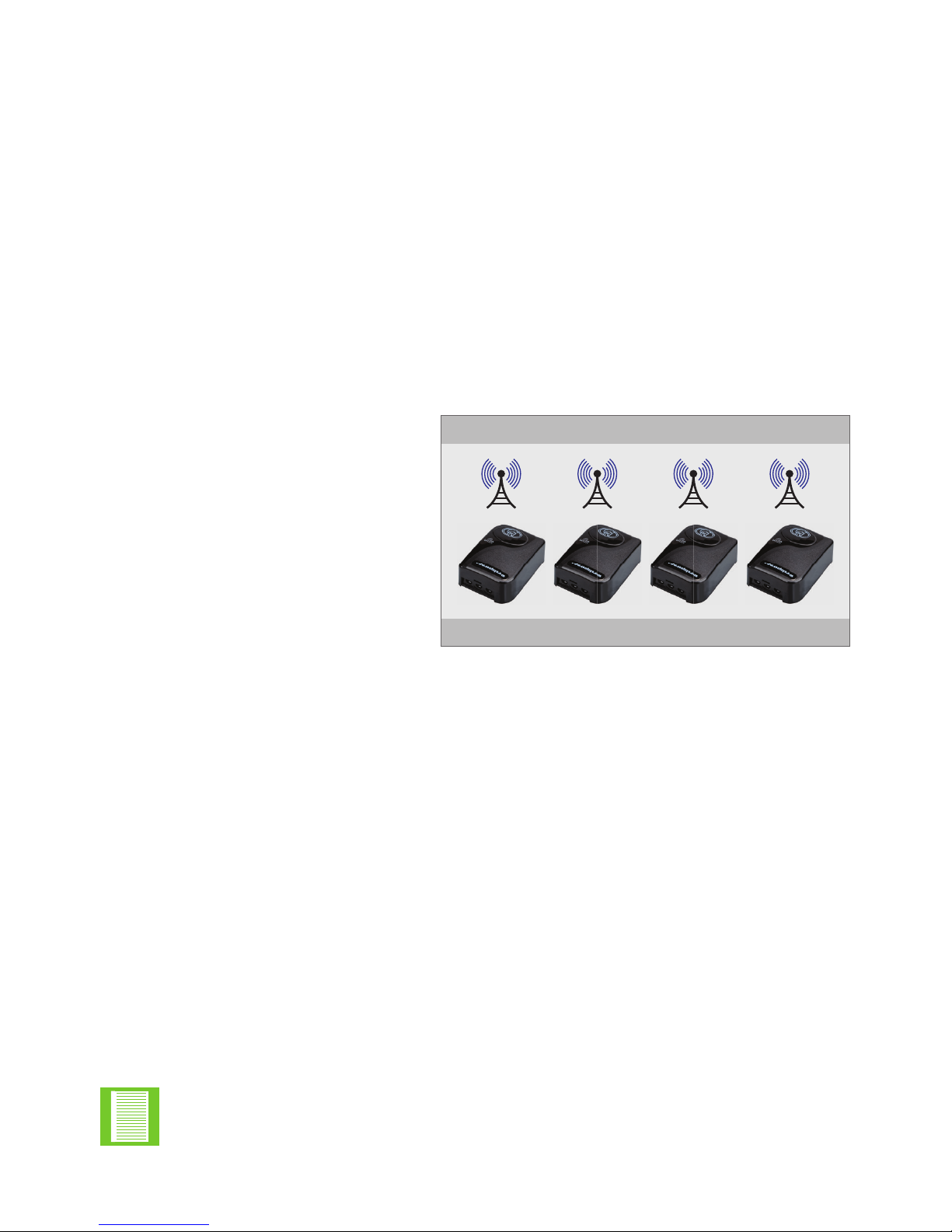
The devices located in the area around the home have higher redundancy, and they will
continue to function as a mesh network. To create a bridge or additional path to avoid
meshed failure, a can be installed and used as a repeater. Since each WiZo-
already functions as this in its usual role, once joined to the network this role is
fullledwithnoadditionalsetuprequired.
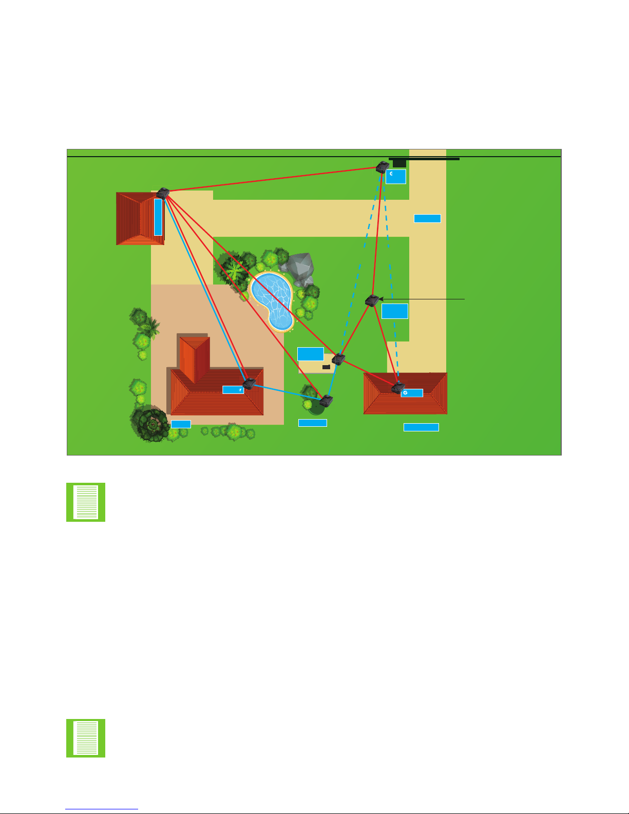
• If one notes in Area A, these devices all have full redundancy as there are
multiple paths available to deliver the message
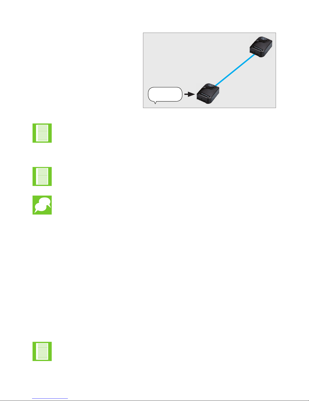
• However, in Area B, i.e. the distance between the Gate Motor and the Home
there is only one line-of-sight link. Message delivery is guaranteed provided there is
clearline-of-sightandthereissucientsignalstrength
We recommend that the not be installed in the following locations:
• Metal enclosures, which dampen signal
• Metal includes ferrous and non-ferrous
• Steel, mild steel, etc.
• Aluminium
• The device should not be installed on a metal base or other materials that can absorb
or dampen signal, and should be at least 100mm (See above)
• In area C, we do have partial redundancy; however, the number of paths for adjacent
nodes is limited
• In area D, a WiZo has been used as a repeater. This increases network strength by
adding in the additional path ensuring that network redundancy has been achieved
If the red LED illuminates in the NET section, the WiZo has lost signal and, if
the Amber LED illuminates, there is weak signal.
• When referring to transmission, we refer to the ability of the device to
transmit and receive signals via its antenna
• Atmosphericconditionscanaectwirelesstransmission.Thisincludesair
pressure, ambient temperature, lighting storms, dust storms causing static,
dry static ambient air and so on
The unit has an omnidirectional antenna on the PCB. This antenna has
a small surface area and, since it operates within the RF band, this means that it is
susceptible to interference. When installed, a few precautions must be observed to
ensure minimal interference exists.
The unit has an omnidirectional antenna on the PCB. This antenna has
a small surface area and, since it operates within the RF band, this means that it is
susceptible to interference. When installed, a few precautions must be observed to
ensure minimal interference exists.

page 11
www.centsys.com
• Nearoradjacenttodeviceswhichgeneratestrongelectromagneticelds,fore.g.
transformers, electric equipment, etc
• Line-of-sighttransmissioncanbeaectedbythefollowing
• Indoors
• Concrete reinforcing
• Concrete Walls
• Rhino board Walls with internal steel structure
• Outdoors
• Elevation: WiZo devices mounted at disparate elevations
(e.g. ground level versus 3-4 storeys up: Windmill VS Borehole Pump)
• Steel structures
• Concrete structures
The following are recommendations for transmission distance and can be used as a
reliable rule of thumb. These recommendations are generalised, and external factors may
reduce network integrity.
1. Thisisomnidirectionalandwillbeaectedbyreinforcingandconcrete.
2. This requires line-of-sight, clear weather and no ambient conditions which impact negatively
onRFcharacteristicsorobstructionsthatdeectordiusesignalstrength.
Indoors 50 metres minimum1
Outdoors Up 1KM, Line of sight2
TABLE 1
The device carries the following approvals:
• ICASA (South Africa)
• CE (Europe)
• RCM (Australia)
Although -based networks are standalone, the network can be expanded
by including a Gateway Device. The gateway would link the network to the
outside world and allow for control and monitoring of the network.
A gateway device may, for example, be the Centurion Systems G-ULTRA GSM Ultra.
This device links the mesh network to the outside world and the user would
be able to link to the network using Centurion Systems' G-REMOTE mobile app.
The gateway has enabled connectivity with the individual WiZo units, allowing for them
tobemonitoredandcontrolled.Thegatewayisnotrequiredand,oncecongured,the
gatewayenhancesfeatures.ThenetworkanddevicecongurationaredoneontheWiZo
devicesthemselvesand,oncecongured,thetheappcaninteractwiththem.
NETWORK REDUNDANCYSECTION 2

page 12
www.centsys.com
DISTRIBUTED I/OSECTION 3
The following power requirements must be adhered to, in order to ensure that the
operates optimally.
2.6. Power Redundancy Options and Requirements
Power Requirements
Nominal Supply Voltage 12 – 24 VDC
Input Max Voltage 24V
nominal current drain 40mA
Input Active Low, internally pulled High
Output Single Pole, double throw, potential free
TABLE 2
TABLE 3
3. Distributed I/O
The devices have built-in inputs and outputs and, once the network has been
establishedandtheadditionaldevicesadded,thenextstepistoconguretheI/O.
The key strength of the systemisthatinputsofonedevicecanbecongured
to drive the outputs of one or many devices. These relationships will be discussed in
more detail in the next section.
Each WiZo is equipped with one input and one output:
Inputs and outputs are used by electronic devices to interface and interact with people
and systems; in other words, the “outside world”. An input allows the outside world,
whetherapersonpushingapushbuttonor,forexample,aoatswitchonaJoJotank,to
send a signal. That signal indicates to the system that a change has taken place and that
change must translate into an action. The action takes place when the actuator or output
is activated.
Keep in mind that the output on the is a low power type output, and it is
used to ACTUATE the output system and not to drive the output system. This is referred
to as relay action, where a low-powered system drives or actuates a high-power system.
3.1. What are inputs and outputs?
Examples of inputs are:
• Pushbutton
• Float switch
• Proximity device, Alarm panels, Energisers, Gate motors.
Examples of Outputs are:
• A globe
• A motor
• A siren
the warranty, and/or destroy the WiZo in the process.

page 13 www.centsys.com
InputsandOutputsfunctioninspecicwaysandthisallowstheinstallertocongure
them in such a way that they do what the application requires. also allows
theinstallertocongureonedevicetoactuateitownoutput,butalsotheoutputsof
other devices.
The input is an active low-type. This means that the change in the signal is recognised
when the level of the input goes from high to low or from 12V to 0V. As shown
diagrammatically in Figure 6 below, when the button is pushed the active low signal is
detected, and the unit determines which output to activate. That output is
located and activated.
The outputs are activated in one of two ways: Normal mode or latch.
Normal: Means that, when the input is activated, the output stays active so long as the
input is active. If the input is inactive, then the output is inactive.
Latch: Means that when the input is active the output goes active and stays active even
if the input is inactive. The output will only go inactive if the input is activated again.
See Tables 4 and 5 below for a visual description:
3.2.1. Modes of Operation
FIGURE 6
MESSAGE
TO OUTPUT
OUTPUT
ACTIVE LOW
Normal Mode
In toggle mode, when the input the output is active or on. When released, the output
goesoimmediately.
TABLE 4
ACTIVE LOW - INPUT ACTIVE OUTPUT IS ACTIVE MOMENTARILY
OUTPUT IS INACTIVEACTIVE HIGH - INPUT INACTIVE
DISTRIBUTED I/OSECTION 3

page 14
www.centsys.com
Latched Mode
In latch mode, when the input is active, the output stays active even if the input goes
inactive,i.e.itlatches.Theoutputwillonlyreverttotheo/inactivestatewhenthe
input is active again. In other words, to activate the output requires a change in state
on the input and to deactivate the output requires a change in state on the input.
TABLE 5
ACTIVE LOW - INPUT ACTIVE
OUTPUT STAYS ACTIVE
OUTPUT IS INACTIVE
ACTIVE HIGH - INPUT INACTIVE
The key feature of the device is to actuate the outputs of adjacent devices or
devices at some distance wirelessly; while still able to actuate its own output.
In other words, there is no need to run extended cabling to activate, for example, a gate
motor. The with the dependable mesh network, guarantees that the link or
connection between devices stays active and can reliably be actuated at any time.
The devices create relationships in the following ways;
• One to one
• One to many
• Many to one
• Many to many
3.2.2. I/O Relationships
DISTRIBUTED I/OSECTION 3

page 15
www.centsys.com
DISTRIBUTED I/OSECTION 3
Relationship Connections
One to One
The input of the local device can:
1. Actuate the output locally, or
2. Actuate the output of a remote WiZo
One to Many
The input of the local device can:
1. The input may either actuate its local
output, and the outputs of other
remote devices, or
2. Activate the remote outputs of other
devices.
Many to One
The inputs of remote WiZos can:
1. Actuate the output of the local WiZo.
Many to Many
The inputs of remote WiZos can,
1. Activate their local output, and
2. The output of remote WiZos
3. The output of more than one remote
WiZo.
The outputs of the local WiZo can
1. Be actuated by a remote WiZo
2. Be actuated by more than one remote
WiZo.
TABLE 6
Thebelowbasiccongurationsallowfortheoutputofadevice to be
actuated.
One-to-One
One-to-Many
Many-to-One
Many-to-Many

page 16
www.centsys.com
QUICK START SECTIONSECTION 4
4.1. Getting Started
4.2. The WiZo User Interface
When the WiZos are removed from their packaging, it is important to remember the
following:
The WiZosarereadytobeused;theyhavejustnotbeenconguredoraddedtoa
network.Congurationiswhattheuser/installerneedstodo.
The WiZo interacts with the user by means of a combination of LEDs, tactile switches
and a buzzer.
Tactileswitchescomeinmanyshapes,sizes,coloursandaremadefromdierent
materials. They all have one thing in common, that is to make proper contact, it needs
rmforcetoensurethatthebuttonisseatedproperly,especiallywhenitneedstobe
held in one place for a period of time. Ensure that, during the setup process, when the
switchneedstobeheldforaperiod,thatrm,evenforceisapplied.
ThecombinationofLEDsandtactileswitcheswillenabletheinstallertocongure
the WiZo. To identify the various aspects of the WiZo interface, see the description in
the following tables;
Tampering with the manufacture of the device or modifying the manufacture of
the device will void the warranty.
Be sure to apply even, downward pressure onto the tactile switch.
Avoid excessive force or horizontal force as this may cause the surface
4.2.1. Power LEDs
LED LED State Description
Power OnWhen illuminated, the LED indicates that the required power
has been applied to the PCB.
O No power has been applied to the WiZo.
TABLE 7
1. If the power LED does not illuminate, but other LEDS do, this indicates that the LED has malfunctioned.
It does not indicate a system error.

page 17
www.centsys.com
QUICK START SECTIONSECTION 4
LED LED State Description
NET
LEDs
O The WiZo has not been added to a network
Red The WiZo has been added to a network; however, no other
devices have been detected or signal with its network has
been lost
Orange The WiZo has been added to a network;
however, the signal is weak
1 Green Good signal
2 Green Good signal with the mesh network, and there are more than
three devices in the vicinity to which the device can connect.
This is the ideal state of the mesh network
LED LED State Description
INPUT O Theinputisinactive(highoroating)
On The input is active (connected to ground or brought low when
switched to ground)
HIGH O The output is deactivated
On The output has been activated
TABLE 8
TABLE 9
The NET LEDs are software-controlled and are used to indicate the system status to the
user,specicallyforthecommunicationsnetwork.
The device has one input and one output. The LEDs used to indicate the
stateoftheinputsandoutputswillchangecolour,andrateofashdependingonthe
mode that the has been entered.
The I/O state means the condition that the the I/O is in. The state changes depending on
the interaction with the andhowithasbeencongured.
4.2.2. NET LEDs
4.2.3. I/O
4.2.3.1. I/O State
1. Even with weak signal, message delivery is guaranteed as the system will retry until delivered
and an acknowledgement of delivery is received.
1. For the output to be active, a link must be created from an input on a remote or the local device.

page 18
www.centsys.com
LINK LED - INPUT
COLOUR LED State Description
GREEN O Thisinputhasnotbeenconguredtotriggeranoutput;
no link exists to either a local or remote device.
This is the factory default state.
On The input is linked to at least one output, either a local or
remote WiZo.
Fast Flash InputtoOutputcongurationmodeforthisspecicInput.
RED On Communications with at least one of the outputs to which it
has been linked has been lost or has failed.
LINK LED - OUTPUT
COLOUR LED State Description
GREEN O This output has not been linked to an input; no link exists
to either a local or remote WiZo. This is the factory default
state.
On The output is linked to at least one input, either local or a
remote WiZo.
Slow
Flash
The output is notcurrentlylinkedtothespecicInputthat
isinlinkingcongurationmode.
Fast
Flash
TheoutputiscurrentlylinkedtothespecicInputthatisin
linkingcongurationmode.
RED On Communications with at least one of the inputs to which it
has been linked has been lost or has failed.
TABLE 10
TABLE 11
The devicemustrstbeplacedintoinput-linkingmode.Oncethismodehas
been activated, the installer will use the state of the LEDs to identify which inputs are
available and their status.
The Link I has two LEDs side-by-side.
The Link O has two LEDs side-by-side.
QUICK START SECTIONSECTION 4

page 19
www.centsys.com
4.3. Default State
4.4. Master reset the WiZo (Factory Reset)
The WiZo’sdefaultstateisthatnonetworkhasbeencongured.Thedevicecanbe
returned to this state at any time. The WiZo Devices do not belong to a network;
therefore, the user / installer must do the following:
1. Create a Master Device to create the network.
2. Add additional WiZos until the mesh network is created with either full or partial
redundancy.
Follow these steps to ensure that the WiZo is not part of a network,
i.e. in its default network state.
Pre-step
1. Ensure that the WiZo is powered down, and has been without power for at least
20 seconds.
2. Locate the NET and I/O tactile switches.
They are located at the edge of the board, next to each other.
Start
1. Applyrm,evenpressuretoboththeNETandI/Oswitches.
2. Keep them depressed, and power up the WiZo.
a. The power LED will illuminate.
b. and four other LEDs will pulse and the device will emit a slow buzzer pulse.
3. Allow the device to remain in this state for at least 10 seconds. The slow pulse will
change to a rapid buzzer pulse. This indicates that the device has been master reset.
4. Release the NET and I/O buttons.
To establish the network, one temporary master must be created. Once the network has
been created, additional devices are added and once this happens, master control is no
longer required and is delegated amongst the devices in the network.
Pre-step
1. Ensure that the WiZoisnotalreadyconguredaspartofanetwork.
If so, one can master reset the device, as above.
2. Locate the NET and I/O tactile switches.
They are located at the edge of the board, next to each other.
Start
1. Power up the device, allow for 5-10 seconds for the power supply to stabilise.
2. Locate the NET button, and depress.
a. There will be one beep, keep holding the button,
b. Hold until two beeps are heard,
c. Release the NET button. A rapid succession of beeps will be heard.
The network master step needs to take place only once, on one device, and is
not needed again unless one is re-establishing the network.
QUICK START SECTIONSECTION 4

page 20
www.centsys.com
QUICK START SECTIONSECTION 4
3. An amber LED will illuminate indicating the channel scanning phase, followed by
a red LED.
4. The network is now ready for more devices to be added.
6. Press the NET button to exit Federated mode.
The static illuminated red LED indicates that the device is ready but that no
other devices have been found on the network.
To add additional WiZos, repeat the steps above.
If the above steps result in the WiZo returning a long beep, this WiZo has
already Federated (added to a network) and cannot be used as a master unless
it is master cleared or reset.
4.5.2. Adding Additional Devices or Device Federation
Mastering a WiZo for a new network needs to happen only once. As soon as one other
(and any additional) WiZosareaddedtothisnetwork,theyinherittheconguration
information, which may be replicated without the original master from here on.
In other words, even if the Master falls away, the network remains functional and can be
expanded.
Pre-step
1. Ensure that all the devices that the user wishes to add have been master cleared and
have not previously been added to another network.
2. Ensure that the temporary master has been powered up.
3. Ensure that the WiZos (more than one can be ready) are powered up.
Start
To add new devices, start with the Master WiZo or any device already added if there is
more than one, and do the following;
1. Press and hold the NET button until a single beep is heard.
2. Release the button and all Federated WiZos will beep simultaneously; this indicates
that the network is in Federated mode.
3. Using a WiZo that is not currently added to any network, press and hold the NET
button until a single beep is heard.
4. Once released, the WiZo will search for the network and, once it adds the devices,
LEDswillashandtheBuzzerwillbeepatthesamerate.
5. A new WiZo has now been added.
Table of contents