CENTURION SYSTEMS G-ULTRA User manual

GSM DEVICES
Centurion Systems (Pty) Ltd
www.centsys.com
G-ULTRA
TECHNICAL MANUAL

After-sales
multi-language
Technical Support
Monday to Friday
from 07h00 to 18h00
GMT+2
Saturdays
08h00 to 16h30 GMT +2
Manufactures to
international
quality standard
ISO 9001:2008
100%
testing of
products
In-house
R&D
development
team
Centurion Systems (Pty) Ltd reserves the right to make changes to the products described in this
manual without notice and without obligation to notify any persons of any such revisions or changes.
Additionally, Centurion Systems (Pty) Ltd makes no representations or warranties with respect to
this manual. No part of this document may be copied, stored in a retrieval system or transmitted in any
form or by any means electronic, mechanical, optical or photographic, without the express prior written
consent of Centurion Systems (Pty) Ltd.
1986 1990 1995 1999 Today
Sales and technical support
to Africa, Europe, Asia,
the Americas, Australia
and the Pacic
Company Prole

page 3 www.centsys.com
1. INTRODUCTION
1.1. System Network Basics
1.1.1. G-Network of Devices
1.1.1.1 Scenario 1
1.1.1.2 Scenario 2
1.1.1.3 Scenario 3
2. G-ULTRA UNIT
2.1. Opening the Box
2.2. Unit Description
2.2.1. Technical Specications
2.2.2. Terminal Block
2.2.2.1 Power Supply
2.2.2.2 Battery Backup
2.2.2.2.1. Which Battery to Choose
2.2.2.2.2. Wiring Up the Battery
2.2.3. Inputs / Outputs
2.2.3.1 Working With IO
2.2.3.1.1. Steps to Congure
2.2.3.1.2. Rise and Fall Edges
2.2.3.2. Working with Relays
2.2.3.2.1. Latching VS Pulsed
2.3. Network Connectivity
2.3.1. Network Access from the Mobile Apps
2.3.2. SIM Card
2.3.2.1.Replacing the SIM Card
2.3.3. Alternative Network SIMs
2.3.4. Checking or Replacing the SIM Card
2.3.4.1. SIM Card Maintenance
2.3.4.2. How to Remove the SIM Card
2.3.4.3. How to Insert the SIM Card
2.4. Installing the G-ULTRA
2.4.1. Unit Disassembly
2.4.2. Mounting the Unit
2.5. Powering Up the G-ULTRA
2.6. Conguring Features
3. LCD INTERFACE
3.1. Home Screen
PAGE 9
Page 9
Page 10
Page 10
Page 10
Page 10
PAGE 12
Page 12
Page 12
Page 12
Page 13
Page 13
Page 14
Page 14
Page 14
Page 15
Page 15
Page 15
Page 15
Page 16
Page 16
Page 16
Page 16
Page 17
Page 17
Page 17
Page 17
Page 18
Page 18
Page 18
Page 19
Page 19
Page 20
Page 20
Page 21
PAGE 22
Page 22
Contents

page 4 www.centsys.com
3.2. IO Status Screen
3.3. Output Status Screen
3.4. Voltage / Firmware / Date & Time Screen
3.5. Phone Number Screen
3.6. Airtime Balance Screen
3.7. GSM Antenna Selected Screen
3.8. Gate Status Screen
3.9. SIM Screen
3.10. IMEI Screen
4. WIRING DIAGRAMS
4.1. Gate Status Monitoring
4.2. Gate Trigger Pulse
4.3. Wiring the G-ULTRA into a D-Series Controller
4.4. Wiring the G-ULTRA into an Electric Fence
4.5. Wiring a G-ULTRA into an Alarm System
4.6. Wiring a G-ULTRA into a D-Series Controller via a Wizo
4.7. Wiring a G-ULTRA into an Electric Fence Controller via WiZo-Links
4.8. Wiring a G-ULTRA into an Alarm System via WiZo-Links
5. G-WEB
5.1. Introduction to G-WEB
5.2. G-WEB Online
5.2.1. Login / Create an Account
5.2.2. G-WEB Dashboard
5.2.2.1. Wallet
5.2.2.2. My Devices
5.2.2.2.1. Navigating the Device Listing
5.2.2.2.2. Add Funds
5.2.2.2.3. Add New Device
5.2.2.2.4. Synchronise / Synchronise Selected
5.2.2.2.5. Delete Selected Devices
5.2.2.2.6. Clone Selected Device
5.2.2.2.7. My Recharges
5.2.2.2.8. Device Token Top-up
CONTENTS
PAGE 23
Page 23
Page 24
Page 24
Page 25
Page 25
PAGE 26
Page 26
Page 26
PAGE 27
Page 27
Page 28
Page 29
Page 30
Page 31
Page 32
Page 33
Page 34
PAGE 35
Page 35
Page 35
Page 35
Page 36
Page 36
Page 36
Page 37
Page 38
Page 38
Page 39
Page 39
Page 39
Page 40
Page 40

page 5 www.centsys.com
5.2.2.3. My Prole
5.2.2.3.1. Personal Details
5.2.2.3.2. Change Password
5.2.2.3.3. Security Settings
5.2.2.3.4. Notication Settings
View Wallet Statement
Company Details
Time Zone
5.2.2.4. My Contacts
5.2.2.4.1. Add Contact
5.2.2.4.2. Delete Selected
5.2.2.4.3. Edit Custom Fields
5.2.2.4.4. Managing the Contact List
Edit an Existing Number
Delete a Single Number
5.2.2.4.5. Export Contacts
5.2.2.4.6. Import Contacts
5.2.2.5. Support
5.2.2.6. Logout
5.2.3. Managing and Conguring Individual Devices
5.2.3.1. Status
5.2.3.1.1. Device Status
Connection Information
Sync Details
General Information
Device Token Remaining
5.2.3.1.2. Logs
Export Log Data
Sync Logs, Refresh
Delete, Delete All
5.2.3.2. Access Conguration
5.2.3.2.1. Access Numbers
Import Numbers
Updating the Access Numbers with the Template
Export Numbers
Add Access Number
Add Access Number From Contact List
Delete Selected Numbers
Edit Selected Numbers
Device Welcome Message
Edit the Welcome Message
5.2.3.2.2. Access Prole
5.2.3.2.3. How to Add a Prole
5.2.3.2.4. How to Edit a Prole
5.2.3.2.5 Activations
Page 40
Page 40
Page 41
Page 41
Page 42
Page 42
Page 43
Page 43
Page 44
Page 44
Page 44
Page 45
Page 45
Page 45
Page 45
Page 46
Page 46
Page 46
Page 47
Page 47
Page 47
Page 47
Page 47
Page 48
Page 48
Page 49
Page 49
Page 50
Page 50
Page 51
Page 51
Page 51
Page 51
Page 52
Page 52
Page 53
Page 53
Page 54
Page 54
Page 55
Page 55
Page 55
Page 56
Page 56
Page 56

page 6 www.centsys.com
G-REMOTE
Congure Visible IO
Calls (DTMF / Missed Call)
5.2.3.2.6 Notications
5.2.3.2.7 Notication Settings
Global Device Outgoing Notication Messages
Input Trigger Outgoing Notication
Output Trigger Outgoing Notication
Device Oine Notications
System Outgoing Notications
5.2.3.2.8 Enable / Disable Access Proles
5.2.3.2.9 Delete Access Prole
5.2.3.2.10. Prole Activity Notications (Recurring)
Add Notication
5.2.3.2.11. Prole Activity Notications (Once O)
Messages
5.2.3.3. Settings
5.2.3.3.1. IO Settings
Congure an IO
Enable Gate Status Monitoring
Congure an IO (relay)
5.2.3.3.2. Advanced IO Settings
Falling and Rising Edge Settings
How to Set Falling Edge / Rising Edge
Conguring Output Channels
5.2.3.3.3. Time Window
Add a Time Window
Edit A Time Window
Enable / Disable A Time Window
Delete A Time Window
5.2.3.3.4. IO Mappings
Add an IO Mapping
Edit an IO Mapping
Delete an IO Mapping
5.2.3.3.5. Output Activation Schedule
Add Output Schedule
5.2.3.3.6. Exclusion Dates
5.2.3.3.7. Advanced Power Settings
5.3. G-WEB App
5.3.1. Installation
5.3.2. Adding a Device
5.3.3. Device Options
5.3.3.1. Congure Device
5.3.3.1.1 Back
Page 57
Page 57
Page 58
Page 59
Page 59
Page 59
Page 59
Page 60
Page 60
Page 61
Page 61
Page 61
Page 61
Page 62
Page 63
Page 63
Page 64
Page 64
Page 65
Page 65
Page 65
Page 66
Page 66
Page 67
Page 67
Page 68
Page 68
Page 69
Page 69
Page 69
Page 69
Page 69
Page 70
Page 71
Page 71
Page 72
Page 73
Page 74
Page 74
Page 74
Page 74
Page 75
Page 75
Page 75

page 7 www.centsys.com
5.3.3.1.2 Info
Device Details
Connectivity Details
Device Tokens Remaining
Firmware Details
5.3.3.1.3. Access Numbers
5.3.3.1.4. Access Proles
Adding a New Prole
Editing the Prole
Disable / Enable
Delete a Prole
5.3.3.1.5. Sync
5.3.3.1.6. Logs
5.3.3.1.7. Settings
IOs
Congure IO
Congure a relay output
Congure A Button
Disable / Enable
IO Mapping
Editing / Deleting IO Mapping
Power Saving
5.3.3.1.8. Scheduled Activations
5.3.3.1.9. Exclusion Dates
5.3.3.1.10. SMS Commands
How to Send Commands
5.3.3.1.11. Time Periods History
How to Add a Time Period
5.3.3.1.12. History Logs
5.3.3.1.13. Support
5.3.3.2. Wizard
5.3.3.2.1 Device Application Wizard
5.3.3.3. Clone Device
5.3.3.4. Transfer Device
5.3.3.5. Add Secondary User
5.3.3.6. Delete Device
6. G-REMOTE
6.1. Introduction
6.2 Installing the App
6.3 Using G-REMOTE
6.3.1. G-REMOTE Landing Page / Favourites List
6.1.3.1.1 G-ULTRA Device Landing Page
6.3.2. Using and Customising Buttons
6.3.2.1. Activating the Button
Page 75
Page 75
Page 76
Page 76
Page 76
Page 77
Page 77
Page 77
Page 77
Page 78
Page 78
Page 78
Page 78
Page 78
Page 78
Page 79
Page 79
Page 80
Page 80
Page 80
Page 81
Page 81
Page 81
Page 82
Page 82
Page 82
Page 83
Page 83
Page 83
Page 83
Page 83
Page 84
Page 85
Page 85
Page 85
Page 86
Page 86
Page 86
Page 86
Page 86
Page 86
Page 87
Page 87
Page 87

page 8 www.centsys.com
6.3.2.2. Deactivate the Button
6.3.2.3. Add to Favourites
6.3.2.4. Enter a Name for the Button
6.3.2.5. Change the Button Colour
6.3.2.6. Change Icon
6.3.3. Input Actions
6.3.4. Device Notications
6.3.5. Information
6.3.5.1. Device Info
6.3.6. Send Commands
6.3.6.1. How to Send Commands
6.3.7. Settings
6.3.7.1. All Devices
6.3.7.2. Selected Device
How to Change Notication Type
6.3.8. Refresh Permissions
6.3.9. About
7. TROUBLESHOOTING
7.1. My Device is Not Connected to G-WEB
This icon indicates tips and other information that could be useful during the
installation.
This icon denotes variations and other aspects that should be considered during
installation.
This icon indicates warning, caution or attention! Please take special
note of critical aspects that MUST be adhered to in order to prevent
injury.
Page 87
Page 87
Page 88
Page 88
Page 88
Page 89
Page 89
Page 89
Page 89
Page 90
Page 90
Page 90
Page 90
Page 91
Page 91
Page 91
Page 91
Page 92
Page 92

page 9 www.centsys.com
INTRODUCTIONSECTION 1
1. Introduction
The G-ULTRA is a remote monitoring and control system which is GSM-enabled.
Leveraging the power of GSM, the unit is capable of monitoring and / or controlling a
variety of systems and devices using a mobile device.
One or more G-ULTRA devices can be linked using G-WEB, Centurion Systems’s online
system that enables the user to group their G-ULTRAs, congure and manage them, and
purchase airtime.
GSM is an established and inexpensive technology, and the G-ULTRA leverages the
many benets of its reliability to produce a exible, mobile-based access control and
monitoring system.
1.1. System Network Basics
As shown in the image below, the G-ULTRAs require cellular network access. G-ULTRAs
can be set up at the same location, e.g. a home or business, or at dierent locations and
yet still be controlled, and monitored via the same mobile device in tandem with G-WEB.
Since the G-ULTRA is GSM-enabled, i.e. includes a built-in GSM modem, the unit
requires a SIM card. The network provider for the G-ULTRA unit is MTN (South Africa
only). Using MTN’s extensive network, the G-ULTRAs can be congured, monitored,
managed and airtime purchased for their operation. “Airtime “, referred to as tokens,
are required to ensure that the G-ULTRA stays connected to the network. These are
available via G-WEB.
It is essential to perform a network coverage check at the installation location
to ensure that network coverage is available and that if the G-ULTRA requires
an antenna it is installed. Since many factors impact network coverage, this is a
best-eort approach to connectivity and poor or intermittent network coverage
may impact system operation.
FIGURE 1.

page 10 www.centsys.com
In the scenarios described below, two applications are used to operate and congure
a G-Network: these are G-WEB, for conguration and G-REMOTE for operating and
interacting with the G-ULTRA. Only one instance of G-WEB would be needed or required
to create a network of devices, and multiple users would be able to control or interact
with the network.
Depending on the user, they can also have access to multiple networks of devices.
Devices do not necessarily need to be located at the same premises and therefore can
be anywhere within South Africa. The two scenarios are for illustrative purposes and do
not limit the product in any way; they are intended to assist in conceptualising the usage
potential.
Frank is on the board of trustees, and he is the complex maintenance coordinator.
They recently installed a CENTURION D-Series Gate Operator, the G-ULTRA, and other
CENTURION products. He installed the G-WEB app on his phone and used G-WEB
to congure the complex security gate to allow the opening and closing of the gate
remotely. He then installed the G-REMOTE app on his phone, and he tested the operation
using G-REMOTE. Since he was happy with the operation, he instructed the residents
to install G-REMOTE. He already had their numbers, so he added them as Users and
enabled them to activate the gate.
The complex residents then installed G-REMOTE and were able to immediately open and
close the gate using their phone.
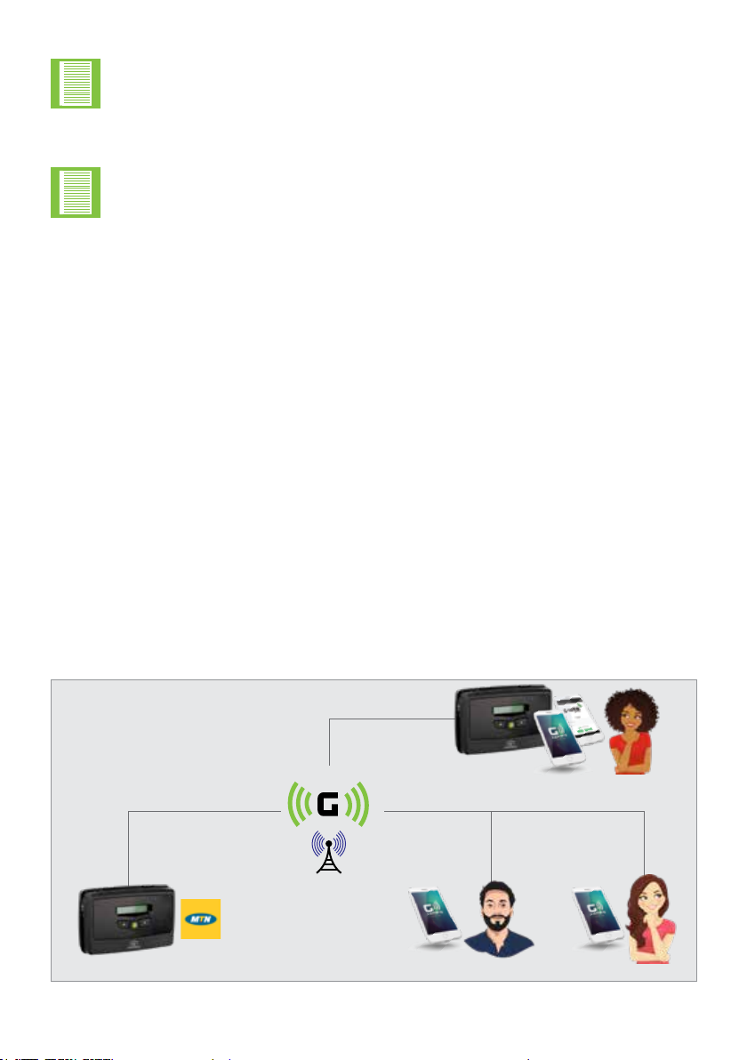
1.2. Dening the WiZo-Link Network
INTRODUCTIONSECTION 1
Between the mobile device controlling the G-ULTRAs and the cellular network,
this path is network agnostic; it does not matter which network is used.
However, between the G-ULTRA and the cellular network, this is MTN network
centric.
The following information is conceptual and will dene and describe some
options users have to create G-Networks.
1.1.1. G-Network of Devices
1.1.1.1. Scenario 1
Lerato
Admin
Network of devices
Complex CandiceScott
FIGURE 2.

page 11 www.centsys.com
NETWORK REDUNDANCYSECTION 2
1.1.1.2. Scenario 2
1.1.1.3. Scenario 3
Candice lives in the same complex as Lerato. Recently, there had been security issues
with the old system, and she was happy to hear that a new system was being installed.
She received a link on WhatsApp directing her to install an app galled G-REMOTE. She
tapped on the link, found herself in the AppStore, and then clicked install. Once the
G-REMOTE app was installed, she opened it, clicked on the name of her complex on the
main screen, and saw a collection of large, easy to read colour-coded buttons. Just then,
her mom messaged her from the gate, and she tapped the easy to see Open Gate button
and could see from her lounge window, the gate opening.
Lerato and Candice were impressed with the way that the new CENTURION products had
improved security at their complex. They decided to install a similar setup at their small
business premises. Thinking it would be dicult, they approached Frank and asked for
help. He said there was no need, as all they needed to do was to install the G-WEB app
on their phone, follow the easy instructions to link the new device, and then to also link
their phone to their G-WEB prole. He then showed them how to link the new, separate
G-ULTRA device so that it displayed in G-REMOTE.
Dumisani spends more time out of the oce, and now Candice can open and close the
gate from her phone. During the day, it has been very convenient to let clients and
suppliers in and out of the premises as the old wired system kept breaking especially
after a lightning storm. Now, the quick response of the remote system has made it easy
and she can open it from wherever she is, as she does not need to go to the front of the
oce to press a button.
It also proved very useful over the weekend when the armed response security needed
to gain entry to the premises, and they were able to 1) open the gate 2) wait on the
response that the alarm had been reset 3) were able to monitor the gate closure
remotely until closed.
Lerato
Users
Admin
Complex
Network of devices
Small business Candice
FIGURE 3.

page 12 www.centsys.com
Before opening the box, you will notice on the side of the box key information you will
require later. They are the following items:
• IMEI Number; this uniquely identies the GSM unit
• Password: this is a 4-digit number that is already congured for the device
Ensure that the ap of the box is retained or that you record the information using your
phone by taking a picture or by recording the information by other means.
The unit is compact but releases easily from the box once you carefully cut through the
tamper-proof seal that protects both sides of the box. If this seal is compromised, return
your purchase.
The following specications describe the Key Features and operating Requirements for
the G-ULTRA.
1. A relay will allow for a higher current load to be switched on using the G-ULTRA
G-ULTRA UNITSECTION 2
The following details pertain to the G-ULTRA; ensure to make note of the items
mentioned.
2.1. Opening the Box
2.2. Unit Description
2.2.1. Technical Specications
2.4.1. Establishing the Network
2. G-ULTRA UNIT
Item Description
Supply Voltage Range 11-24V DC
Maximum Current Draw 300mA @ 12V DC
Input/output Current Rating 50mA (Open Collector)
Relay Contact Current Rating 1A, 30V AC/DC (Resistive)
Input Sense Voltage Range 0-24V DC (0-1.6V Low-input State, 5V-24V
High-input State)
Network Provider MTN (South Africa only)
Number of Congurable IO Channels 4
Number of Relays 21
TABLE 1.

page 13 www.centsys.com
Shown here are the Terminal Block
connections for G-ULTRA. You gain
access to the terminal block by
removing the cover, which lifts free
from the unit’s base
The common standard for wire
colours for a DC connection is red
and black: red positive and black
negative. Following this wiring
convention will make the connections
simpler, and 2-core cabling is readily
available using this scheme.
Shown left is the power connections
which need to be active to be able to
sync the G-ULTRA device.
2.2.2. Terminal Block
2.2.2.1. Power Supply
GND
GND
IO4
IO4
NO
NO
IO1
IO1
NO
NO
COM
COM
IO2
IO2
COM
COM
RELAY 1
RELAY 1
RELAY 2
RELAY 2
NC
NC
IO3
IO3
NC
NC
+ VDC -
+ VDC -
G-ULTRA
G-ULTRA
GND Ground
IO1 Input / Output 1 (Default: Output)
IO2 Input / Output 2 (Default: Output)
IO3 Input / Output 3 (Default: Output)
IO4 Input / Output 4 / Gate Status Input (Default: Output)
NO Relay 1 Normally-open
COM Relay 1 Common
NC Relay 1 Normally-closed
NO Relay 2 Normally-open
COM Relay 2 Common
NC Relay 2 Normally-closed
+ Positive of Power Supply 12-24VDC
- Negative of Power Supply
The G-ULTRA utilises a DC (Direct Current) power supply, with an acceptable input range
from 11 Volts DC to 24 Volts DC. The G-ULTRA can therefore be powered by a battery of
suitable output, or suitable DC Power supply.
• Ensure sucient input voltage is supplied so that the G-ULTRA powers up
correctly
• Do not oversupply the G-ULTRA as this WILL damage the unit
• DO NOT power the unit directly from an Alternating Current (AC), Mains, or
normal household socket supply as this WILL destroy the G-ULTRA
-Ve+Ve
G-ULTRA UNITSECTION 2
TABLE 2.
FIGURE 4.
FIGURE 5.

page 14 www.centsys.com
The battery often used for a
G-ULTRA is a standard 12V 7 Ah,
sealed lead-acid battery. These are
often used in UPS (Uninterruptable
Power Supply) and are inexpensive
and readily available.
With the range of batteries, the
Ampere Hour or Ah rating does
correlate to the physical size of
the battery and for how long the
G-ULTRA could be powered.
The G-ULTRA draws 300 mA at
12V, so 7 Ah / 300mA = 23.3 hours.
Your G-ULTRA in theory would
then have close to 24 hours running
time during load shedding, for
example. This time is theoretical,
as the condition of the battery and
other factors can impact on the
battery, reducing the time it can be
a backup.
As shown in the image below, the
battery is connected in line with the
G-ULTRA and therefore it charges
and is part of the power circuit at
the same time. Good practice would
be to include a diode in-line with the
positive wiring before the battery
and after the power supply. Charge
voltage for a SLA is 13.7V, so to
compensate for the diode which
needs 0.6V to work, your total input
voltage would be 14.3V. The reason
for the diode is that, while the power
supply is active, it is providing power
but when there is a power failure,
the power supply can eectively
become a load and help drain the
battery. The diode protects the
battery and ensures that only the
G-ULTRA is using it.
The G-ULTRA can be powered from a battery backup system in the event of a power
failure, and this can be tied into the Advanced Power features. You have the choice of
two options to power either from a 12V or a 24V battery, and this is within the DC power
supply range of the device.
2.2.2.2. Battery Backup
2.2.2.2.1. Battery Backup
2.2.2.2.2. Wiring Up the Battery
GND IO4 NOIO1 NO COMIO2 COM
RELAY 1 RELAY 2
NCIO3 NC + VDC -
G-ULTRA
-Ve+Ve
When the battery is included, strict adherence to the maximum input voltage
must be applied to avoid overcharging the battery. If overcharged, this can
lead to excessive heat and a potential re hazard.
G-ULTRA UNITSECTION 2
FIGURE 6.
FIGURE 7.

page 15 www.centsys.com
The G-ULTRA oers four individually-congurable channels (IO) and two Relay Outputs
can be mapped to either trigger a notication or activate an output. These are congured
using the G-WEB application or website.
The G-ULTRA’s IO are highly congurable and enable the user to map them internally
to either the IO’s located at positions 1-4 or the mechanical relays at relay output 5 and
6. An input can be congured as a trigger to an output. This can be as simple as a push
button interaction, for example, a security oce pushing a button in an oce to open a
gate or to buzz a door open.
Conguring an input has two main steps; the rst is to congure an IO as an input, which
is done on the IO settings page. The second step, once the IO has its designation, is to
congure the advanced features of the IO on the Advanced IO settings page.
Rise Edge refers to the time it takes for the leading edge of a pulse (voltage or current)
to rise from its minimum to its maximum value. Rise Edge is typically measured from
10% to 90% of the value. Conversely, Fall Edge is the measurement of the time it takes
for the pulse to move from the highest value to the lowest value. In a resistive circuit,
Rise Time values are primarily due to stray capacitance and inductance, which cause a
delay in voltage and/or current until the steady state is reached. In terms of application,
when measuring a waveform on an oscilloscope, the faster the Rise Edge, the more
accurate the measurement.
When using the Rise and Fall elements of an input pulse, it is important to consider how
this may aect the day-to-day operation of the system, and how you wire the push
button in, for example. The two ways would be to:
2.2.3. Inputs / Outputs
Input 4, is a dual-purpose input that can be assigned to monitor the condition or
state of a gate operator of a gate closing. Only Input 4 can be assigned to this
role, and a D-Series Motor controller is used to provide the input data. Input 4 is
congured using the G-WEB application or website. If more than one gate needs
to be monitored, then two G-ULTRAs would be required
2.2.3.1. Working With IO
2.2.3.1.1. Steps to Congure
2.2.3.1.2. Rise and Fall Edges
1. Wire a push button so that it’s normally-closed i.e. there is always power active
on the input until the push button is pressed. The power then goes from high to
low or has a falling edge, i.e. on to o
2. Alternatively, the push button is wired so that the power is only present on the
input when the push button is pushed, and so has a rising edge i.e. o to on
G-ULTRA UNITSECTION 2

page 16 www.centsys.com
TABLE 2
In an ideal world, we would have
clean signals moving between
the switch and the input, but in
the real world owing to electrical
characteristics of materials, transient
power surges and interference, any
number of events can appear like a
valid input signal, but it is not. As
shown in the image below, what is
anticipated by us in the ideal world
is oset by what may happen and a
poorly formed input signal may be
valid or just interference.
A relay is a mechanical component that can be triggered to switch a device on or o
depending on how it is set up and wired.
A relay is a mechanical component that can be triggered to switch a device on or o
depending on how it is set up and wired.
An example is where the G-ULTRA is used to switch a pump on, and it stays on until the
oat mechanism triggers the G-ULTRA to switch the relay o.
Pulsed, is the change from the current state to a new state momentarily or for a short
time and then automatically switches back to the original state.
An example would be a day-night switch, where the motion sensor triggers the relay, but
it only stays on for a few seconds or minutes before switching o regardless of whether
the action which caused the trigger is still active.
Mobile apps have been provided without cost, and these apps enable you to congure
and use a congured device. When you use the mobile apps for monitoring and
conguring the device, no costs to you are incurred for the life of the product, provided
that a CENTURION MTN SIM is used
For costs incurred when making use of SMS notications you will need to purchase
CENTURION tokens via G-WEB
2.2.3.2. Working with Relays
2.2.3.2.1. Latching VS Pulsed
2.3.1. Network Access from the Mobile Apps
IDEAL
REAL
Rising
edge
Time
Falling
edge
2.3. Network Connectivity
CENTURION MTN SIM cards can only be recharged using the G-WEB online
platform or G-WEB mobile app.
G-ULTRA UNITSECTION 2
FIGURE 8.

page 17 www.centsys.com
The unit is supplied with a NANO
SIM card. The SIM card is visible
when the top cover plate is removed,
and the unit tipped to the side. The
SIM card is held in place by a push
to release the SIM cardholder.
The SIM card supplied is an MTN
SIM card, which is contracted via
CENTURION to MTN. The supplied
SIM card is not standard and can
only be used in the G-ULTRA, and
other CENTURION products where
applicable. It cannot be used in
mobile phones or any other standard
mobile device for communication
purposes.
The G-ULTRA has been supplied with a SIM which has been congured to work
exclusively with the MTN network, and this oers many convenient features when
recharging the SIM with tokens. The G-ULTRA is not a networked locked device, and you
can remove the supplied SIM and use a SIM supplied by any of the local South African
networks. If an alternative SIM is used, you will still be able to congure the unit using
G-WEB; however, managing the device’s airtime and network access won’t be available
and will have to be managed externally.
When replacing the SIM card, ensure
to detach the NANO SIM, which is
the innermost detachable section as
shown in the image.
Follow the instructions below to
insert the SIM card.
2.3.2. SIM Card
2.3.3. Alternative Network SIMs
2.3.2.1. Replacing the SIM Card
G-ULTRA Fascia
Main G-ULTRA
Unit
Standard
Micro
Nano
G-ULTRA UNITSECTION 2
FIGURE 10.
FIGURE 11.

page 18 www.centsys.com
Under normal circumstances, the SIM card should function indenitely provided the
G-ULTRA is not subjected to a harsh environment. Harsh environments are ones where
the G-ULTRA is exposed to dust, corrosive chemicals either directly or indirectly through
atmospheric exposure or environments where there is a high degree of static and/or
electrical interference.
However, in the event that the G-ULTRA loses connectivity, and the SIM card is
suspected, the SIM card can be removed and cleaned or replaced. Cleaning would involve
using a normal eraser to remove any carbon or particle build-up. If this does not solve
the connectivity issue, the SIM card may need to be replaced.
Please follow the instructions in the next section on removing and replacing the SIM card.
Removing the SIM card, when required, is performed by doing the following:
Inserting the SIM card, when required, is performed by doing the following:
2.3.4.1. SIM Card Maintenance
2.3.4.2. How to Remove the SIM Card
2.3.4.3. How to Insert the SIM Card
1. Power down the G-ULTRA, then attempt the SIM removal
2. Using the closed edge of a tweezer, press against the at edge of the SIM card. Apply
rm, even pressure
3. A very slight click will be heard and then the SIM card will release
4. Once ejected, use a pair a tweezers to remove from the slot
1. Ensure that the SIM card is orientated correctly. Use the monogrammed image on the
chassis
2. Using a pair of tweezers, insert the SIM card into the slot
3. Using the closed edge of the tweezers along the at edge of the SIM card, push the
SIM card down using rm, even pressure until you feel resistance. If a slight click is
felt and/or heard, then the SIM card is secure
4. Release the pressure from the SIM card and it should now remain in the slot
5. Visually inspect the inserted SIM card and ensure that it has been securely inserted
6. Power up the G-ULTRA
G-ULTRA UNITSECTION 2
2.3.4. Checking or Replacing the SIM Card

page 19 www.centsys.com
2.4. Installing the G-ULTRA
Installing the G-ULTRA requires some degree of technical skill working with tools
to mount the unit onto a solid surface of diering materials. It is advisable to defer
mounting the unit to either trained or experienced personnel if you do not possess the
appropriate know-how.
The G-ULTRA has been designed with quick disassembly and installation in mind. As can
be seen, the G-ULTRA unclips into three separate pieces.
2.4.1. Unit Disassembly
FIGURE 12. PRODUCT IDENTIFICATION
1. Fascia
2. External Antenna Cover
3. Main G-ULTRA Unit
4. Mounting Plate
5. Terminal Blocks
6. Navigation panel
7. LCD Screen
1
3
4
2
5
6
7
While the G-ULTRA is constructed from quality and durable materials, the unit
or its components should not be subjected to an environment of temperature
extremes, highly corrosive chemicals, or noxious environments.
G-ULTRA UNITSECTION 2

page 20 www.centsys.com
2.4.2. Mounting the Unit
With the mounting plate removed, you will notice many mounting positions molded into
the plate.
For ease of installation, we recommend that you use the mounting plate as a template to
mark o the mounting positions.
Please see the following section: Power Supply, for details on the power connections.
To power up the unit, supply the required minimum power to the G-ULTRA and the LCD
screen will switch on displaying the words “G-ULTRA” and the CENTURION logo. This is
the startup screen, and this will be displayed for roughly 10 seconds, and then the Home
Screen will display.
The Home Screen will light up using the LCD backlight and after a short while the
backlight will switch o. The LCD Interface enables you to view the current status of the
G-ULTRA; however, it does not allow you to congure any features from the G-ULTRA
itself.
With the unit now securely mounted, you can proceed with wiring up the unit.
1. Identify a suitable location for
the G-ULTRA, and ensure that
the unit will not be mounted in
the path of any sources of water,
condensation, or mold.
2. Using the mounting plate as a
template, mark o the holes
using a pencil or a sharp object
which will leave a visible mark on
the wall or the surface where the
unit will be mounted. Ensure that
the plate is facing the correct
way i.e. square slot down, as
shown in the image below.
3. Remove the mounting plate
from the surface and use the
appropriate size drill to create
the mounting holes.
4. Once the holes have been drilled,
secure the mounting plate to the
surface and ensure the mounting
plate is sitting ush against the
wall.
5. The main G-ULTRA unit can
now be clipped back into the
mounting plate.
Mounting
Plate
Mounting
Plate
G-ULTRA
Main Unit
Mounting
screws
(Not Supplied)
Wall
anchors
It is not advised that you drill directly through the mounting plate as this may
damage the plate, especially if a mortise drill bit is used.
2.5. Powering Up the G-ULTRA
G-ULTRA UNITSECTION 2
FIGURE 13.
FIGURE 14.
Other manuals for G-ULTRA
1
Table of contents