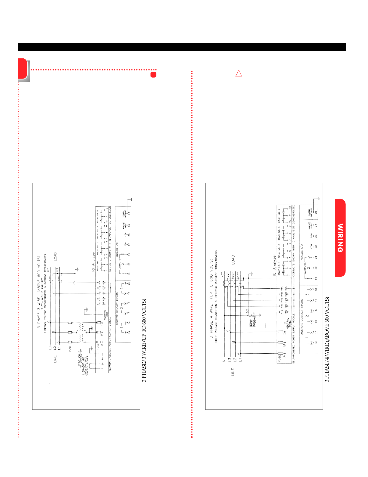
Displayed Information
1Line to neutral values do not apply for 3-wire system, use sys-
tem values.
2Fundamental watts to VA.
3Total rms watts to VA.
4 K-Factor: A derating factor that is essentially the sum of the
squares of individual harmonic currents times the squares of
their harmonic number (i.e., multiples of fundamental). One
for each current is displayed with largest recorded in Event
metered data.
5CBEMA Factor: A transformer harmonic derating factor defined
as a pure sine wave’s crest factor (1.414) divided by the mea-
sured crest factor.
6Crest Factor: The ratio of peak current to rms current.
Display Type Comments
Current
Voltage
Power
Energy
Demand
Power Factor
Frequency
% THD
Distortion Factor
Custom
• Phase A, B, C, Average
• Neutral
• Ground
(separate CT inputs for each)
• Phase A-B, B-C, C-A, Average
• Phase A-N, B-N, C-N, Average
• Neutral - Ground
• System
1and Phase A, B, C
• Real (Watts)
• Reactive (vars)
• Apparent (VA)
• Forward, Reverse, Net
• Real (kWh)
• Reactive (kvarh)
• Apparent (kVAh - Net only)
• System Current (A)
• System Real Power (kW)
• System Reactive Power (kvar)
• System Apparent Power (kVA)
•System and Phase A, B, C
•Displacement2
•Apparent3
•Hz
•Time
•Date
•Currents
Phase A, B, C
Neutral
•Voltages
Phase A-B, B-C, C-A
Phase A-N, B-N, C-N
•K-Factor4(of Event)
• CBEMA Derating Factor5(THDF)
•Crest Factor6
•Discrete Input and Output Status
•Analog Input Reading
•User can program two screens to
display any combination of seven
Meter Menu parameters per
screen via the Custom Screens
option under Display Manager.
(PGM/DISPMGR/CUST)
7
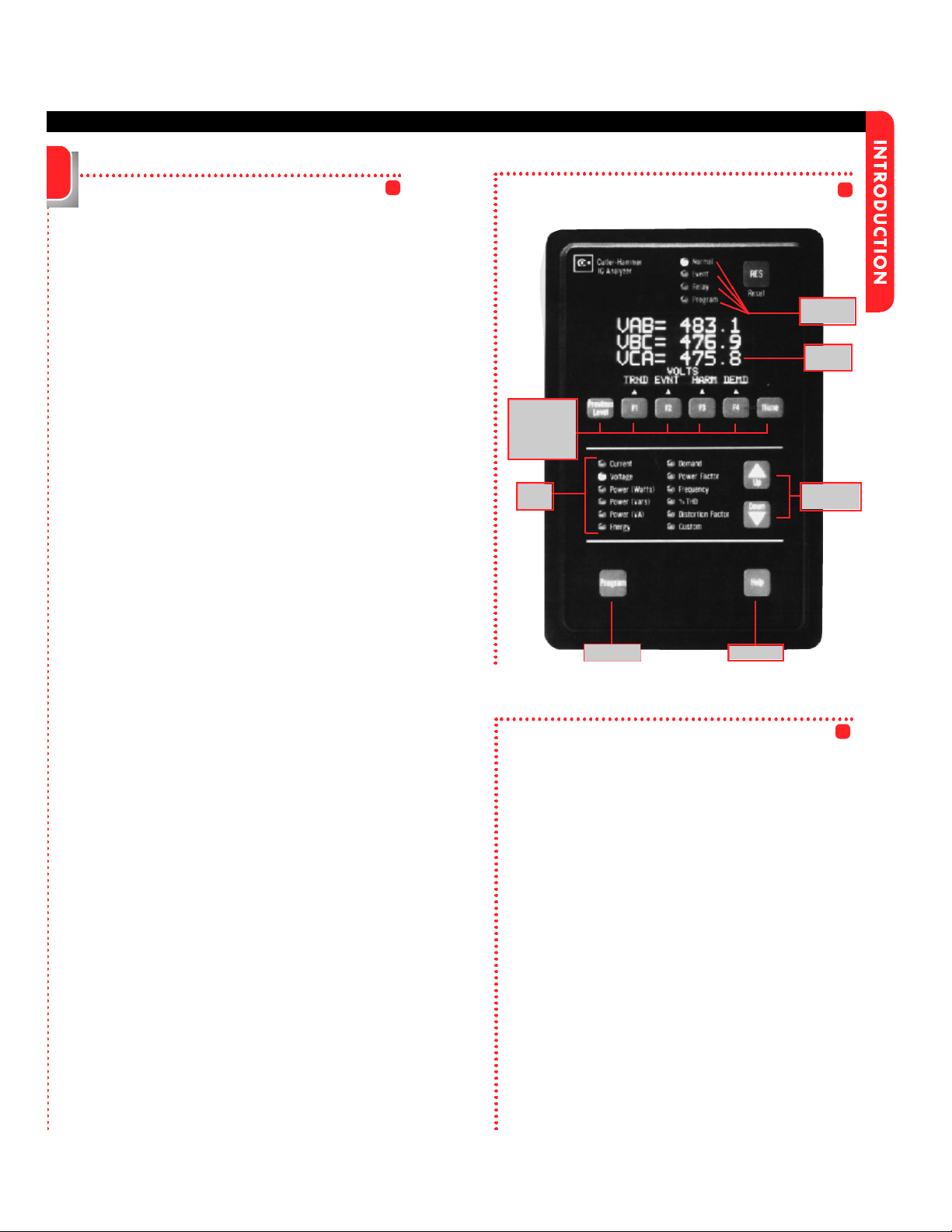
Display Mode:
(USER’S MANUAL SECTIONS 5-2)
The IQ Analyzer monitors and displays a compre-
hensive list of metered parameters. The Meter Menu
provides easy access (using Up/Down PBs) to the
most commonly used metered parameters:
Current Voltage Power (Watts)
Power (Vars) Power (VA) Energy
Demand Power Factor Frequency
%THD Distortion Factor Custom
Several parameters will require multiple screens for
complete display of all available information.
Up/Down will toggle through all displays.
Analysis Modes:
(USER’S MANUAL SECTION 5-7)
Analysis screens show detailed system information
relative to the selected category. All historical and
event information is accessed in the analysis modes.
Trend Analysis Event Analysis
Harmonic Analysis Demand Analysis
Program Mode:
(USER’S MANUAL SECTION 5-4)
This password protected mode is used to configure
the Unit. Use Program Mode to specify General
Setup Settings and for advanced features.
Reset Mode:
(USER’S MANUAL SECTION 5-10)
Using this password protected mode, the operator
can reset or clear certain items such as Min/Max val-
ues, Alarm Triggers, Relays and Peak Demand
Values.
Help Mode:(USER’S MANUAL SECTION 5-3)
The IQ Analyzer displays various Help screens and
useful information relating to device operation, pro-
gramming and troubleshooting.
Modes of Operation
Communications
(USER’S MANUAL SECTIONS 5-8)
TheIQ Analyzer is an IMPACC (Integrated
Monitoring Protection and Control
Communications) compatible device. It can be
remotely monitored, controlled and programmed
when equipped with the communications option.
The small, addressable communications module
(IPONI), is mounted to the back of the IQ Analyzer.