CE+T Power SIERRA 25-48/230 User manual

www.cet-power.com
Belgium, China, India, Luxembourg, Malaysia, Russia, Turkey, United Kingdom, United States, Australia & Germany
Copyright © 2013. Construction electroniques & telecommunications S.A.
All rights reserved. The contents in document are subject to change without notice.
The products presented are protected by several international patents and trademarks.
Address: CE+T S.a, Rue du Charbonnage 12, B 4020 Wandre, Belgium
www.cet-power.com - info@cet-power.com
SIERRA 25 - 48/230
User Manual V1.0
THE NEW GENERATION OF POWER CONVERTERS
• DUAL AC AND DC OUTPUT CONVERTER
Commercial Power as default source
• AC AND DC BACKUP IN A DC ENVIRONMENT
Leverage your existing DC infrastructure
• ONE STOP SHOP
Wide output power range
• HARSHEST AC INPUT CONDITIONS
Without compromising the quality of the AC output

2 – Sierra 25 - 48/230 VAC – User Manual – v1.0
Table of content
1. CE+T Power at a glance......................................................................................................................... 6
2. Abbreviations......................................................................................................................................... 7
3. Warranty and Safety Conditions ............................................................................................................. 8
3.1 Disclaimer................................................................................................................................... 8
3.2 Technical care............................................................................................................................. 8
3.3 Installation .................................................................................................................................. 9
3.3.1 Handling......................................................................................................................... 9
3.3.2 Surge and transients ...................................................................................................... 10
3.3.3 Other.............................................................................................................................. 10
3.4 Maintenance .............................................................................................................................. 10
3.5 Replacement and Dismantling..................................................................................................... 10
4. ECI TECHNOLOGY................................................................................................................................... 11
4.1 EPC mode ................................................................................................................................... 12
4.2 Back up mode............................................................................................................................. 12
5. Building Blocks ...................................................................................................................................... 13
5.1 Sierra 25 - 48/230 ...................................................................................................................... 13
5.1.1 Specifications................................................................................................................. 13
5.2 Sub-rack..................................................................................................................................... 15
5.3 Controller - Inview S.................................................................................................................... 15
5.3.1 Inview S - Connections................................................................................................... 15
5.4 Measure Box Battery (MBB)......................................................................................................... 16
6. Accessories ........................................................................................................................................... 17
6.1 Cabinet ....................................................................................................................................... 17
6.2 Manual By-Pass .......................................................................................................................... 17
6.3 AC Distribution Unit ..................................................................................................................... 17
6.3.1 Miniature Circuit Breakers.............................................................................................. 17
6.3.2 MCCB............................................................................................................................. 18
7. System Design....................................................................................................................................... 19
7.1 A la Carte .................................................................................................................................... 19
8. Installation of Sierra Shelf ...................................................................................................................... 20
8.1 Mounting kit for Sierra shelf ........................................................................................................ 20
8.2 Electrical installation for Sierra shelf............................................................................................ 21
8.2.1 Pre requisites ................................................................................................................. 21
8.2.2 Terminations .................................................................................................................. 22
8.2.3 Grounding ...................................................................................................................... 22
8.2.4 DC connection................................................................................................................ 22
8.2.5 AC Input connection ....................................................................................................... 22
8.2.6 AC Output connection..................................................................................................... 23
8.2.7 Signalling ....................................................................................................................... 23

3 – Sierra 25 - 48/230 VAC – User Manual – v1.0
8.2.8 Remote ON/OFF.............................................................................................................. 23
8.2.9 Internal CAN BUS A and B............................................................................................... 24
8.2.10 Shelf rear cover.............................................................................................................. 24
9. Installation of Cabinet (A la Carte) .......................................................................................................... 25
9.1 Unpacking the system ................................................................................................................. 25
9.2 Module packing........................................................................................................................... 25
9.3 Removing the cabinet rear protection .......................................................................................... 26
9.4 Hardware Connections ................................................................................................................ 26
9.5 Electrical installation ................................................................................................................... 27
9.5.1 Positioning ..................................................................................................................... 27
9.5.2 Cabling........................................................................................................................... 28
9.5.3 Grounding ...................................................................................................................... 28
9.5.4 Surge Suppression ......................................................................................................... 28
9.5.5 AC Input (X2) and Output (X4) ......................................................................................... 28
9.5.6 DC (X1) .......................................................................................................................... 30
9.5.7 Connection table – DC 48 Vdc (X1) ................................................................................. 30
9.5.8 Connection table – AC Input (X2) & Output (X4)............................................................... 30
9.5.9 Signalling ....................................................................................................................... 31
10. Operation.............................................................................................................................................. 33
10.1 Converter module........................................................................................................................ 33
10.2 Inview S - LCD Display ................................................................................................................ 34
10.2.1 Menu structure............................................................................................................... 34
10.2.2 Interface Areas ............................................................................................................... 34
10.2.3 Inview S - LED indications.............................................................................................. 35
10.3 Inview S and Inview S Slot - Web Interface .................................................................................. 35
10.3.1 Login.............................................................................................................................. 35
10.3.2 Interface Areas ............................................................................................................... 36
11. Inserting/removing/replacing - modules................................................................................................. 38
11.1 Sierra Converter .......................................................................................................................... 38
11.1.1 Removal......................................................................................................................... 38
11.1.2 Inserting......................................................................................................................... 38
11.2 Inview S ...................................................................................................................................... 39
11.2.1 Panel Mounting .............................................................................................................. 39
11.3 Fan replacement ......................................................................................................................... 39
12. AC Output Distribution........................................................................................................................... 41
12.1 Miniature Circuit breaker Installation/Removal............................................................................. 41
12.2 MCCB.......................................................................................................................................... 41
13. Manual By-Pass (MBP).......................................................................................................................... 42
13.1 Pre-requisites.............................................................................................................................. 42
13.2 MBP Auxiliary connection ............................................................................................................ 42
13.3 Manual Bypass operation ............................................................................................................ 43
13.3.1 MBP - Single rotary switch............................................................................................. 43
13.3.2 MBP - Three individual switches..................................................................................... 44

4 – Sierra 25 - 48/230 VAC – User Manual – v1.0
14. Finishing................................................................................................................................................ 45
15. Commissioning ...................................................................................................................................... 46
15.1 Check list .................................................................................................................................... 47
16. Trouble Shooting and Defective Situations Fixing.................................................................................... 48
16.1 Trouble Shooting ......................................................................................................................... 48
17. Maintenance.......................................................................................................................................... 49
17.1 Access Inview S with Laptop ....................................................................................................... 49
17.2 Manual check.............................................................................................................................. 49
17.3 Optional ...................................................................................................................................... 49
17.4 Manual By-Pass ......................................................................................................................... 49
18. Defective modules ................................................................................................................................. 50
19. Appendix................................................................................................................................................ 51
19.1 Mains connection, Single phase .................................................................................................. 51
19.2 Mains connection, Three phases.................................................................................................. 52
19.3 Inview S with MBB - Wiring diagram............................................................................................ 53
19.4 Modules - Parameter List ............................................................................................................ 54

Release Note:
Version Release date
(DD/MM/YYYY) Modified page number Modifications
1.0 23/10/2019 - First release of the Manual.
5 – Sierra 25 - 48/230 VAC – User Manual – v1.0

1. CE+T Power at a glance
CE+T Power designs, manufactures and markets a range of products for industrial operators with mission critical
applications, who are not satisfied with existing AC backup systems performance and related maintenance costs.
Our product is an innovative AC backup solution that unlike most used UPS’s
•Maximizes the operator’s applications uptime;
•Operates with lowest OPEX;
•Provides best protection to power disturbances;
•Optimizes footprint.
Our systems are:
•Modular
•Truly redundant
•Highly efficient
•Maintenance free
•Battery friendly
CE+T puts 60+ years expertise in power conversion together with worldwide presence to provide customized solutions
and extended services 24/7 – 365 days a year.
6 – Sierra 25 - 48/230 VAC – User Manual – v1.0
CE+T Power at a glance

2. Abbreviations
ECI Enhanced Conversion Innovation
EPC Enhanced Power Conversion
REG Regular
DSP Digital Signal Processor
AC Alternating current
DC Direct current
PE Protective Earth (also called Main Protective Conductor)
N Neutral
PCB Printed Circuit Board
TRS True Redundant Structure
PWR Power
ESD Electro Static Discharge
MET Main Earth Terminal
MBP Manual By-pass
MBB Measure Box Battery
TCP/IP Transmission Control Protocol/Internet Protocol
USB Universal Serial Bus
LAN Local Access Network
ETH Ethernet
SNMP Simple Network Management Protocol
HTTP HyperText Transfer Protocol
HTTPS Secure HyperText Transfer Protocol
NTP Network Time Protocol
MIB Management Information Base
DHCP Dynamic Host Configuration Protocol
7 – Sierra 25 - 48/230 VAC – User Manual – v1.0
Abbreviations

3. Warranty and Safety Conditions*
WARNING:
The electronics in the power supply system are designed for an indoor, clean environment.
When installed in a dusty and/or corrosive environment, indoor, it is important to:
•Install an appropriate filter on the enclosure door, or on the room’s air conditioning system.
•Keep the enclosure door closed during operation.
•Replace the filters on a regular basis.
Important Safety Instructions, Save These Instructions.
3.1 Disclaimer
•The manufacturer declines all responsibilities if equipment is not installed, used or operated according to the
instructions herein by skilled technicians according to local regulations.
•Warranty does not apply if the product is not installed, used or handled according to the instructions in the
manual.
•This equipment is shipped with a SHOCKWATCH monitor. If the SHOCKWATCH shows that the equipment was
exposed to excessive force the warranty will be void.
3.2 Technical care
•This electric equipment can only be repaired or maintained by a “qualified employee” with adequate training.
Even personnel who are in charge of simple repairs or maintenance are required to have knowledge or
experience related to electrical maintenance.
•Please follow the procedures contained in this Manual, and note all the “DANGER”, “WARNING” AND “NOTICE”
marks contained in this Manual. Warning labels must not be removed.
•Qualified employees are trained to recognize and avoid any dangers that might be present when working on or
near exposed electrical parts.
•Qualified employees know how to lock out and tag out machines so the machines will not accidentally be turned
on and injure employees working on them.
•Qualified employees also know safety related work practices, including those by OSHA and NFPA, as well as
knowing what personal protective equipment should be worn.
•All operators are to be trained to perform the emergency shut-down procedure.
•Never wear metallic objects such as rings, watches, or bracelets during installation, service and maintenance of
the product.
•Maximum operating ambient temperature is 40°C (104°F).
•Insulated tools must be used at all times when working with live systems.
•When handling the system/units pay attention to sharp edges.
•This product is suitable for use in a computer room.
* These instructions are valid for most CE+T Products/Systems. Some points might however not be valid for the product
described in this manual.
8 – Sierra 25 - 48/230 VAC – User Manual – v1.0
Warranty and Safety Conditions

3.3 Installation
•This product is intended to be installed only in restricted access areas as defined by local regulations and in
accordance with the National Electric Code, ANSI/NFPA 70, or equivalent agencies.
•The Converter System may contain output over current protection in the form of circuit breakers. In addition
to these circuit breakers, the user must observe the recommended upstream and downstream circuit breaker
requirements as defined in this manual.
•Please use extreme caution when accessing circuits that may be at hazardous voltages or energy levels.
•The modular converter rack is a dual input power supply. The complete system shall be wired in a way that both
input and output leads can be de-energized when necessary.
•REG systems and EPC systems that have no AC input wired and connected can be seen as independent power
sources. To comply with local and international safety standards N (input) and PE shall be bonded. The bonded
connection between N (input) and PE must be removed once the AC input is connected.
•AC and DC circuits shall be terminated with no voltage / power applied (de-energized).
•The safety standard IEC/EN62040-1-1 requires that, in the event of an output short circuit, the converter must
disconnect in 5 seconds maximum. The parameter can be adjusted on Inview; however, if the parameter is set at
a value > 5 seconds, an external protection must be provided so that the short circuit protection operates within
5 seconds. Default setting is 60 seconds.
•The system is designed for installation within an IP20 environment. When installed in a dusty or humid
environment, appropriate measures (air filtering) must be taken.
•Environment Conditions:
Storage Conditions: -40 to 70°C
Relative Humidity: 95%, non-condensing
Altitude above sea without de-rating: Less than 1500 m
Greater than 1500 m – de-rating at 0.8% per 100 m
•All illustrations in the manual are for general reference, refer to the technical drawing which is received along
with the system for exact information.
3.3.1 Handling
•The cabinet shall not be lifted using lifting eyes.
•Remove weight from the cabinet by unplugging the converters. Mark converters clearly with shelf and position
for correct rebuild. This is especially important in dual or three phase configurations.
•Empty converter positions must not be left open. Replace with module or blank cover.
9 – Sierra 25 - 48/230 VAC – User Manual – v1.0
Warranty and Safety Conditions

3.3.2 Surge and transients
The mains (AC) supply of the modular converter system shall be fitted with Lightning surge suppression and Transient
voltage surge suppression suitable for the application at hand. Manufacturer’s recommendations of installation shall
be adhered to. Selecting a device with an alarm relay for function failure is advised.
Indoor sites are considered to have a working lightning surge suppression device in service.
•Indoor sites Min Class II.
•Outdoor sites Min Class I + Class II or combined Class I+II. The modular converter system/rack can reach
hazardous leakage currents. Grounding must be carried out prior to energizing the system. Grounding shall be
made according to local regulations.
Note:
Choosing and installing surge arrestors must obey to precise technical rules. Distance to equipment to protect, cable
gage and cable routing have significant influence on proper device service.
Some areas are more susceptible to be hit by electrical strikes, especially when altitude increases.
Good earthing is also crucial for surge arrestors to work properly.
CE+T declines any liability in regard to damaged caused to equipment not correctly or not sufficiently protected.
3.3.3 Other
•Insulation test (Hi-Pot) must not be performed without instructions from the manufacturer.
3.4 Maintenance
•The converter system/rack can reach hazardous leakage currents. Earthing must be carried out prior to
energizing the system. Earthing shall be made according to local regulations.
•Prior to any work conducted to a system/unit, make sure that AC input voltage and DC input voltage are
disconnected.
•Prior to accessing the system or modules, make sure all source of supply is disconnected.
CAUTION – Risk of electric shock. Capacitors store hazardous energy. Do not remove cover until 5 minutes after
disconnecting all sources of supply..
•Some components and terminals carry high voltage during operation. Contact may result in fatal injury.
3.5 Replacement and Dismantling
•ESD Strap must be worn when handling PCB’s and open units.
•The converter system/rack is not supplied with internal disconnect devices on input nor output.
•CE+T cannot be held responsible for disposal of the converter system and therefore the customer must
segregate and dispose of the materials which are potentially harmful to the environment, in accordance with the
local regulations in force in the country of installation.
•If the equipment is dismantled, to dispose of its component products, you must comply with the local regulations
in force in the country of destination and in any case avoid causing any kind of pollution.
To download the latest documentation and software, please visit our website at
www.cet-power.com
10 – Sierra 25 - 48/230 VAC – User Manual – v1.0
Warranty and Safety Conditions

11 – Sierra 25 - 48/230 VAC – User Manual – v1.0
ECI TECHNOLOGY
4. ECI TECHNOLOGY1
Sierra module built with ECI technology and it is a triple port converter. This module deliver pure sinusoidal output and
ripple free DC output from AC mains or battery.
The below block diagram gives an explicit description of the topology and its operation.
ECI technology has AC to DC, DC to AC, and DC to DC converters to provide constant and disturbance-free output
power regardless of the input source.
The power flows either from AC or DC source under the control of the DSP controller. Thanks to internal energy
buffering for transferring the load between two input sources by 0 ms.
ECI can detect short circuit conditions at the AC output level and start the BOOST mode function. This mode will
provide 8x of the nominal current to clear the fault within 20ms, and thus keeping other critical loads in operation.
Sierra module works on True Redundant Structure (TRS) that features decentralized, independent logic, and redundant
communication bus.
Each Sierra module has three levels of protection, and it will help to isolate from other modules in case of any fault in
the corresponding module. Due to this functionality in each module, it provides no single point of failure in modular
systems.
The Sierra modular systems provide quality output power with higher efficiency.
1 Information and data given in this chapter is intended to serve as an overview of the ECI Technology. Detailed features and parameters for each individual
module type in the range may differ and should be referred to in the dedicated data sheet.

12 – Sierra 25 - 48/230 VAC – User Manual – v1.0
ECI TECHNOLOGY
4.1 EPC mode
In EPC mode, the AC Mains is the primary source and DC source works as a backup. When AC mains is present, the
sierra module takes energy from the AC source and feed to:
•AC Load via a double conversation to provide a pure sine wave.
•DC load and also charges the battery with a regulated DC.
AC IN AC Out
DC Out
Battery
The total output power of a module can be shared between the AC load, DC load and charging power based upon the
requirement.
If the AC source is not present, the module seamlessly switches to DC source without impacting the critical loads and
resumes to EPC mode once AC source returns. The transfer time between AC to DC and DC to AC is 0 ms.
The EPC mode provides a higher efficiency of ≥ 96% without compromising the purity of the output sine wave.
4.2 Back up mode
In back up mode, module operates in DC source and feed to:
•AC Load via a double conversation to provide a pure sine wave.
•DC load directly.
AC IN AC Out
DC Out
Battery

13 – Sierra 25 - 48/230 VAC – User Manual – v1.0
Building Blocks
5. Building Blocks
5.1 Sierra 25 - 48/230
Telecom / Datacom: Input 48 Vdc
230 Vac, 50/60 Hz
Output 230 Vac and 48 Vdc
Power 3000 VA / 2400 W
•The Sierra converter is a triple port converter.
•Each converter can supply 2400 W on any DC, AC or combination of both AC and DC output ports. AC output
load is the highest priority. Even if AC output is fully loaded (2400 W), still 200 W is available for DC output.
•Hot swappable and hot pluggable.
•The front LED’s indicate the converter status and output power.
•Module is equipped with soft start.
•Fan is equipped with alarm and run time meter. The fan is field replaceable.
•435 mm (D) x 102 mm (W) x 88 mm (H).
•5 Kg.
5.1.1 Specications
Model Sierra 25 - 48/230
Part Number: Module / shelf T721730201 / T724730000
Cooling Fan forced cooling
MTBF 240 000 hrs (MIL-217IF)
Dielectric strength DC/AC 4300 Vdc
RoHS Compliant
Operating T° / Relative Humidity (RH) non-condensing
Tested according ETS300-019-2-3 Class 3.1
-20°C to 65°C, power de-rating from 40°C to 65°C / Max
RH 95% for 96 hours per year
Storage T° / Relative Humidity (RH) non-condensing Tested according ETS300-019-2-1 Class 1.2
-40°C to 70°C / Max RH 95% for 96 hours per year
Public transport T°/Relative Humidity (RH) non-
condensing
Tested according ETS300-019-2-2 Class 3.1
-40°C to 70°C / Max RH 95% for 96 hours per year
Material (casing) Zinc coated steel
AC Input Data
Nominal voltage / current 230 Vac / 11.7 A
Voltage range 150 - 265 Vac (De-rating from 185 to 150 Vac)
Brownout 1600 W @ 150 Vac / 2400 W @ 190 Vac linear decreasing
Power factor / THD > 0.99 / < 3%
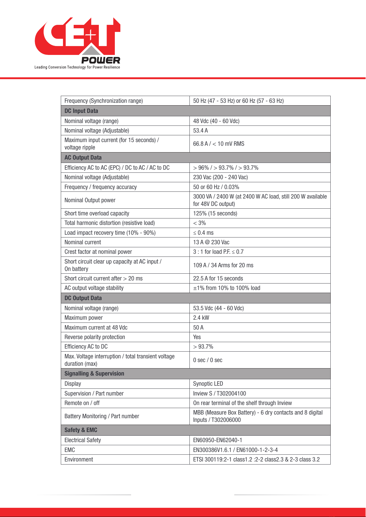
Frequency (Synchronization range) 50 Hz (47 - 53 Hz) or 60 Hz (57 - 63 Hz)
DC Input Data
Nominal voltage (range) 48 Vdc (40 - 60 Vdc)
Nominal voltage (Adjustable) 53.4 A
Maximum input current (for 15 seconds) /
voltage ripple 66.8 A / < 10 mV RMS
AC Output Data
Efficiency AC to AC (EPC) / DC to AC / AC to DC > 96% / > 93.7% / > 93.7%
Nominal voltage (Adjustable) 230 Vac (200 - 240 Vac)
Frequency / frequency accuracy 50 or 60 Hz / 0.03%
Nominal Output power 3000 VA / 2400 W (at 2400 W AC load, still 200 W available
for 48V DC output)
Short time overload capacity 125% (15 seconds)
Total harmonic distortion (resistive load) < 3%
Load impact recovery time (10% - 90%) ≤ 0.4 ms
Nominal current 13 A @ 230 Vac
Crest factor at nominal power 3 : 1 for load P.F. ≤ 0.7
Short circuit clear up capacity at AC input /
On battery 109 A / 34 Arms for 20 ms
Short circuit current after > 20 ms 22.5 A for 15 seconds
AC output voltage stability ±1% from 10% to 100% load
DC Output Data
Nominal voltage (range) 53.5 Vdc (44 - 60 Vdc)
Maximum power 2.4 kW
Maximum current at 48 Vdc 50 A
Reverse polarity protection Yes
Efficiency AC to DC > 93.7%
Max. Voltage interruption / total transient voltage
duration (max) 0 sec / 0 sec
Signalling & Supervision
Display Synoptic LED
Supervision / Part number Inview S / T302004100
Remote on / off On rear terminal of the shelf through Inview
Battery Monitoring / Part number MBB (Measure Box Battery) - 6 dry contacts and 8 digital
Inputs / T302006000
Safety & EMC
Electrical Safety EN60950-EN62040-1
EMC EN300386V1.6.1 / EN61000-1-2-3-4
Environment ETSI 300119:2-1 class1.2 :2-2 class2.3 & 2-3 class 3.2
14 – Sierra 25 - 48/230 VAC – User Manual – v1.0
Building Blocks

5.2 Sub-rack
•The Sierra shelf shall be integrated in min 600 mm deep cabinets, Inch/ETSI mounting.
•The Sierra shelf house max four (4) inverter modules.
•The Sierra shelf is designed with individual DC input / output, Common AC input and Common AC output.
•Optional rear cover for IP 20 in open rack.
•Max 12 kVA per shelf.
•480 mm (D) x 19” (W) x 2U (H).
•6 Kg empty.
5.3 Controller - Inview S
Inview S is an advanced monitoring and controller unit for Bravo 25, Bravo 10, Sierra 25, and Sierra 10 power
systems. It allows the user to easily access the system information through inbuilt powerful touch screen graphic
display. In addition to the touch screen display, the user can also access the system information through the web
interface and SNMP protocol.
The Inview S interface provides the user to access the configuration and setup files of the modules in the system. Also,
it is a controller for DC regulation.
Inview S can monitor up to 32 inverters/converters and featured with:
•LCD touch screen display
•2 Digital Inputs
•2 Output Relay contacts
•Records 5000 events as FIFO
5.3.1 Inview S - Connections
Inview S is composed of multiple network ports and inbuilt free potential contacts.
C
-
C
+
-
NC
+Digital Input 2
Digital Input 1
Output Relay 2
Output Relay 1
Power 12 Vdc
NC
PE
NO
-
NO
+
CAN
iso RS485
ETH
USB
CE+T COM
•CE+T COM port is dedicated to establish connection between Inview S and Sierra - shelf.
•ETH port is used for network connectivity and user can access the system information in the web interface.
•CAN / iso RS485 is used share the system (DC) information to MBB (Measure Box Battery).
15 – Sierra 25 - 48/230 VAC – User Manual – v1.0
Building Blocks

•USB port is used to access the Inview S configuration and setup files.
•Digital Inputs (D1 and D2): Two potential free Digital Inputs are available for customer connections.
Digital Input 1 is assigned for MBP operation if used.
Digital Input 2 is assigned for Surge Arrester if used.
•Output Relays (K1 and K2): Two output relays are available and can be used for Major and Minor Alarms
•Power: The unregulated separate +12 V power supply is required for powering Inview S and this power should
not be shared with other devices. (CET can provide Auxiliary Power Supply converter and the part number is
T602004120).
5.4 Measure Box Battery (MBB)
Measure Box Battery is a unit which monitors the Battery. It is composed of multiple digital inputs and analog outputs.
They are used for:
•Battery management
Voltage (V1 to V3)
Current (I1 to I3)
Temperature (T1 and T2)
Driving the Low Voltage Disconnection
•8 Digital Input (D1 to D8)
•6 Output Relay (k1 to K6)
16 – Sierra 25 - 48/230 VAC – User Manual – v1.0
Building Blocks

6. Accessories
6.1 Cabinet
Powder coated (RAL 7024), 19 inch Flat Pack cabinet with 600 x 600 mm foot print. Cabinet designed for top cabling
or bottom cabling.
•1100 mm (600 x 600 mm) 21U
•1800 mm (600 x 600 mm) 37U
•2100 mm (600 x 600 mm) 44U
The cabinet comes with a separable top cover to facilitate cabling. Tie strap support at cable entrance/exit.
Door accessory optional.
6.2 Manual By-Pass
The manual by pass operates via manually operated switches to create a short circuit from the
AC main input directly to the output AC distribution. Standard manual by-pass is “Make before
Break”. When engaged or disengaged, no disturbance is transmitted to the load.
When MBP is engaged, inverter modules are switched off and can be removed without
impacting the load. The battery supply is not physically disconnected. After disconnecting the
battery supply (by opening the battery breakers), the shelf section is safe for maintenance.
Warning: When the system is in by-pass, the load is subjected to AC main disturbances. Before
engaging manual bypass, make sure the voltage difference between AC IN and AC OUT should be
less than 5 Vac to limit the inrush current.
6.3 AC Distribution Unit
6.3.1 Miniature Circuit Breakers
The standard AC output distribution unit is designed with a 35 mm
DIN rail, Multi Clip termination board and N/PE copper terminal
bars, and built as a part of the cabinet.
The Multi Clip offers unique flexibility during installation and
expansion. The terminals are spring loaded and adapt contact
pressure to the size of conductor. Only one cable can be inserted
per spring loaded terminal.
The AC distribution unit is available with 1 pole, 2 pole or 3 poles.
Max current per AC DU is 200 A, max current per terminal
connector is 40 A. Two adjacent terminal connectors shall be used
for 63 A breakers.
17 – Sierra 25 - 48/230 VAC – User Manual – v1.0
Accessories

If an alarm is required for AC output breakers, a help contact attached to each individual breaker is used (OF or SD).
The alarm function is common and uses one of the digital inputs on the control unit. The help contact limits the
breakers quantity.
Single pole Double pole Three pole
w/o help
contact
With help
contact OF/
SD
w/o help
contact
With help
contact OF/
SD
w/o help
contact
With help
contact OF/
SD
Up to 40A 24 16 12 9 8 6
6.3.2 MCCB
AC output distribution via MCCB in the range
up to 400 A (1p, 2p or 3p).
Max two MCCB per inverter cabinet.
18 – Sierra 25 - 48/230 VAC – User Manual – v1.0
Accessories

7. System Design
7.1 A la Carte
The A la Carte is pre-assembled and configured as a single phase or three phase system. The system comprises
cabinet, converter sub rack, converter modules, manual by-pass, monitor device and output distributions.
Single phase system accommodates 1 to 32 modules and provides maximum 96 kVA.
Three phase system accommodates 3 to 30 modules and provides maximum 90 kVA.
Sierra system featured with:
•Dual input (AC & DC).
•Dual output for AC and DC loads.
•More than 96% efficiency during normal operation (EPC).
•Pure sinusoidal AC output and ripple free DC output.
•Seamless transfer (0 ms) between primary and secondary source of supply.
•No single point of failure.
•Flexible output distribution.
•True modularity, redundancy and hot-swappable.
Optional
•Manual by-pass
•AC output distribution
•DC distribution
•Battery fuses
•Battery LVD
•Surge arresters
•Door
19 – Sierra 25 - 48/230 VAC – User Manual – v1.0
System Design

8. Installation of Sierra Shelf
•Read safety instructions prior starting any work.
•Do not attempt to use lifting eyes to erect the cabinet.
•System is preferable handled without modules.
•Pay attention to the module position, make sure that modules are repositioned in the same slot.
•In three phase systems, the modules are configured as per phase 1 (A, R), phase 2 (B, S) and phase 3 (C, T). As
long as the system is not in operation, make sure that modules from one phase are not mixed with modules
from another phase.
(When the system is running, modules can be moved from one phase to another without issue.)
8.1 Mounting kit for Sierra shelf
The fixing brackets, together with the sliders, allow for different cabinet depths.
1Fixing brackets - 4 Nos
2Slider - 2 Nos
3Mounting screws - 12 Nos
4Cage nuts - 12 Nos
Assemble the sliders and adjust the length to suit
the mounting depth.
Fix cage nuts (4) in the cabinet front and rear
frame of the left and the right side.
Fix the left and right slider of the cabinet with the
supplied screws (3).
20 – Sierra 25 - 48/230 VAC – User Manual – v1.0
Installation of Sierra Shelf
This manual suits for next models
2
Table of contents
Other CE+T Power Media Converter manuals

Popular Media Converter manuals by other brands


SOMFY
SOMFY animeo 1860125 installation guide

Transition Networks
Transition Networks M/GE-SW-SFP-01-U Series user guide

BARIX
BARIX Extreamer P5 product manual

ZyXEL Communications
ZyXEL Communications WHD6215 Brochure & specs

TR-Electronic
TR-Electronic CDH 75 M user manual

DVTEL
DVTEL ioimage trk1 installation manual


