EEG HD1492 User manual
EEG HD1492
HD Encoder Frame Card
Product Manual
EEG Enterprises, Inc.
586 Main Street
Farmingdale, New York 11735
TEL: (516) 293-7472 FAX: (516) 293-7417
Copyright © EEG Enterprises, Inc. 2018
All rights reserved.

HD1492 HD Encoder Frame Card
Contents
1 Introduction 3
1.1 Product Description . . . . . . . . . . . . . . . . . . . . . . . 3
2 Installation 4
2.1 Rear Modules . . . . . . . . . . . . . . . . . . . . . . . . . . . 4
2.1.1 Single-Width Rear Module . . . . . . . . . . . . . . . . 4
2.1.2 Double-Width Rear Module . . . . . . . . . . . . . . . . 6
3 HD1492 Operation 8
3.1 Front Panel . . . . . . . . . . . . . . . . . . . . . . . . . . . . 8
3.2 DashBoard Menus . . . . . . . . . . . . . . . . . . . . . . . . 8
3.2.1 System . . . . . . . . . . . . . . . . . . . . . . . . . . . 11
3.2.2 iCap™ . . . . . . . . . . . . . . . . . . . . . . . . . . . . 12
3.2.3 Encoding . . . . . . . . . . . . . . . . . . . . . . . . . . 14
3.2.4 SCTE-104 . . . . . . . . . . . . . . . . . . . . . . . . . . 16
3.2.5 TCP/IP . . . . . . . . . . . . . . . . . . . . . . . . . . . 18
3.2.6 CCMatch . . . . . . . . . . . . . . . . . . . . . . . . . . 19
3.3 Web Configuration . . . . . . . . . . . . . . . . . . . . . . . . 20
3.4 Using Smart Encoder Commands . . . . . . . . . . . . . . . . 20
3.4.1 Local Entry Modes . . . . . . . . . . . . . . . . . . . . . 21
3.4.2 Regeneration Mode . . . . . . . . . . . . . . . . . . . . 22
3.5 XDS Insertion . . . . . . . . . . . . . . . . . . . . . . . . . . . 24
4 Additional Features 30
4.1 iCap™ Secure Internet Captioning . . . . . . . . . . . . . . . 30
4.2 Lexi™ Automatic Captioning . . . . . . . . . . . . . . . . . . 32
4.3 Serial Port Configuration . . . . . . . . . . . . . . . . . . . . . 34
4.4 Encoder Status Commands . . . . . . . . . . . . . . . . . . . 34
A General-Purpose I/O 35
B Serial Port Connector 36
C Video/Connector Specifications 37
Copyright © EEG Enterprises, Inc. 2018 1

HD1492 HD Encoder Frame Card
Copyright 2018, EEG Enterprises, Inc. All rights reserved. The
contents of this manual may not be transmitted or reproduced in
any form without the written permission of EEG.
The revision date for this manual is April 3, 2018.
2 Copyright © EEG Enterprises, Inc. 2018

HD1492 HD Encoder Frame Card
1 Introduction
1.1 Product Description
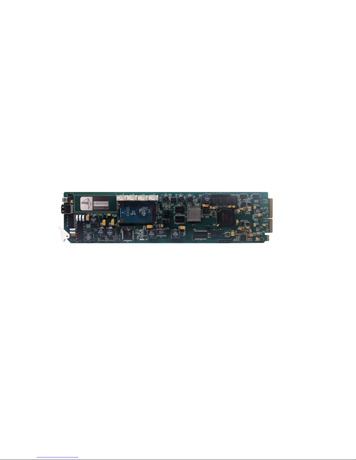
The HD1492 Encoder Card brings the functionality of EEG’s industry
standard Smart Encoder to the openGear®platform, providing closed
captioning and XDS encoding in a single modular frame card operating
on the openGear®platform. The frame card utilizes the user friendly
DashBoard software, which is available for Windows, Mac and Linux op-
erating systems and streamlines setup of the HD1492.
Like the 1RU HD492, the HD1492 streamlines and integrates the Line
21/HD-VANC encoding process into one powerful solution, supporting a
wide variety of powerful ancillary data software on-board. The HD1492
includes connection software for EEG’s iCap™ Realtime Captioning Sys-
tem, and in combination with the ComCC-1250 card can provide an un-
precedented level of reliable and redundant connectivity solutions.
3
HD1492 HD Encoder Frame Card
2 Installation
2.1 Rear Modules
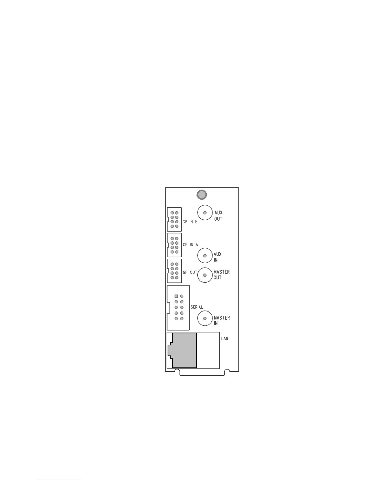
There are two back panel configurations available for the HD1492. The
single-width rear panel is shown here, followed by a guide to the con-
nectors it contains.
2.1.1 Single-Width Rear Module
4

HD1492 HD Encoder Frame Card
MASTER IN Master video input. Accepts SMPTE 259M
SD–SDI, SMPTE 292M HD–SDI, or SMPTE
424M 3G–Level-A SDI.
AUX IN Auxiliary video input. Can be used as a
source of caption data when connected to
a captioned 3G–SDI, HD–SDI, or SD–SDI
video source. Caption data from the Aux
Video In will be up-converted or down-
converted as necessary for encoding onto
the Master Video signal. If caption data is
present at both the Master Video In and the
Aux Video In, the signal with HD data will
take precedence.
MASTER OUT Program video output with relay-bypass
protection.
AUX OUT Auxiliary video output with relay-bypass
protection.
GP IN A and GP IN B Two Molex 87831-0841 connectors, each
containing 4 GPI inputs. See Appendix A for
more information regarding GPIO usage.
GP OUT Molex 87831-0841 connector containing 4
GPI outputs. See Appendix A for more in-
formation regarding GPIO usage.
SERIAL Connector for cable containing two DB–9
(RS-232) serial ports labeled P1 and P2.
Both serial ports can be used as inputs for
configuration.
LAN 1000-Base Ethernet port for connection to
LAN. After configuring your HD1492’s net-
work settings in DashBoard (see below),
you can view the Web Configuration site for
your card by navigating to its local IP ad-
dress in your web browser.
5

HD1492 HD Encoder Frame Card
2.1.2 Double-Width Rear Module
The double-width rear module provides a modem connector, in addition
to the I/O included on the single-width rear module, and takes up 4 card
slots in the openGear®frame, instead of 2.
6

HD1492 HD Encoder Frame Card
IN1 Master video input. Accepts SMPTE 259M
SD–SDI, SMPTE 292M HD–SDI, or SMPTE
424M 3G–Level-A SDI.
IN2 Auxiliary video input. Can be used as a
source of caption data when connected to a
captioned HD–SDI or SD–SDI video source.
Caption data from the Aux Video In will be
up-converted or down-converted as neces-
sary for encoding onto the Master Video
signal. If caption data is present at both the
Master Video In and the Aux Video In, the
signal with HD data will take precedence.
OUT1 Program video output with relay-bypass
protection.
OUT2 Auxiliary video output with relay-bypass
protection.
GPIN A and GPIN B Two Molex 87831-0841 connectors, each
containing 4 GPI inputs. See Appendix A for
more information regarding GPIO usage.
GP OUT Molex 87831-0841 connector containing 4
GPI outputs. See Appendix A for more in-
formation regarding GPIO usage.
RS232 Connector for cable containing two DB–9
(RS-232) serial ports labeled P1 and P2.
Both serial ports can be used as inputs for
configuration.
LAN 1000-Base Ethernet port for connection to
LAN. After configuring your HD1492’s net-
work settings in DashBoard (see below),
you can view the Web Configuration site for
your card by navigating to its local IP ad-
dress in your web browser.
Modem Standard phone jack data port. Connect to
a phone line to enable dial–up captioning.
This feature is optional on the HD1492.
7

HD1492 HD Encoder Frame Card
3 HD1492 Operation
3.1 Front Panel
The front of the HD1492 card is depicted in the following diagram:
Power LED The power LED will be green when the
card is receiving power from the frame.
USB Connectors Reserved for future use.
Video Status (AUX) This LED will be off when there is no
video present on the auxiliary input.
When HD or 3G video is present, it will
be green, and when SD video is present,
it will be orange.
Video Status (Main) This LED will be red when there is no
video present on the main input. When
HD or 3G video is present, it will be
green, and when SD video is present, it
will be orange.
3.2 DashBoard Menus
The DashBoard software is used to configure encoder settings, network-
ing, and perform additional basic configuration for the frame card. It
can be downloaded from Ross Video: https://www.rossvideo.com
Once you have successfully installed the DashBoard tool, open the pro-
gram to find information about the HD1492 and to configure your card.
8

HD1492 HD Encoder Frame Card
There are two main sections in the DashBoard interface: the Status in-
formation on the left side and the Setup menu on the right side. At the
bottom of the interface, you will find the Upload button, which can be
used to upgrade your HD1492’s DashBoard interface firmware, and the
Reboot button, which can be used to reboot your HD1492.
The upper section on the left shows the Card State and the Connection
status, each of which has an indicator light and description of the card’s
status. There is a more detailed tab labeled Status Information below
the two basic indicators that provides information about the card’s ver-
sion and its current setup configurations.
The System Status section shows what video types are present and
the current status of the Ethernet connection. Output Status displays
the mode that the encoder is operating in; the icon will be green when
the unit is in active operating mode and will be red when the Encoder
is in Relay Bypass mode. Master Input Format displays the video type
detected on the master video input, including format information for HD
video, while Auxillary Input Format indicates the video type detected on
the auxillary video input, including format information for HD video. The
Upgrade Status field displays information about whether the encoder is
9

HD1492 HD Encoder Frame Card
currently loading an upgrade.
The lower section entitled Product displays identifying information about
the hardware and software versions of the card. This section displays
the supplier, the build number, the firmware number, and the ASW ver-
sion to identify the software installed and the serial number of the card.
The setup section in the right half of the tool is broken up into mul-
tiple tabs: System, iCap, Encoding, SCTE-104, TCP/IP, and CCMatch.
Note that the SCTE-104 and CCMatch tabs will only be present if your
HD1492 has been licensed to use the respective software modules.
10

HD1492 HD Encoder Frame Card
3.2.1 System
The System tab contains network configuration and general setup fields.
MAC Address Displays the encoder’s MAC address.
Configuration Selects between static and DHCP network
settings.
IP Address Selects the IP address the unit will be as-
signed on your LAN (read-only in DHCP
mode).
Subnet Mask Selects the bit mask used; this should
match the mask used on your LAN (read-
only in DHCP mode).
Gateway Selects the address of the device that the
unit will use to communicate outside of
your LAN (read-only in DHCP mode).
Serial Port P1 Mode Selects the signaling mode used by the P1
serial port; options are RS-232, Sony-style
RS-422, and EEG-style RS-422.
Timecode Source Selects the timecode source for any appli-
cations requiring it; options are ANC VITC,
DVITC Master, and DVITC Aux.
11
HD1492 HD Encoder Frame Card
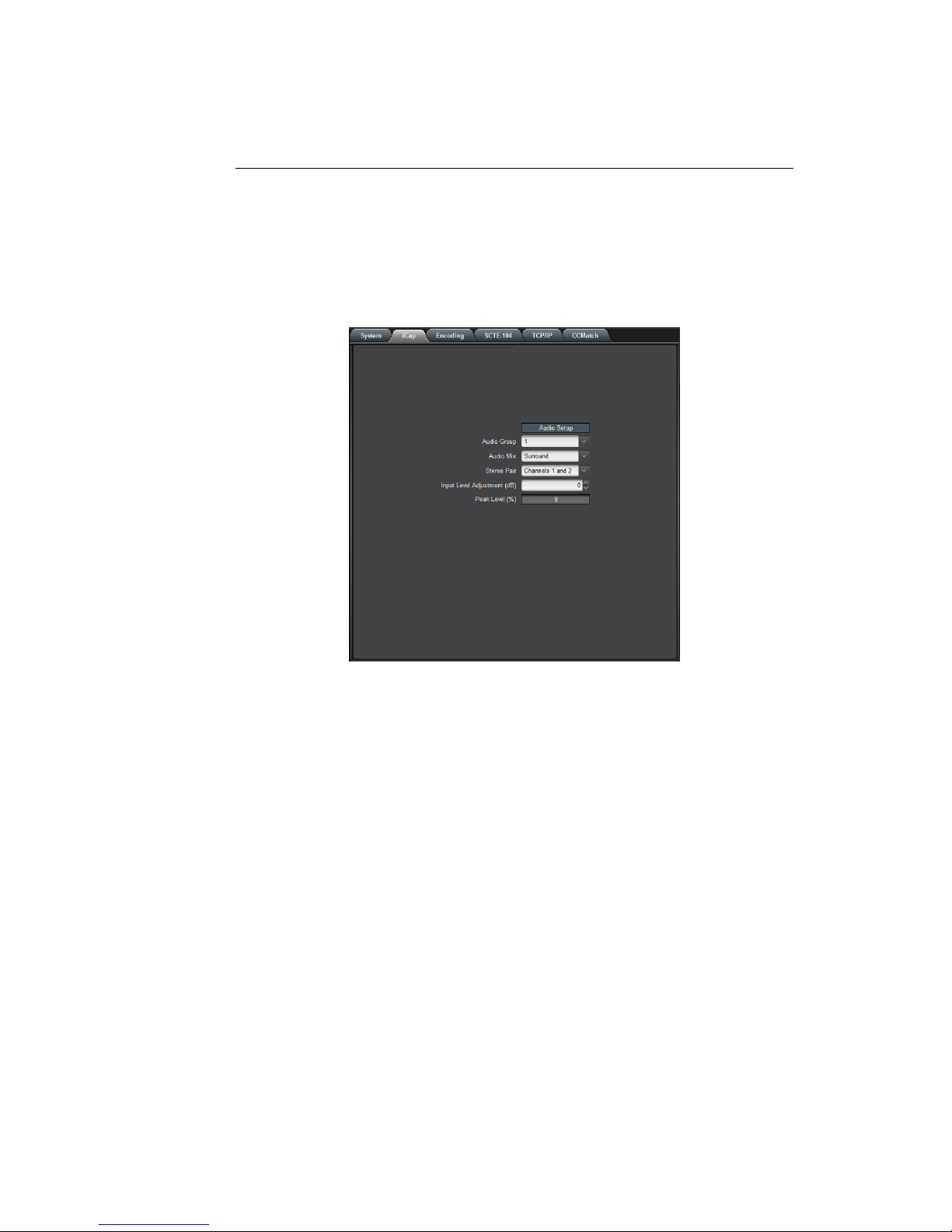
3.2.2 iCap™
The iCap™ setup menu allows configuration and monitoring of audio for
iCap™.
Audio Group Selects the SDI embedded audio channel group
that the iCap™mix is sourced from. Up to 4
channel groups can be carried on an SDI sig-
nal, though most commonly Group 1 carries the
primary audio program.
Audio Mix Selects whether the iCap™ mix is being cre-
ated from a Stereo or Surround channel group.
Choose “Stereo” to select a mix of the left and
right channels (1 & 2 or 3 & 4 within the se-
lected Audio Group, according to the Stereo
Pair setting), or “Surround” to select a mix of
the left, right, and center channels (1, 2 & 3
within the selected Audio Group).
Stereo Pair Selects whether the iCap™ stereo mix is being
created from channels 1 & 2 or channels 3 & 4
within the selected Audio Group.
12

HD1492 HD Encoder Frame Card
Input Level Adjust-
ment (dB)
Adjusts the audio input level without adjusting
the output level of your source. The built–in
digital input trim can boost or cut the audio in-
put level by as much as 12 dB.
Peak Level (%) Dynamically displays the peak signal level at
the audio input. For optimal sound quality, the
peak level should reach at least 60% across the
screen.
13

HD1492 HD Encoder Frame Card
3.2.3 Encoding
Various aspects of the operation of your encoder can be configured here.
Insertion Selects the operating mode of the en-
coder and specifies whether data is be-
ing inserted.
VANC Readahead Determines the processing delay (ex-
cluding any effects from running CC-
Match) between the input and output
of the encoder. Select "short" for one
fourth of a line of delay and "normal"
for one line of delay.
Force Upstream Regener-
ation
Manually returns the encoder to up-
stream "Regeneration" mode. This com-
mand can be used to resume passing
of upstream caption data whenever it is
being blocked by locally input caption
data. Any captioners or devices insert-
ing local data will be removed from cap-
tion mode immediately.
14

HD1492 HD Encoder Frame Card
Test Caption Mode Allows you to enable a stream of caption
text on the 608 channel selected below.
The test captions will stop if any other
port enters caption mode on the same
channel and will automatically change
the mode to Disabled.
Test Caption Channel Sets the 608 channel on which test cap-
tions will appear if they are enabled.
15

HD1492 HD Encoder Frame Card
3.2.4 SCTE-104
If your HD1492 is licensed to use SCTE-104 insertion application, the
SCTE-104 tab will be visible and will contain controls and status infor-
mation for that application.
Date/Time of Last Trigger Displays the date and time of the last
SCTE-104 insertion trigger received.
Most Recently Connected
Client
Displays the IP address and port of the
last client to connect to the card over
the LAN.
Num. Clients Currently
Connected
The number of network clients cur-
rently connected to the SCTE-104 mod-
ule will be displayed here.
Enable Module Controls whether the SCTE-104 inser-
tion application is active.
VANC Insertion Line Determines which VANC line SCTE-104
packets will be inserted on.
Allow LAN Connections If set to Yes, SCTE-104 insertion can
be triggered via LAN connection on the
port specified below.
16

HD1492 HD Encoder Frame Card
LAN Port If the Allow LAN Connections setting
is turned on, this field determines the
port on which LAN connections will be
accepted.
Insert Immediately If set to Yes, a SCTE-104 packet will be
inserted into VANC immediately when
the application receives a LAN trigger.
17
HD1492 HD Encoder Frame Card
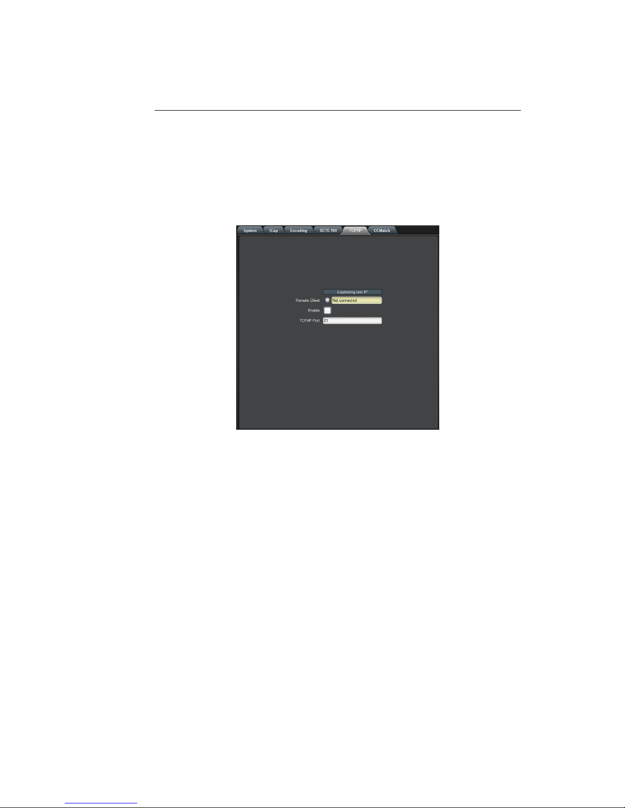
3.2.5 TCP/IP
This tab allows you to configure an optional TCP/IP connection into your
encoder, which provides an additional means of captioning, data entry,
and monitoring via Smart Encoder commands.
Connection Status When a connection into the specified
TCP/IP port is active, this field will display
Connected, with a green icon.
Enable Must be set to Enabled for connections to
be accepted on the specified TCP/IP port.
TCP/IP Port This is the port on which remote connec-
tions to the encoder will be allowed, if you
have enabled this feature; you can only
change this value while the port is disabled.
18
HD1492 HD Encoder Frame Card
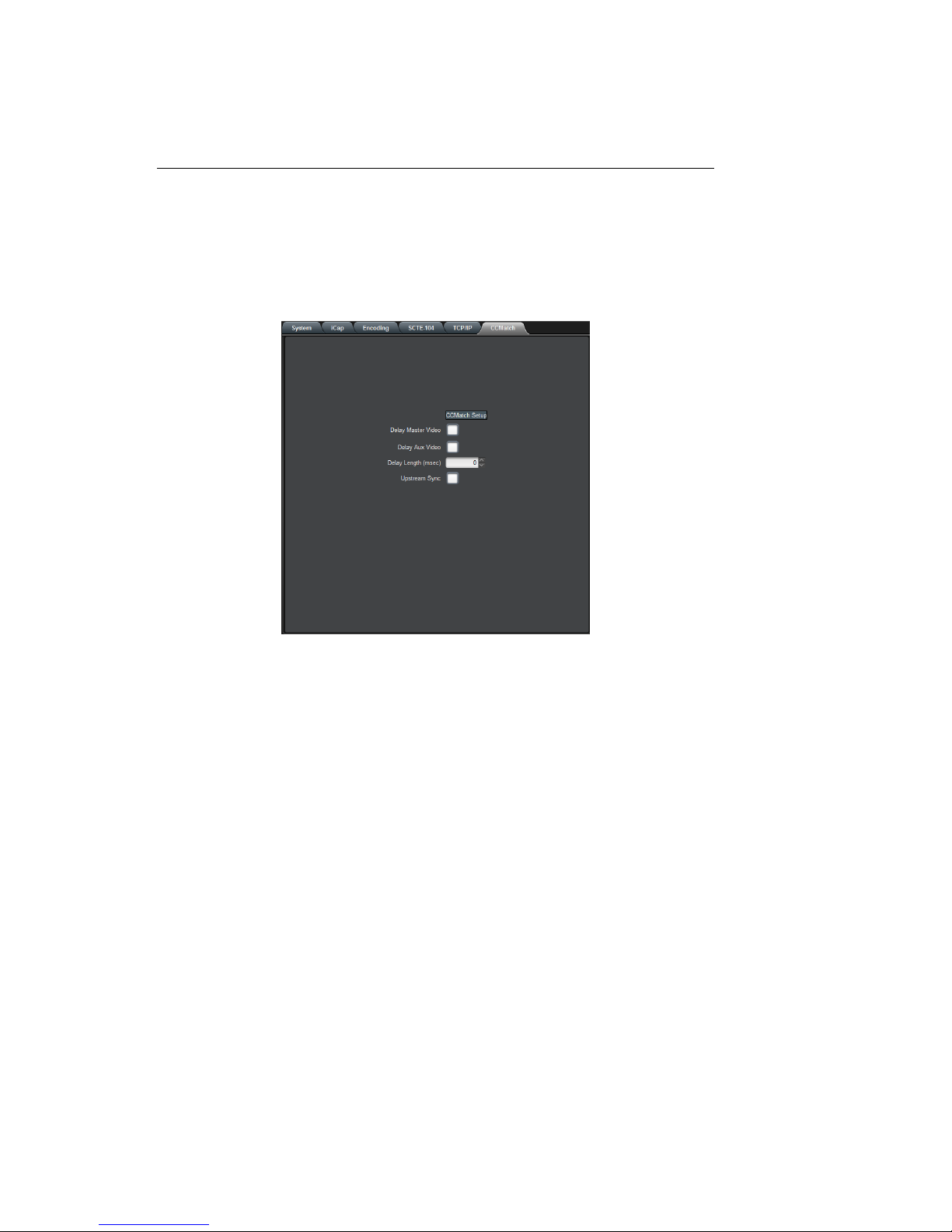
3.2.6 CCMatch
If your HD1492 is licensed to use CCMatch application, the CCMatch
tab will be visible and will contain controls for that application.
Delay Master Video Checking this box will delay the master
video channel by the amount specified in
the Delay Length field.
Delay Aux Video Checking this box will delay the auxiliary
video channel by the amount specified in
the Delay Length field.
Delay Length (msec) The delay, in milliseconds, for any video
channels checked above. This should
match the anticipated latency between your
audio and your captions, before adjust-
ment.
Upstream Sync Checking this box will cause upstream cap-
tions to be re-timed, in order to better syn-
chronize them with your program audio.
19
Table of contents
Other EEG Media Converter manuals


