manuals.online logo
Brands
  1. Home
  2. •
  3. Brands
  4. •
  5. Cerberus
  6. •
  7. Smoke Alarm
  8. •
  9. Cerberus inteLINK DI-4A User manual

Cerberus inteLINK DI-4A User manual

Introduction
The Cerberus Pyrotronics Model DI-4A smoke detector
with adjustable sensitivity operates on the ionization
principle. It is designed to respond to the first traces of fire
in the form of visible smoke or invisible products of
combustion. Heat or flame is not required to activate the
detector. The Model DI-4A detector has been developed
for protection of a wide range of commercial, industrial,
institutional, and residential occupancies.
Technical Description
The DI-4A detector is a plug-in, dual chamber ionization
detector with adjustable sensitivity and contains two
ionization chambers together with a highly sensitive
semiconductor amplifier-switching circuit. One chamber
detects the presence of combustion products. The
second chamber serves as a reference, to stabilize the
detector’s sensitivity for changes in environmental tem-
perature, humidity, and pressure. The detector assembly
locks in upon alarm; therefore it must be reset at the
control panel.
The DI-4A can be manually adjusted to two different
sensitivity settings; Low and High. This is easily done by
moving the sensitivity indicator, located on the underside
of the detector housing, with a small pointed instrument
such as a ball point pen.
The detector operates from a 20 VDC source, provided by
the Cerberus Pyrotronics control panel. The detector
requires a very small standby current (less than 110µA),
which permits the use of a 2-wire detector circuit of #18
AWG wire, reducing system installation costs. In alarm,
the detector will draw approximately 175mA (with remote).
The DI-4A detector is Underwriters Laboratories Inc. listed
for ordinary indoor applications.
Base assemblies for either flush or surface mounting, all
with screw type terminals, are available for use with the DI-
4A detector as follows:
DB-4TS Surface Base with Integral Alarm Lamp and
Terminal Connection for Remote Relay or
Remote Alarm Lamp
DB-4TF Flush Base with Integral Alarm Lamp and
Terminal Connection for Remote Alarm
Lamp
A remote indicator lamp, Model RL-30 or RL-40 may be
connected when the detector is concealed from view or a
remote relay, Model RR-2, may be connected to the DI-4A
where a detector-controlled function is required at or near
the detector. The Model RR-2 relay has one set of double-
pole, double throw contacts rated at 120 VAC, 2 Amp.
resistive.
6113
CATALOG NUMBER
DI-4A
Ionization Smoke Detector
ENGINEER AND ARCHITECT SPECIFICATIONS
lFlush or Surface Mounting
lCompact
lAdjustable Sensitivity
lScrew-type Terminals
lVersatile
lNew “Free Flow” POC Path
lRugged
lAlarm Light
lSimple Twist/Lock Assembly
lSolid State Circuitry
lSuperior Air Velocity Characteristics
lListed, ULC Listed, FM, CSFM, NYMEA and
City of Chicago Approved
firealarmresources.com
When the RR-2 is used and the control function is critical,
no more than one DI-4A should be installed in a particular
circuit or zone, and no other initiating devices should be
installed in that same circuit or zone. An exception to this
rule would be an application where a number of RR-2
relays were used, each of which was connected to the
same critical control function.
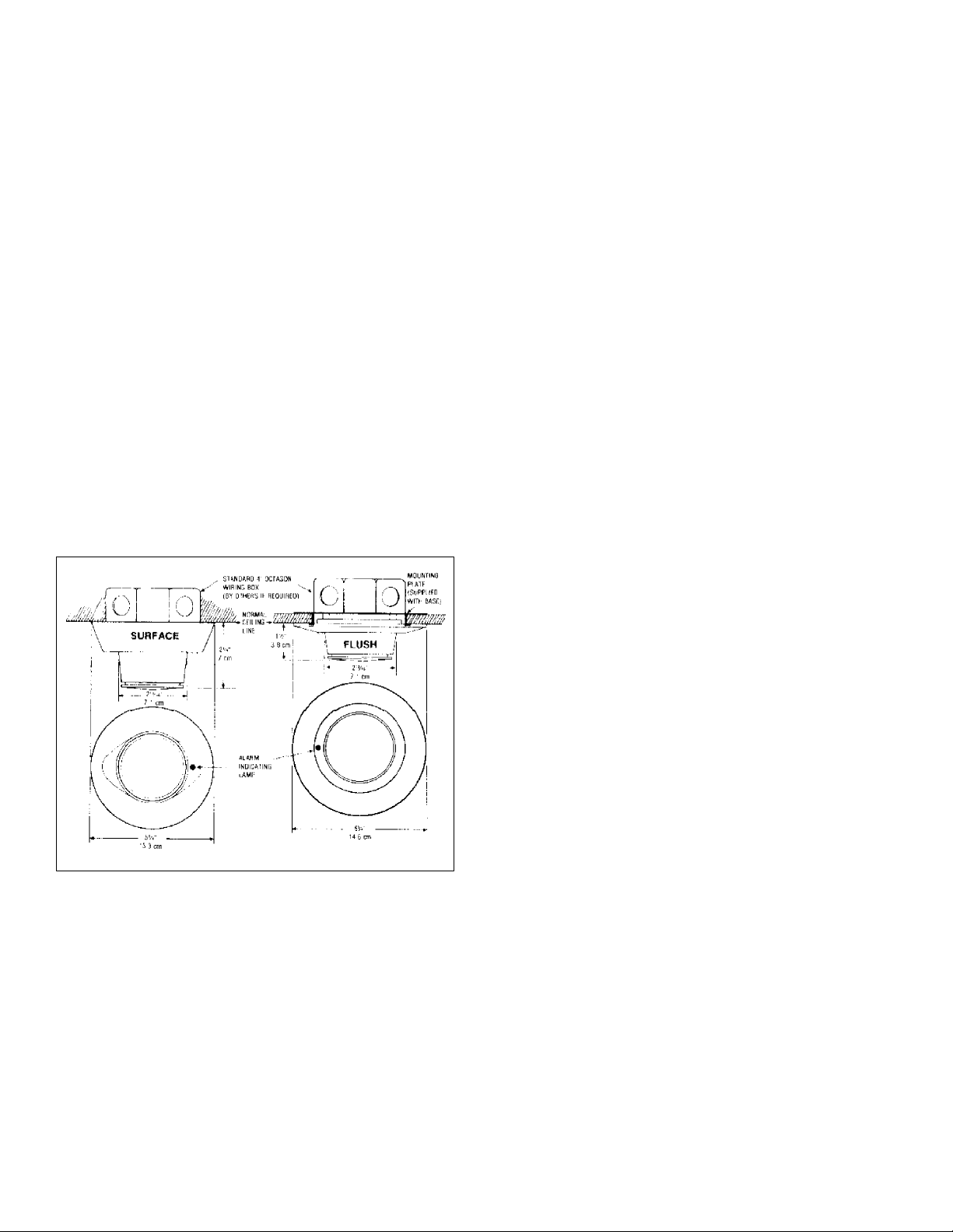
Mounting Data
The DI-4A detector utilizes either a flush or surface mount-
ing base assembly. Each base may be attached to a
standard 4" octagonal electrical box with an adapter
(included) when conduit is used, or may be used without
box when local building codes permit. The DB-4TS base
contains provision for an optional field installed locking
mechanism to prevent unauthorized removal of the
detector head. A flush locking base, Model DB-4TFL, is
also available.
The detector shell and base are fabricated of rugged
polycarbonate material eliminating any corrosion prob-
lems. They are off-white in color and attractively styled to
be unobtrusive and to match most interiors.
By using the Cerberus Pyrotronics sensitivity tester, Model
MG-7/9 the detector can be easily checked for proper
operation.
Application Data
No more than thirty (30) detectors of any type or combina-
tion (other than thermals or manual stations) may be used
on any one Cerberus Pyrotronics detector circuit.
This detector is applicable to the 30-foot center spacing
(900 sq. ft.) as referred to in the National Fire Protection
Association Standard 72. This, however, is based on ideal
conditions, namely, smooth ceiling, no air movement, and
no physical obstructions between the fire source and the
detector. This spacing should be used as a guide or
starting point in detector installation layout. Do not mount
detectors in areas close to ventilating or air conditioning
outlets. Exposed joists or beamed ceilings may also affect
safe spacing limitations for detectors. It is mandatory that
engineering judgment be applied regarding detector
location and spacing.
Engineer and Architect Specifications
The fire detector shall be a Cerberus Pyrotronics Model DI-
4A with adjustable sensitivity. It shall operate on the
ionization principle, activated by the presence of combus-
tion products, and shall be listed by Underwriters Labora-
tories Inc. The detector shall be a plug-in, twist/lock unit
which may be installed in or removed from its base with
one hand.
The detector shall contain two ionization chambers,
amplifier-switching circuit and solid state indicator lamp.
One chamber shall be for fire detection and the second
chamber shall function as a reference, to stabilize the
detector for changes in environmental temperature,
humidity, and pressure. The unit shall contain no operat-
ing moving parts.
The amplifier-switching circuit in the detector shall be
entirely solid state, and shall operate with a detector line
voltage of 20 VDC.
The unit shall be capable of being manually adjusted for
low or high sensitivity. The resulting sensitivity setting shall
be visible through an indicator slot located on the detector
housing. No special tools shall be required to change the
sensitivity setting.
The base assembly into which the detector is installed
shall be of the twist/lock type with screw type terminals,
and shall be a Cerberus Pyrotronics Model DB-4 (Insert TS
or TF). Pigtails or in-line connectors shall not be permitted.
The base shall include a lamp to indicate alarm of the
detector.
firealarmresources.com
It is possible to connect either a remote lamp, Model RL-
30, RL-40 or a remote relay, Model RR-2, to the base
assembly. The relay shall contain a set of DPDT contacts,
rated at 120V, 60Hz, 2 amp. resistive, for the control of
external devices.
A security base lock shall be installed in those areas where
tamper resistant installation is required.
If maintenance is required, the unplugged detector shall
be capable of normal handling without causing damage to
components, such as field effect transistors.
The detector, or group of detectors, shall require a two-wire
circuit of #18 AWG thermoplastic fixture wire enclosed in
conduit, or #18 AWG limited energy shielded cable without
conduit, if permitted by local building codes.
Ordering Information
Typical Wiring
Model DescriptionShippingWt.
DI-4ADetector,Ionization,withAdjustableSensitivity1 lb. (.45 kg.)
DB-4TSBaseAssemblywithAlarmLampandTerminal
forRemoteRelayorLamp,SurfaceMtg.
(Includesadapterfor4"octagonalbox)1 lb. (.45 kg.)
DB-4TFBaseAssemblywithAlarmLampandTerminal
forRemoteRelayorLamp,FlushMtg.
(Includesadapterfor4"octagonalbox)1 lb. (.45 kg.)
545-080117 BaseLockingKitforDB-4TS .5lb.(.22 kg.)
DB-4CVRDustCoversforDB-4TS
DB-4TFLFlushBasewithLock1 lb. (.45 kg.)
RR-2RemoteRelay1 lb. (.45 kg.)
RL-30/RL-40 RemoteAlarmLamps1 lb. (.45 kg.)
465-514391 Cable,LimitedEnergy,Shielded(foruse
wherebuildingcodespermitdetectorwiring
withoutconduit),2-wire(1000'roll)50 lb.(22.5kg.)
firealarmresources.com

This manual suits for next models

1

Popular Smoke Alarm manuals by other brands

ADEMCO PY2700TEM Installation and maintenance instructions

ADEMCO

ADEMCO PY2700TEM Installation and maintenance instructions

xeltys TANA X5 user manual

xeltys

xeltys TANA X5 user manual

Haibrain PGSD834 user manual

Haibrain

Haibrain PGSD834 user manual

Fire-Lite AFM-16ATX user manual

Fire-Lite

Fire-Lite AFM-16ATX user manual

AU Tool SDT205 user manual

AU Tool

AU Tool SDT205 user manual

ESMI EB-6500R Installation and maintenance instructions

ESMI

ESMI EB-6500R Installation and maintenance instructions

AMC 800 Series manual

AMC

AMC 800 Series manual

Kidde P3010CU user manual

Kidde

Kidde P3010CU user manual

System Sensor 6500S Installation and maintenance instructions

System Sensor

System Sensor 6500S Installation and maintenance instructions

Bosch Fireray3000 Specifications

Bosch

Bosch Fireray3000 Specifications

Smanos SMK-500 user manual

Smanos

Smanos SMK-500 user manual

GST D Series Application Bulletin

GST

GST D Series Application Bulletin

Visonic SMD-426 installation instructions

Visonic

Visonic SMD-426 installation instructions

Marquant 442055 operating instructions

Marquant

Marquant 442055 operating instructions

Kidde PE910UK user guide

Kidde

Kidde PE910UK user guide

Kidde i12020ACA manual

Kidde

Kidde i12020ACA manual

ELRO FS1510M instruction manual

ELRO

ELRO FS1510M instruction manual

ELRO FS111011P quick start guide

ELRO

ELRO FS111011P quick start guide

manuals.online logo
manuals.online logoBrands
  • About & Mission
  • Contact us
  • Privacy Policy
  • Terms and Conditions

Copyright 2025 Manuals.Online. All Rights Reserved.