Cerlic FLX User manual

2009-09-14 C70B5EN10
FLX
FLX
Level / Flow
Sensor

- 2 -
FLX
TABLE OF CONTENTS
1. Introduction................................................................................................ 3
2. A few words about this manual ................................................................ 3
3. Design......................................................................................................... 3
4. Measuring principle................................................................................... 3
5. Unpacking the Sensor............................................................................... 4
6. Mounting..................................................................................................... 5
Mounting a Sensor in a Flume....................................................................................................5
Mounting a Sensor in a Weir......................................................................................................6
Electrical Connection .................................................................................................................6
Starting Up .................................................................................................................................7
7. Removing the sensor................................................................................. 7
8. Maintenance ............................................................................................... 8
9. Sensor display ........................................................................................... 8
10. Menu for FLX sensor ................................................................................. 9
Level measurement...................................................................................................................11
Parshall flume...........................................................................................................................11
Thompson Weir........................................................................................................................12
Rectangular Weir......................................................................................................................12
Rectangular Weir with End Contractions.................................................................................13
Palmer-Bowlus Flume..............................................................................................................13
Cipoletti Weir...........................................................................................................................14
Sutros Weir...............................................................................................................................14
Venturi Flume with Rectangular Throat...................................................................................15
Throat.......................................................................................................................................15
Venturi Flume with U-shaped Throat.......................................................................................16
11. Calibration................................................................................................ 17
Zero calibration ........................................................................................................................17
Level calibration.......................................................................................................................17
12. Scaling...................................................................................................... 18
13. Overflow functionality ............................................................................. 18
Automatic Adjustment .............................................................................................................18
Resetting the overflow counter.................................................................................................19
14. Totalizer.................................................................................................... 19
15. Technical data FLX .................................................................................. 20
Dimensions..................................................................................................... 22
Appendix 1, Optional slide rail...................................................................... 23
Appendix 2, Support information.................................................................. 23
Appendix 2, Support information.................................................................. 24
Appendix 3, Setup information ..................................................................... 25

- 3 -
FLX
1. Introduction
FLX is used to measure level and flow in open channels in water treatment plants and
applications.
2. A few words about this manual
This manual details installation procedures and operational features of the Flow sensors.
Menu navigation and technical data for the BB2 control box can be found in the BB2
service manual.
3. Design
The FLX sensor is manufactured in SIS2343 (316SS) stainless steel and PVC. The
sensor is mounted using PVC clamps. An adjustable stainless steel slide rail mounting
assembly is available as an option.
The sensor has a fixed, shielded 5 m (16’) ventilated cable connecting the sensor to a
ventilated junction box. A second 10 m (33’) cable fixed to the junction box connects
junction box and the BB2 control box.
4. Measuring principle
The FLX uses a pressure sensor to measure flow as a function of the level of the liquid
in open channels. Different types of standardized weirs or flumes are used to achieve
measurable rates of flow. The characteristics of these weirs and flumes are documented
in a number of publications. Since this manual primarily describes the FLX, we will not
provide in-depth descriptions of weirs or flumes, but refer to the sources listed below.
Most flumes and weirs can be bought directly from a supplier as a prefabricated product
(assembled or partially assembled). It is also possible to construct flumes or weirs
yourself. If you do, it is very important to follow the prescribed recommendations.
In order to achieve accuracy in measuring flows in open channels the correct installation
of the flumes and weirs is crucial. Always follow the installation instructions. An
improper installation may easily lead to a measuring error of 25% or more.
The central unit BB2 has built-in mathematical formulas for most flumes and weirs.
When starting up, select the correct flume/weir and enter the specific parameters for that
flume/weir. This primarily concerns actual dimensions.
All settings are made in the BB2 by using self-instructing menus controlled by just three
keys. Metric or US units can be chosen. The output signals are frozen when the menus
are open in order to avoid problems, e.g during calibration. BB2 provides two 4-20mA

- 4 -
FLX
outputs and two relay outputs for an external totalizer and for the built-in batcher, for
controlling sampling.
The flow is presented continuously in a display window. By simultaneously pressing
two keys the current water level as well as the internal totalizer value are displayed. The
temperature is measured by the transmitter to be used for temperature compensation of
the measured value. It can be read in the BB2 box, and like the level be used as
secondary value when a transmitter is configured to use both analog outputs of the BB2.
The temperature is not a precision measurement, but shall be seen as an indication
In-depth descriptions of weirs or flumes:
•
ISO Standards Handbook 16, 1983.
•Water Measurement Manual - US Department of the Interior, Bureau of
Reclamation, Denver, Colorado, USA, 1974.
•Parshall, R.L: Measuring water in irrigation channels with parshall flumes and
small weirs. Soil conservation circular no 843, US Department of Agriculture,
May 1950.
5. Unpacking the Sensor
The unit has been tested and approved before delivery from the supplier. Please check
to confirm that no visible damages occurred during shipment.
Damages
If damages occurred during shipment, immediately contact UPS or other truck line as
well as your Cerlic representative. The shipment can be returned only after contact has
been made with Cerlic.
Packaging
The original packaging is designed to protect the equipment and should be used for
storage or if the goods must be returned.
Content
Please check that the content corresponds to your order and packing list.
Every shipment should include:
•Sensor with 5 m (16’) ventilated cable, a junction box and 10 m (33’) signal cable.
Optional parts for FLX: P/N
•Slide rail for 28 mm Sensors 11205264
•10m (33 ft.) extension cable with plug-in connectors. 20805510
•Y-Splitter for two sensors to one BB2 control box 21505534
•Connection box for two sensors to one BB2 control box 1505748
with 1m (3 ft.) cable to connect to BB2
•Connection box for four sensors to one BB2 control box 11505785
with 1m (3 ft.) cable to connect to BB2

- 5 -
FLX
6. Mounting
The sensor must be mounted perpendicular to the horizontal plane to measure
accurately. It must be firmly mounted. From a maintenance and service point of view, it
is advisable to mount it in such a manner that removal for inspection and cleaning is
easy. It is important that the sensor, once it has been removed, is re-positioned at the
right height. An adjustable slide rail mounting is available as an option. In strong
current, hydrodynamic effects may influence the measurement; contact Cerlic service
for advice on current protection if problems occur.
CAUTION!
The sensor is fragile!!
Never drop a sensor on a hard surface!!
Mounting a Sensor in a Flume
In flumes (Parshall/Venturi/Palmer-Bowlus), the sensor should be mounted in a
measuring well. This is done to avoid sensor interference with the flow profile in the
flume. Prefabricated flumes often have measuring wells as a standard feature, but this
should be verified. Existing concrete flumes without a measuring well can almost
always be retrofitted with one. One method would be to use a diamond-tipped hole saw
to drill a hole in the side of the flume near the flume's edge, so that an opening is
created between the drilled hole and the flume. Whenever possible the measuring well
should be 50 mm (2") deeper than the highest part of the flume's bottom. (Refer to h1 on
the illustration below.)
Sensor placement in a Parshall fume

- 6 -
FLX
Mounting a Sensor in a Weir
In a weir, the sensor should be placed at 4 times the maximum measuring height
upstream from the overflow edge. If possible, measuring in a measuring well is
preferably. However, this is not strictly necessary since the sensor ends up so far from
the overflow that its interference with the flow profile is negligible.
4h max
h
Sensor placement when using a rectangular weir
Electrical Connection
Connect the sensor to the BB2 central unit using the attached cable. The cable from the
sensor to the junction box is ventilated to enable the sensor to compensate for changes
in the atmospheric pressure. The junction box has a small hole to let the air in and
out, make sure to mount the junction box so this hole is pointing downwards. If
needed, the signal cable from the junction box to the BB2 can be extended using
extension cables. Several sensors can be connected to one BB2 using Y-splitter or
junction box. See “Technical description” for details.
This side up
Small hole

- 7 -
FLX
Starting Up
Fill a bucket with approximately 25cm (10") water.
Connect the sensor to the BB2, let BB2 find the sensor, and select the slot to be used.
Select the sensor in the Measure display using or .
Press and ENTER at the same time to get the FLX info display.
If the sensor is held vertically in the air the level shall read zero (or close to zero). The
FLX is pre-set at the factory, but sometimes the zero point still needs adjustment. (Refer
“Adjusting the zero point”). NOTE, if an offset is entered in the sensors setting menu,
the level shows the value of the offset instead of zero.
Carefully lower the sensor into the bucket until the sensor rests on the bottom of the
bucket. Use the ruler and measure the water level. The level shall be 12 mm (1/2”) more
than the meter shows. The difference is the distance from the bottom of the sensor to the
top of the holes where the pressure is measured. NOTE! If an offset is entered in the
sensors setting menu, the meter adds the value of the offset to the measured level. That
is, if an offset of 12 mm (1/2”) is entered the sensor shows the total water level in the
bucket.
If both the zero and the level is OK, the sensor is ready for use.
If they are not, please refer to the service and maintenance part of the manual.
7. Removing the sensor
The sensor is removed in the following steps:
•Disconnect the sensor cable from the BB2.
•Dismount the sensor.
•Clean the sensor with a brush or clean cloth. Do not use a wire brush!
•Mount the protective cap (or a small plastic bag) on the sensor cable connector.
If the sensor needs cleaning, use warm water and a bottle brush to clean the measure
cell; do not use a metallic brush or sharp tools.
The sensor housing may not be opend except by Cerlic service personel. Opening the
sensor housing will void all warrenty.

- 8 -
FLX
8. Maintenance
All sensors age, which eventually leads to inaccurate measurements. Check the sensor's
zero point about once every six months by lifting the sensor into the air and observing
the level the FLX registers. The level is shown in the sensors info display (opened by
simultaneously pressing and ENTER). If the sensor is held vertically in air, the
sensor should give the same level as the offset level in the menu.
If it does not, you should calibrate the zero point. (See section “Calibration”)
Incorrect Measurement
If the sensor gives incorrect measurements even though the zero point has been
calibrated, the sensor may need a level calibration. A description of how to do this can
be found in the section "Calibration"
If the sensor is mounted in a strong current, an under pressure may form around the
sensor. This will lead to a faulty measurement. The easiest way to avoid this type of
problem is to mount a tube around the sensor in order to form a calm measuring well.
The tube may rest on the bottom of the flume, but there must be some holes below the
surface of the fluid in order to get the same level in the tube as in the flume.
9. Sensor display
By simultaneously pressing and ENTER you alter between BB2 main menu and the
sensor information display for the selected sensor. On the sensor information page FLX
shows in addition to the measured value, the current level, the totalizer, and the number
of overflows.

- 9 -
FLX
10. Menu for FLX sensor
Use or to select the sensor in the main display. The menu for the selected sensor
is accessed by pressing ENTER for five seconds. If the selected sensor is not active (the
text No transmitter is shown) a warning is displayed that asks you to make another
choice in order to show the sensor menu.
Settings
Tag Name of the sensor (10 characters) shown in the main display.
Flume "Parshall", "Thompson", "Rect. wier", "RWC", "P & B",
"Cipoletti", "Sutro", "Venturi" or "Venturi U". One or more
parameter questions will follow the choice of flume. The Flume
selection is ignored when unit “mm” or “Inch” is used below.
# Flumes 0-255, the number of parallel flumes.
I-Time Integration time or dampening - can be set up to 999 seconds
Unit ”Inch”, ”MGD”, ”GPH” or ”GPS” if US units are used,
”mm”, ”m3/h”, ”m3/s” or ”l/s” if metric units are used.
Preset 0-9999.9, volume, in kilo Gallon if US units are used, or m3 if
metric units are used, to give a pulse on the pulse relay.
Pulse Relay ”-” ”#1”, or ”#2”. Check that the relay is not being used for
cleaning
Reset Sum ”Yes”, or ”No”, reset the totalizer.
Overflow ”Yes”, or ”No”, count overflows.
Auto Adj. ”Yes”, or ”No”, Automatic zero calibration adjustment when
overflow is selected above.
Reset Overfl. ”Yes”, or ”No”, reset the overflow counter.
Analog ”None” , ”Out1”, ”Out2”, ”Out3”, ”Out4”, ”Out1+2”, or ”Out3+4”.
Pick which analog output(s) to be used with sensor
Second ”Level”, “Temp” or ”=Prim”. If two channels are chosen above,
the first will always give the primary value according to the
sensors selected scale. The second will either give the level
scaled 0-1000 mm, the temperature scaled 0-100°C, or the
same signal as the first. The temperature is additional
information, not a precision measurement.
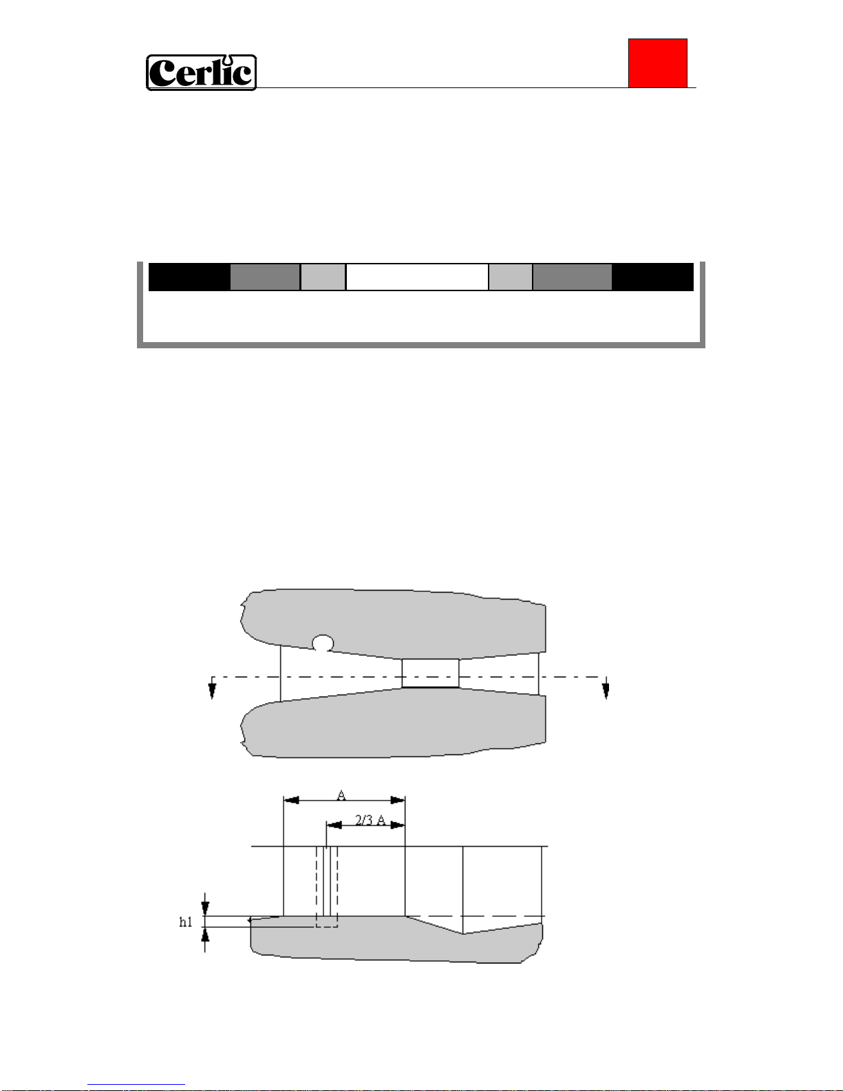
Calibrate
At Zero Set the offset (below) so the meter show zero at current level
Offset +/- 0-99.9” if US units are used, +/- 0-999 mm if metric units are
used. Defines how far above (positive value) or below (negative
value) the sensor is placed vertically from the overflow edge. 0
means that the sensor is level with the overflow edge. When the
automatic zero point adjustment of the overflow function is
activated, the offset value is automatically set to 0.
Calibrate “No“, “Zero”, or “Level”. Refer to calibration instructions for
details.
Cal. Level 0-99.9” if US units are used, 0-999 mm if metric units are used.
Level when the level calibration was done. Forced value to
adjust span of sensor.
0-Cal. Date of last zero calibration.

- 10 -
FLX
Scale / Alarm
Max Measured value corresponding to 100%, equal to 20 mA output
signal (or 4 mA if 20-4 mA is used).
Min Measured value corresponding to 0%, equal to 4 mA output
signal (or 20 mA if 20-4 mA is used).
Hi Alarm Level that activates an alarm when exceeded, 0 = not in use.
Low Alarm Level that activates an alarm when underpassed, 0 = not in use.
Alarm Relay ”-” ”#1”, ”#2”, or ”#1 and #2”. Check that the relay is not being
used for cleaning
System
Type Type of sensor, read only
Serial Serial number of the sensor, read only
SoftW Software version of the sensor, read only
Temp Sensor temperature, read only
MaxTemp The highest temperature the sensor has been exposed to, read only
Info Press “ENTER” to go to “info” read only menu. This menu is for
Cerlic internal use.
Sa 0 Raw value for the zero level
Sa 1 Raw value for the calibrated level
Level 1 The calibrated level
Ch1 Current raw value
Raw level Level without any compensation
Reading Current measure value
Samp/s Number of messages per second from the sensor.
Service Not accessible for users.

- 11 -
FLX
Level measurement
FLX can be configured for level measurement by selecting the unit ”mm”or”inch” in
the sensors settings menu. Type of flume, flume parameters and number of flumes
selected are ignored. Preset, pulse relay and totalizer does not work for level
measurement.
Parshall flume
When you select a Parshall flume, you must specify the following parameters:
Size 1,2,3,6,9,12,18,24,36,
48,60,72,84,96 "
The size of the Parshall flume in inches (see
picture above)

- 12 -
FLX
Thompson Weir
When you select a Thompson weir, you must specify the following parameters:
ANGLE
Angle 20.0 - 150.0 ° The weir's α-angle (see the illustration
above)
Rectangular Weir
When you select a Rectangular weir, you must specify the following parameters:
WI i
SILL
Sill 50 - 8000mm
(5.0 - 800.0 ")
The sill height of the weir (see the illustration
above)
WI i 50 - 32 000mm
(5.0 - 3200.0 ")
The width of the weir (see the illustration
above)

- 13 -
FLX
Rectangular Weir with End Contractions
When you select a Rectangular weir with end contractions, you must specify the
following parameters:
SILL
WI o
WI i
Sill 50 - 8000mm
(5.0 - 800.0 ")
The sill height of the weir (see the illustration
above)
WI i 50 - 32 000mm
(5.0 - 3200.0 ")
The inner width of the weir (see the
illustration above)
WI o 50 - 32 000mm
(5.0 - 3200.0 ")
The outer width of the weir (see the
illustration above)
Palmer-Bowlus Flume
When you select a Palmer-Bowlus flume, you must specify the following parameters:
Size 1 - 22 " The size of the Palmer-Bowlus flume in inches
(see the illustration above)

- 14 -
FLX
Cipoletti Weir
When you select a Cipoletti weir, you must specify the following parameters:
WI i
WI i 50 - 32 000mm
(5.0 - 3200.0 ")
The inner width of the weir (see the
illustration above).
Sutros Weir
When you select a Sutros weir, you must specify the following parameters:
WI i
Re h
Re h 0 - 4000mm
(0.0 - 400.0 ")
The sill height of the weir (see the illustration
above).
WI i 50 - 32 000mm
(5.0 - 3200.0 ")
The width of the weir (see the illustration
above).

- 15 -
FLX
Venturi Flume with Rectangular Throat
When you select a Venturi flume with rectangular throat, you must specify the
following parameters:
Sill 0 - 4000mm
(0 - 400.0 ")
Sill height of the flume (see the illustration
above).
WI i
50 - 32 000mm
(5.0 - 3200.0 ")
The throat width of the flume (see the
illustration above).
WI o
50 - 32 000mm
(5.0 - 3200.0 ")
The outer width of the flume (see the
illustration above).
Throat 25 - 3000mm
(2.5 - 300.0 ")
The length of the throat (see the illustration
above).

- 16 -
FLX
Venturi Flume with U-shaped Throat
When you select a Venturi flume with U-shaped throat, you must specify the following
parameters:
Sill 0 - 4000mm
(0 - 400.0 ")
Sill height of the flume (see the illustration
above).
WI i
50 - 32 000mm
(5.0 - 3200.0 ")
The throat width of the flume (see the
illustration above).
WI o
50 - 32 000mm
(5.0 - 3200.0 ")
The outer width of the flume (see the
illustration above).
Throat 25 - 3000mm
(2.5 - 300.0 ")
The length of the throat (see the illustration
above).

- 17 -
FLX
11. Calibration
The sensor is shipped pre-calibrated. The sensor will drift with time. Calibrations shall
be done regularly following a maintenance schedule. Once every six months is
recommended. Always leave the sensor in the measuring media with the power on for
approximately 30 minutes before you begin calibrating. This allows the sensor to
stabilize.
Zero calibration
The FLX has a zero point calibration function, which is based on lifting the sensor into
the air (zero pressure) and pressing a key. The BB2 registers the signal from the sensor
and bases all subsequent measuring on that signal level.
Follow these steps to calibrate the zero point:
•Enter the sensor menu. The output signal is frozen while the menus are open.
•Chose the sub menu "Calibrate".
•Chose " Calibrate ", then "Zero” and press ENTER.
•Place the sensor vertically, then press ENTER to start the sampling.
•A textbox will pop up saying "Standing by for stable signal ". When the textbox
disappears, the calibration is done.
•Exit the menu.
•Date of last zero calibration is shown at the bottom of screen “0-Cal”.
Do a zero calibration two times a year in order to maintain good accuracy.
Level calibration
After a zero calibration, it is easy to check the accuracy of the sensor. Fill a bucket with
approximately 25cm (10") water. Carefully lower the sensor into the bucket until the
sensor rests on the bottom of the bucket. Use a ruler and measure the water level. The
level will be 12 mm (1/2”) more than the meter shows due to black protective cap on
end of sensor. NOTE! If an offset is entered in the sensors setting menu, the meter adds
the value of the offset to the measured level. If the instrument shows a level different
from the ruler then - a level calibration must be done.
Follow these steps to calibrate a level:
•Enter the sensor menu. The output signal is frozen while the menus are open.
•Chose the sub menu "Calibrate".
•Chose " Calibrate ", then ARROW UP to get"Level” and press ENTER.
•Carefully lower the sensor into the bucket, let the sensor rest on the bottom of the
bucket, and hold it vertically, then press ENTER to start the sampling.
•A textbox will pop up saying "Standing by for stable signal ". When the textbox
disappears, the calibration is done.
•Measure the water level in the bucket with a ruler.

- 18 -
FLX
•Subtract 12 mm (0,5”) from the measured water level in the bucket and go to “Cal
Level” in the Calibration menu and enter this value. (Example; water level in the
bucket is 20.625”. Subtract 0,5” = 20.125”. Enter this value in “Cal level”.)
•Exit the menu.
•In the display mode of BB2, press ARROW DOWN + ENTER to get to the FLX
information window.
•Check that the level reading of the FLX corresponds to the water level in the bucket
as per above.
12. Scaling
The “Scale / Alarm” menu allows the user to set the high and low boundaries for a 4-
20mA output signal. In addition, this menu allows the user to set high and low alarms
values that can be used to notify when the measurement has reached critical points.
Max sets the 20 mA point output
Min sets the 4 mA point output (may be a negative value)
Hi-Alarm sets the High Alarm set point
Low-Alarm sets the Low Alarm set point
13. Overflow functionality
When FLX is used to measure overflows, the number of overflows can be counted. The
sensor must be leveled with the edge of the overflow threshold. By doing so, the
automatic zero adjustment can be used. The positioning and mounting of the sensor
shall with this exception be done in the same way as for normal flow measurement.
To make sure that the FLX registers overflows you can lift the sensor up and lower it
into a bucket of water (200mm [7.8"]). Leave the sensor in the bucket for 1 minute, then
check that the sensor information display in BB2 has registered an overflow. Make sure
the level has been zero at least an hour prior to the overflow measure.
Automatic Adjustment
When registering overflows you can choose between calibrating the zero point
manually, or selecting automatic adjustment of the zero point. We recommend that you
use automatic adjustment of the zero point if that is possible. The automatic adjustment
function is only available if you have activated the overflow registration function.
In order for automatic adjustment to work, the sensor must be placed in such a manner
that its zero point is the same as the overflow edge.
The measuring point should be specified as zero and no overflow is permitted when you
select automatic adjustment of the zero point.
Follow these steps to start automatic adjustment of the zero point:
•Make sure there is no overflow.
•Select the sensor in the measurement display
•Enter the sensor menu (press ENTER for approximately 5 seconds).
•Go to the “Settings” menu.

- 19 -
FLX
•Step down to "Offset" and enter 0.
•Step down to "Overflow" and select “Yes”.
•Step down to "Autoadj." and select "yes".
•Exit the menu.
Automatic adjustment is now activated and will adjust for any zero point deviation in
the sensor.
Resetting the overflow counter
Follow these steps to reset the overflow counter:
•Select the sensor in the measurement display
•Enter the sensor menu (press ENTER for approximately 5 seconds).
•Go to the “Settings” menu.
•Step down to "Clear Overfl." and select “Yes”.
•Exit the menu.
14. Totalizer
FLX has a built in totalizer, that registers the volume in m3 if metric units are used or
thousands of Gallons if US units are used. The value of the totalizer is shown in the
sensor information display.
Resetting the internal totalizer:
•Select the sensor in the measurement display
•Enter the sensor menu (press ENTER for approximately 5 seconds).
•Go to the “Settings” menu.
•Step down to "Clear Sum" and select “Yes”.
•Exit the menu.
Resetting the internal totalizer does not affect an externally connected totalizer.

- 20 -
FLX
15. Technical data FLX
FLX 1m P/N 11305551
Material
Tube and electrode holder: SIS2343 (316SS)
Top PVC
Dimensions ∅28 x 1085 mm (∅1.1” x 43”)
Weight 1,8 kg (4 lbs)
Process connection Immersion sensor
Max immersion depth 94 cm (37“)
Max temperature 60°C (140°F)
Measuring principle Pressure sensor
Cable, connection 5-pin M12-plug
Cable, length 5 +10 m (16 + 33 ft)
Cable, material Polyurethane
Enclosure IP65
FLX 0.5m P/N 11305569
Material
Tube and electrode holder: SIS2343 (316SS)
Top PVC
Dimensions ∅28 x 585 mm (∅1,1” x 23”)
Weight 1,5 kg (4 lbs)
Process connection Immersion sensor
Max immersion depth 43 cm (17“)
Max temperature 60°C (140°F)
Measuring principle Pressure sensor
Cable, connection 5-pin M12-plug
Cable, length 5 +10 m (16 + 33 ft)
Cable, material Polyurethane
Enclosure IP65
Table of contents
Other Cerlic Accessories manuals
Popular Accessories manuals by other brands

Dometic
Dometic A&E Systems 8500 Replacement instructions

ICP DAS USA
ICP DAS USA DL-100T485 quick start

Vimar
Vimar ELVOX 6931 Installer's guide

Helmer
Helmer i.series Service manual

Gorilla Playsets
Gorilla Playsets Malibu Frontier 1500BWR manual

B.E.G.
B.E.G. LUXOMAT PD2-M-DALI/DSI-SM Installation and operating instruction